Aharonov-Bohm oscillations in the presence of strong spin-orbit interactions
Abstract
We have measured highly visible Aharonov-Bohm (AB) oscillations in a ring structure defined by local anodic oxidation on a p-type GaAs heterostructure with strong spin-orbit interactions. Clear beating patterns observed in the raw data can be interpreted in terms of a spin geometric phase. Besides oscillations, we resolve the contributions from the second harmonic of AB oscillations and also find a beating in these oscillations. A resistance minimum at T, present in all gate configurations, is the signature of destructive interference of the spins propagating along time-reversed paths.
Interference phenomena with particles have challenged physicists since the foundation of quantum mechanics. A charged particle traversing a ring-like mesoscopic structure in the presence of an external magnetic flux acquires a quantum mechanical phase. The interference phenomenon based on this phase is known as the Aharonov-Bohm (AB) effect Aharonov59 , and manifests itself in oscillations of the resistance of the mesoscopic ring with a period of , where is the flux quantum. The Aharonov-Bohm phase was later recognized as a special case of the geometric phase Berry84 ; Aharonov87 acquired by the orbital wave function of a charged particle encircling a magnetic flux line.
The particle’s spin can acquire an additional geometric phase in systems with spin-orbit interactions (SOI) Loss99 ; Engel00 ; Meir89 . The investigation of this spin-orbit (SO) induced phase in a solid-state environment is currently the subject of intensive experimental work Morpugo98 ; Yau02 ; Yang04 ; Konig06 ; Bergsten06 ; Habib07 . The common point of these experiments is the investigation of electronic transport in ring-like structures defined on two-dimensional (2D) semiconducting systems with strong SOI. Electrons in InAs were investigated in a ring sample with time dependent fluctuations Morpugo98 , as well as in a ring side coupled to a wire Yang04 . An experiment on holes in GaAs Yau02 showed B-periodic oscillations with a relative amplitude . These observations Morpugo98 ; Yau02 were analyzed with Fourier transforms and interpreted as a manifestation of Berry’s phase. Further studies on electrons in a HgTe ring Konig06 and in an InGaAs ring network Bergsten06 were discussed in the framework of the Aharonov-Casher effect.
In systems with strong SOI, an inhomogeneous, momentum dependent intrinsic magnetic field , perpendicular to the particle’s momentum, is present in the reference frame of the moving carrier Winkler03 . The total magnetic field seen by the carrier is therefore , where is the external magnetic field perpendicular to the 2D system and is the intrinsic magnetic field in the plane of the 2D system present in the moving reference frame (right inset Fig. 1(a)). The particle’s spin precesses around and accumulates an additional geometric phase upon cyclic evolution.
Effects of the geometric phases are most prominently expressed in the adiabatic limit, when the precession frequency of the spin around the local field is much faster than the orbital frequency of the charged particle carrying the spin Loss99 . In this limit the ring can be considered to consist of two uncoupled types of carriers with opposite spins Stern92 . The total accumulated phase, composed of the AB phase and the SO induced geometric phase, is different for the two spin species, , and the magnetoresistance of the ring is obtained as the superposition of the oscillatory contributions from the two spin species. Such a superposition is predicted to produce complex, beating-like magnetoresistance oscillations with nodes developing at particular values of the external B-field, where the oscillations from the two spin-species have opposite phases Engel00 . Both and peaks in the Fourier spectrum of the magnetoresistance oscillations are predicted to be split in the presence of strong SOI Malshukov99 ; Engel00 .
The interpretation of the split Fourier signal in Ref. Morpugo98 has been challenged Raedt99 . The data on p-GaAs rings Yau02 stirred an intense discussion Chao03 . Our raw data directly displays a beating of the Aharonov-Bohm oscillations. No Fourier transform is required to verify this effect. As additional evidence we directly measure a beating of the oscillations and a pronounced and persistent zero field magnetoresistance minimum due to destructive interference of time-reversed paths.
The sample was fabricated by atomic force microscope (AFM) oxidation lithography on a p-type carbon doped (100) GaAs heterostructure, with a shallow two-dimensional hole gas (2DHG) located 45 nm below the surface Grbic05 . An AFM micrograph of the ring structure is shown in the inset of Fig. 1(a). The average radius of the circular orbit is 420 nm, and the lithographic width of the arms is 190 nm, corresponding to an electronic width of nm. The hole density in an unpatterned sample is 3.81011 cm-2 and the mobility is 200 000 cm2/Vs at a temperature of 60 mK. Therefore the Fermi wavelength is about 40 nm, and the mean free path is 2 m. Since the circumference of the ring is around 2.5 m, the transport through the ring is quasiballistic. From the temperature dependence of the AB oscillations we extract the phase coherence length of the holes to be m at a base temperature of mK.
The presence of strong spin-orbit interactions in the heterostructure is demonstrated by a simultaneous observation of the beating in Shubnikov-de Haas (SdH) oscillations and a weak anti-localization dip in the measured magnetoresistance of the Hall bar fabricated on the same wafer GrbicThesis07 . In p-type GaAs heterostuctures, Rashba SOI is typically dominant over the Dresselhaus SOI Lu98 . The densities N1= 1.351011 cm-2 and N2= 2.451011 cm-2 of the spin-split subbands, deduced from SdH oscillations, allow us to estimate the strength of the Rashba spin-orbit interaction meV assuming a cubic wave-vector dependence Winkler03 . Due to the large effective mass of the holes, the Fermi energy in the system, meV, is much smaller than that in electron systems with the same density. The large ratio documents the presence of strong SOI.
We have measured the four-terminal resistance of the ring in a 3He/4He dilution refrigerator at a base temperature of about 60 mK with lock-in techniques. A low ac current of 2 nA and 31 Hz frequency was applied in order to prevent sample heating.
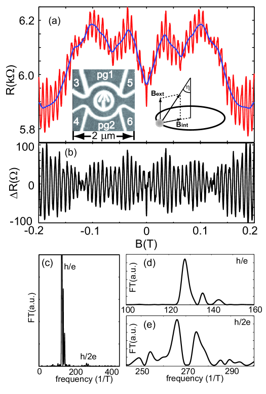
Fig. 1(a) shows the magnetoresistance of the ring (fast oscillating curve, red online). The low-frequency background resistance is indicated by a smooth curve (blue online). The observed Aharonov-Bohm (AB) oscillations with a period of 7.7 mT (frequency 130 T-1) correspond to a radius of the holes’ orbit of 415 nm, in excellent agreement with the lithographic size of the ring. The peak-to-peak amplitude of on a background of about 6 k corresponds to a visibility larger than . We restrict the measurements of the AB oscillations to magnetic fields in the range from -0.2 T to 0.2 T in order to prevent their mixing with SdH oscillations, which start to develop above 0.2 T. Throughout all measurements quantum point contact gates 3,4,5 and 6 are kept at the same values. Plunger gates pg1 and pg2 are set to V mV and V mV in the measurements presented in Fig. 1(a).
After subtracting the low-frequency background from the raw data, a clear beating pattern is revealed in the AB oscillations with a well defined node at mT [Fig. 1(b)], where a phase jump of occurs [arrow in Fig. 2(c)]. The position of the beating node indicates the presence of two oscillation frequencies differing by T-1.
The Fourier spectrum of the AB oscillations, taken in the symmetric magnetic field range (-0.2 T, 0.2 T), reveals an peak around 130 T-1 [Fig. 1(c)]. Zooming in on the peak, a splitting into 3 peaks at the frequencies 127 T-1, 136 T-1 and 143 T-1 is seen. We have carefully checked that this splitting is genuine to the experimental data and not a result of the finite data range, by reproducing it with different window functions for the Fourier transform. The differences of the oscillation frequencies agree with that anticipated from the position of the beating node in the raw data.
In contrast to the -periodic AB oscillations, which are very sensitive to phase changes in the ring arms, Altshuler-Aronov-Spivak (AAS) oscillations, originating from the interference of time reversed paths, are expected to be more robust if the microscopic configuration of the arms is changed. Besides, oscillations are less susceptible to the details how the spin rotates when it enters the ring than oscillations. This is due to the fact that the geometric phase accumulated along the paths contributing to the oscillations is larger than that in the case of the oscillations and cannot be completely cancelled by the spin rotations in the contacts, as in the latter case Yang04 . In Fig. 1(c) we can identify the peak at about 270 T-1 in the Fourier spectrum, corresponding to oscillations. If we zoom in on it [Fig. 1(e)], we see a splitting with the two main peaks having a separation of about 8 T-1, similar to the peak splitting. The splitting of the Fourier peak arises due to the frequency shift of the main peak by Engel00 , and the obtained splitting of 8 T-1 allows to estimate the SO induced intrinsic field to be T.
We now focus directly on the magnetic field-dependent resistance. In Fig. 2(a) we present the raw data after subtracting the low-frequency background (full line, red online) together with the filtered oscillations (dashed line) Sigrist04 . The contribution to the signal is the inverse Fourier transform of the peak in the Fourier spectrum. We will use the following notation below: denotes the raw data, is the low-frequency background, is the inverse Fourier transform of the peak and is the inverse Fourier transform of the peak in the Fourier spectrum. One can see in Fig. 2(a) that contains additional resistance modulations, beyond the oscillations. In order to demonstrate that those additional features are due to oscillations we plot in Fig. 2(b) the difference (full line, red online) and the curve obtained by inverse Fourier transform of the peak (dashed line) and find excellent agreement.
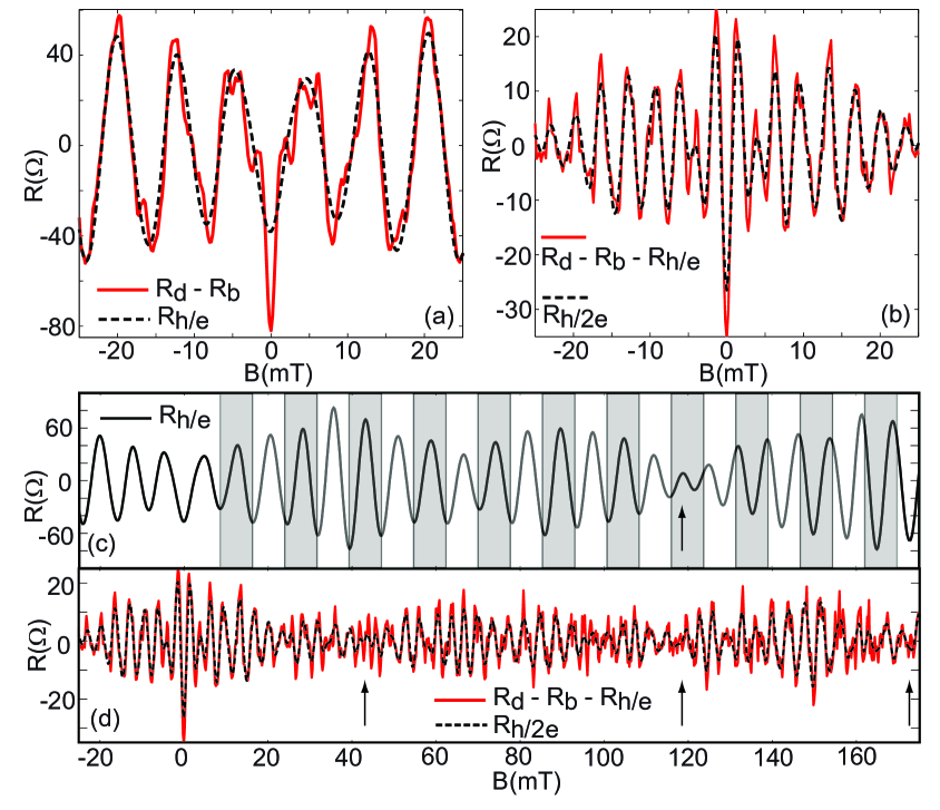
We further plot in Fig. 2(d) the difference (full line, red online), together with the filtered oscillations (dashed line) in a larger range of magnetic fields. A beating-like behavior in the oscillations is observed. Possible nodes develop around 40 mT, 115 mT, and 175 mT [arrows in Fig. 2(d)]. The appearance of these unequally spaced nodes is in agreement with the complex split-peak pattern in Fig. 1(e). In the plot of the filtered oscillations [Fig. 2(c)] we notice that only the node around 115 mT is common for both, and oscillations, while the other two nodes in the oscillations correspond to maxima in the beating of oscillations. This kind of aperiodic modulation of the envelope function of the oscillations, rather than a regular beating, is predicted for the case of diffusive rings in the presence of Berry’s phase Engel00 , since the latter also changes with increasing external magnetic field.
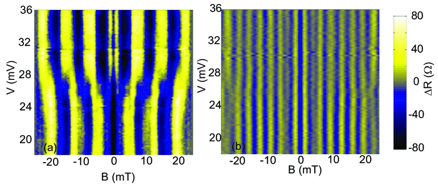
The evolution of the AB oscillations upon changing plunger gate voltages and is explored in Fig. 3(a). Plunger gate voltages are changed antisymmetrically: mV ; mV . Two distinct features are visible: there is always a local minimum in the AB oscillations at T, and the oscillations experience a phase jump by around mV. In order to understand the origin of these two features we analyze the filtered (not shown) and oscillations [Fig. 3(b)] as a function of . The oscillations experience a phase jump of , while the oscillations do not [Fig. 3(b)]. We have explored this behavior in several other gate configurations and always found the same result. The reason for such a behavior is that the oscillations are sensitive to the phase difference between the two arms, which can be changed by the plunger gates, while the AAS oscillations are not. We observe a resistance minimum at T for all gate configurations [Fig. 3(a)], which is due to a minimum at T in the oscillations [Fig. 3(b)]. It indicates that time reversed paths of the holes’ spinors interfere destructively due to strong SOI, in contrast to n-type GaAs systems where oscillations produce a resistance maximum at T Ihn03 . This effect has the same origin as the weak anti-localization (WAL) effect. However, the observed minimum is not caused by WAL in the ring leads, since the WAL dip in bulk 2D samples has a much smaller magnitude (less than , GrbicThesis07 ) than the minimum at T in the ring. The resistance minimum at T is a result of the destructive interference of the holes’ spins in the ring.
The adiabatic regime is reached when , where is the spin precession frequency around , while is the orbital frequency of the holes around the ring in the ballistic regime. p-type GaAs systems have strong SOI, and therefore large , which, together with a small (due to the large effective mass of the holes) makes p-types systems very favorable for reaching the adiabatic regime compared to other systems. Using the estimated value for of 0.25T and assuming a holes’ factor of 2, we obtain for the measured range of up to 0.2T. Therefore the adiabatic regime is not fully reached in our measurements.
There remains a pronounced discrepancy between the internal magnetic field obtained from the beating of the SdH oscillations of 7T (converting the corresponding energy scale meV to a magnetic field via the Zeeman splitting) and the field scale of 0.25 T obtained from the beating of the AB oscillations. The latter evaluation is strictly valid in the diffusive regime Engel00 while our sample is at the crossover to the ballistic regime. It is also not clear how the limited adiabaticity in our samples will influence these numbers.
In a straightforward picture one would expect that the node of the beating in the oscillations occurs at half the magnetic field as the node in the oscillations since the accumulated phase difference between the two spin species should be proportional to the path length travelled in the ring. Within experimental accuracy the data in Fig. 1 (d) and (e) suggests that the splitting in the corresponding Fourier transforms is the same.
In conclusion, we have measured Aharonov-Bohm oscillations in a ring defined on a 2D hole gas with strong spin-orbit interactions. We observe a beating in the measured resistance which arises from an interplay between the orbital Aharonov-Bohm and a spin-orbit induced geometric phase. In addition we resolve oscillations in the ring resistance, and find that they also show a beating-like behavior, which produces a splitting of the peak in the Fourier spectrum. A resistance minimum at , present in all in-plane gate configurations, demonstrates the destructive interference of the hole spins propagating along time reversed paths.
We thank Daniel Loss and Yigal Meir for stimulating discussions. Financial support from the Swiss National Science Foundation is gratefully acknowledged.
References
- (1) Y. Aharonov and D. Bohm, Phys. Rev. 115, 485 (1959)
- (2) M.V. Berry, Proc. R. Soc. A 392, 45 (1984)
- (3) Y. Aharonov and J. Anandan, Phys. Rev. Lett. 58, 1593 (1987)
- (4) D. Loss, H. Schoeller, P.M. Goldbart Phys. Rev. B 59, 13328 (1999).
- (5) H.A. Engel and D. Loss, Phys. Rev. B 62, 10238 (2000)
- (6) Y. Meir, Y. Gefen and O. Entin-Wohlman, Phys. Rev. Lett. 63, 798 (1989); A.G. Aronov and Y.B Lyanda-Geller, Phys. Rev. Lett. 70, 343 (1993); H. Mathur and A.D. Stone, Phys. Rev. Lett. 68, 2964 (1992); T. Z. Qian and Z.B. Su, Phys. Rev. Lett. 72, 2311 (1994); J. Nitta, F.E. Meijer, H. Takayanagi, Appl. Phys. Lett. 75, 695 (1999); D. Frustaglia and K. Richter, Phys. Rev. B 69, 235310 (2004).
- (7) A. F. Morpurgo, J. P. Heida, T. M. Klapwijk, B. J. van Wees, and G. Borghs, Phys. Rev. Lett. 80, 1050 (1998).
- (8) J.B. Yau, E.P. De Poortere and M. Shayegan, Phys. Rev. Lett. 88, 146801 (2002).
- (9) M.J. Yang, C.H. Yang, Y.B. Lyanda-Geller, Europhys. Lett. 66, 826 (2004).
- (10) M. König et al., Phys. Rev. Lett. 96, 076804 (2006)
- (11) T. Bergsten, T. Kobayashi, Y. Sekine, and J. Nitta, Phys. Rev. Lett. 97, 196803 (2006)
- (12) B. Habib, E. Tutuc, and M. Shayegan, Appl. Phys. Lett. 90, 152104 (2007).
- (13) R. Winkler, Spin-Orbit Coupling Effects in Two-Dimensional Electron and Hole Systems, Springer Tracts in Modern Physics, Volume 191, Springer-Verlag (2003)
- (14) A. Stern, Phys. Rev. Lett. 68, 1022 (1992)
- (15) A. G. Mal’shukov, V. V. Shlyapin, and K. A. Chao, Phys. Rev. B 60, R2161 (1999)
- (16) H. De Raedt, Phys. Rev. Lett. 83, 1700 (1999); A. F. Morpurgo, J. P. Heida, T. M. Klapwijk, B. J. van Wees, and G. Borghs, Phys. Rev. Lett. 83, 1701 (1999)
- (17) A. G. Mal’shukov and K. A. Chao, Phys. Rev. Lett. 90, 179701 (2003); J. B. Yau, E. P. De Poortere, and M. Shayegan, Phys. Rev. Lett. 90, 179702 (2003); A. G. Wagh and V. C. Rakhecha, Phys. Rev. Lett. 90, 119703 (2003); J. B. Yau, E. P. De Poortere, and M. Shayegan, Phys. Rev. Lett. 90, 119704 (2003)
- (18) B. Grbić, R. Leturcq, K. Ensslin, D. Reuter, and A.D. Wieck Appl. Phys. Lett. 87, 232108 (2005)
- (19) Boris Grbić, PhD thesis No. 17248, ETH Zurich (2007).
- (20) J. P. Lu et al., Phys. Rev. Lett. 81, 1282 (1998)
- (21) M. Sigrist et al., Phys. Rev. Lett. 93, 066802 (2004).
- (22) T. Ihn et al., Advances in Solid State Physics Vol. 43 eddited by B. Kramer (Springer-Verlag, New York, 2003) p. 139; A. E. Hansen, A. Kristensen, S. Pedersen, C. B. Sørensen, and P. E. Lindelof, Phys. Rev. B 64, 045327 (2001).