Magnetic structure of Sm2IrIn8
Abstract
The magnetic structure of the intermetallic antiferromagnet Sm2IrIn8 was determined using x-ray resonant magnetic scattering (XRMS). Below = 14.2, Sm2IrIn8 has a commensurate antiferromagnetic structure with a propagation vector . The Sm magnetic moments lie in the ab plane and are rotated roughly 18º away from the a axis. The magnetic structure of this compound was obtained by measuring the strong dipolar resonant peak whose enhancement was of over two orders of magnitude at the edge. At the edge both quadrupolar and dipolar features were observed in the energy line shape. The magnetic structure and properties of Sm2IrIn8 are found to be consistent with the general trend already seen for the Nd-, Tb- and the Ce-based compounds from the RmMnIn3m+2n family (R = rare earth; M=Rh or Ir, = 1, 2; n = 0, 1), where the crystalline electrical field (CEF) effects determine the direction of magnetic moments and the evolution in the series. The measured Néel temperature for Sm2IrIn8 is slightly suppressed when compared to the of the parent cubic compound SmIn3.
pacs:
75.25.+z, 75.50.Ee, 75.30.-m, 75.30.KzI INTRODUCTION
The microscopic details of -electron magnetism play a fundamental role in the physical properties of various classes of rare-earth based materials such as heavy fermions, magnetically ordered alloys and permanent magnets. The existence of structurally related families of rare-earth based compounds provides a great opportunity to explore how the details of the -electrons magnetism evolve as a function of changes in the dimensionality, local symmetry and electronic structure along each related family. The recently discoveredHegger et al. (2000); Petrovic et al. (2001a, b); Thompson et al. (2001); Pagliuso et al. (2001a); Pagliuso et al. (2000); Lora-Serrano et al. (2006a); Chen et al. (2002) family of intermetallic compounds RmMnIn3m+2n (M = Co, Rh or Ir, = 1, 2; = La, Ce, Pr, Nd, Sm, Gd) have proved to be very promising in this regard, since it possesses many members of structurally related heavy-fermions superconductors (HFS), for R = Ce, antiferromagnets (R = Nd, Sm, Gd and Tb) and paramagnetic metals (R = La, Pr). Within this family, the physical properties of a particular R-member can also be compared to compounds based on the same R with three different related structures [the cubic RIn3 and the tetragonal RMIn5(1-1-5) and R2MIn8 (2-1-8)]Moshopoulou et al. (2001, 2006); Buschow et al. (1969) and/or to the same R formed with three distinct transition metals (M = Rh, Ir and Co - not for all R -) in the same structure.
For the Ce-based HFS in this family, extensive investigation has revealed fascinating physical properties such as quantum criticality, non-fermi-liquid-behavior and an intriguing interplay between magnetism and superconductivity, reflected in very rich phase diagrams.Pagliuso et al. (2001b); Pagliuso et al. (2002); Pham et al. (2006); Zapf et al. (2002); Park et al. (2006); Sidorov et al. (2002); Bianchi et al. (2003); Bauer et al. (2005); Paglione et al. (2003) Because the HFS members of this family are structurally related, its investigation has been used to provide some insights on the question why some structure types are favorable to host many superconductors. A possible relationship between the superconducting critical temperature Tc and the crystalline anisotropyPagliuso et al. (2002); Kumar and A. L. Cornelius (2004); Oeschler et al. (2003), the role of the -electron hybridization with the conduction electrons in the occurrence of superconductivityChristianson et al. (2004); Harrison et al. (2004); Raj et al. (2005) and the effects of quasi-2D electronics structuresHall et al. (2001a, b); Costa-Quintana and López-Aguilar (2003)are some of the physical phenomena that have been brought to the scenario to answer the question above. Further, motivated by this experimental trend, new materials search based on the 1-1-5 structures has led to the discovery of the Pu-based HFS PuMGa5 (M = Rh and Co).Sarrao et al. (2002); Bauer et al. (2004)
On the other hand, as these HFS are presumably magnetically mediated, others studiesKumar and A. L. Cornelius (2004); Christianson et al. (2005); Pagliuso et al. (2001a); Pagliuso et al. (2000); Lora-Serrano et al. (2006b, a); Hieu et al. (2006); Malinowski et al. (2003); Correa et al. (2004); Granado et al. (2004); Pagliuso et al. (2006) have been focused in understanding the evolution of the local magnetism, not only for the magnetically ordered Ce-based members of this family such as CeRhIn5 and Ce2RhIn8, but also for their antiferromagnetic counterparts RmMnIn3m+2n (M = Rh or Ir, = 1, 2;) for = Nd, Sm, Gd and Tb. From these studies, it was established the role of tetragonal crystalline electrical field (CEF) in determining the spatial direction of the ordered R-moments with respect to the lattice and the evolution of the Néel temperature, , in the series.Pagliuso et al. (2001a); Pagliuso et al. (2000); Lora-Serrano et al. (2006b, a); Pagliuso et al. (2006)
A key set of experiments allowing the above conclusions was the experimental determination of the magnetic structures of various members of the RmMnIn3m+2n (M = Rh or Ir, = 1, 2;) family.wei ; Bao et al. (2001); Chang et al. (2002); Christianson et al. (2005); Lora-Serrano et al. (2006a); Granado et al. (2004, 2006) Up to date, however, none of the Sm-based compounds from this family have had their magnetic structures determined. In fact, the compounds of this series containing Sm ions may be particularly important in testing the extension of the CEF trends in this family because the presence of excited -multiplet states in Sm3+ and quadrupolar interactions have to be taken into account in order to understand their magnetic phase diagrams.Kasaya et al. (1985); Endoh et al. (1989); Kletowski (1998); Stunault et al. (2002) Especially interesting is Sm2IrIn8 which presents a first order antiferromagnetic transition at = 14.2 K.Pagliuso et al. (2001a) This value is slightly smaller than the 16 K of the cubic SmIn3Buschow et al. (1969) which according to the CEF trends observed in other members of this familyLora-Serrano et al. (2006a); Pagliuso et al. (2006) suggest that the ordered Sm-moments should lie the -plane.
To further explore the magnetic properties of Sm2IrIn8 and to check the extension of the CEF trends observed for R = Nd, Tb, and Ce,Pagliuso et al. (2001a); Pagliuso et al. (2000); Lora-Serrano et al. (2006b, a); Pagliuso et al. (2006) to the Sm-based compounds, we report in this work the solution of the magnetic structure of the intermetallic antiferromagnet Sm2IrIn8 by means of the x-ray resonant magnetic scattering (XRMS) technique. The XRMS technique has proved to be a very important tool for the investigation of microscopic magnetism in condensed matter, specially for highly neutrons absorber ions such as Sm.
Sm2IrIn8 presents, below = 14.2 K, a commensurate antiferromagnetic structure with a propagation vector . The Sm magnetic moments lie in the ab plane. In terms of relative orientation, the propagation vector indicates that the Sm-spins are ordered antiferromagnetically along the a axis and ferromagnetically along the b axis and, because of the presence of two Sm ions per unit cell along c axis, some calculations have to be performed in order to determine the type of ordering along this direction. Furthermore, as it could be expected for such spin arrangement in a tetragonal compound, antiferromagnetic domains were observed in the ordered state of Sm2IrIn8. These domains were removed by field-cooling the sample at a field of = 10 T.
II EXPERIMENT
Single crystalline samples of Sm2IrIn8 were grown from Indium flux as described previously.Fisk and Remeika (1989); Pagliuso et al. (2001a) The crystal structure, unit cell dimensions and macroscopic properties of the Sm2IrIn8 single crystals used in this work were in agreement with the data in Ref. Pagliuso et al., 2001a. For the XMRS experiments of this work, selected crystals were extracted and prepared with polished (0,0,) flat surfaces, and sizes of approximately 4 mm x 3.4 mm x 1.5 mm. The preferred crystal growth direction of this tetragonal compound is columnar along the [00l] direction and the (001) facet is relatively large. The mosaic spread of the sample was found to be ° by a rocking curve ( scan) on a Phillips four circle diffractometer.
XRMS studies were performed at the 4-ID-D beamline at the Advanced Photon Source (APS) and at the ID-20 beamline at the European Synchrotron Radiation Facility (ESRF). The 4-ID-D x-ray source is a 33 mm period planar undulator and the energy is selected with a double crystal Si(111) monochromator. A toroidal mirror focuses the beam to a 220 m (horizontal) x 110 m (vertical) spot, yielding an incident flux of 3.5 x 10¹³ photons/s with an energy resolution of = 1.4 x 10⁻⁴. The sample was cooled in a closed-cycle He refrigerator (with a base temperature of 4 K) with a dome Be window. Our experiments were performed in the coplanar geometry with -polarized incident photons, i.e., in the vertical scattering plane, using a four-circle diffractometer. Except for azimuthal scans, the sample was mounted with the b axis perpendicular to the scattering plane.
In most measurements, we have performed a polarization analysis, whith Cu(220), Graphite (006) and Au(111) crystal analysers, appropriate for the energies of Sm and edges. The diffractometer configuration at the APS allowed measurements at different azimuthal angles () by rotating the sample around the scattering vector Q. This was particularly useful to probe the magnetic moment components at the dipolar resonant condition with incident polarization.
The x-ray source on the ID-20 beamline was a linear undulator with a 32 mm period. The main optical components are a double Si(111) crystal monochromator with sagital focusing and two meridional focusing mirrors on either side of the monochromator. At 7.13 keV using the first harmonic of the undulator u32, the standard incident flux at the sample position was approximately 1 x 10¹³ ph/s at 200 mA with a beam size of 500 m (horizontal) x 400 m (vertical). The sample was mounted on a cryomagnet (with a base temperature of 2 K), installed on a horizontal six-circle diffractometer, with the b axis parallel to the cryomagnet axis and perpendicular to the scattering plane. This configuration allowed -polarized incident photons in the sample and the application of an external magnetic field up to 10 T perpendicular to the scattering plane.
III RESULTS
III.1 Temperature dependence and resonance analysis
Magnetic peaks were observed in the dipolar resonant condition at temperatures below = 14.2 K at reciprocal lattice points forbidden for charge scattering and consistent with an antiferromagnetic structure with propagation vector . Their temperature dependence was studied for increasing and decreasing temperature sweeps. Figure 1 shows the temperature dependence of () magnetic reflection at an incident photon energy of 7.313 keV ( edge) and measured at incident polarization without polarization analysis. The squared root of the integrated intensity, which is proportional to a Sm sub-lattice magnetization, is displayed. A pseudo-voigt peak shape was used to fit transversal scans through the reciprocal lattice points in order to obtain the integrated intensities of the reflection peak. This peak intensity decreases abruptly to zero for T 13 K and its critical behavior can not be described by a power-law function with a critical exponent . This result is in agrement with the first order character of the magnetic transition at 14.2 K, revealed by heat capacity data, from which a latent heat of J/mol was extracted.Pagliuso et al. (2001a) Consistently, we found evidence of small hysteresis for T 14.2 when changing from warming to the cooling temperature sweep.

The energy line shape curves for the polarization channels - ’ and - ’ of the (,0,9) diffraction peak at (a) the and (b) the absorption edges of Sm3+ ion at = 5.9 K are shown in Figure 2. The solid lines in both panels represent the absorption spectrum, , extracted from fluorescence yield. The data of Figure 2 were collected at the 4-ID-D beamline of APS by counting the photons reaching the detector at a fixed Q while changing the incident energy. The strong resonant enhancement of the x-ray scattering at this reciprocal space position provide clear evidence of the magnetic origin of the observed peaks.
The energy scan curve in Figure 2(a) has a maximum at 7.312 keV which is only 2.5 eV larger than the absorption edge (defined by the inflection point of the absorption spectrum), revealing the electric dipolar character (E1) of this transition (from 2p to 5d states). Figure 2 also shows the polarization analysis performed to unambiguously confirm the magnetic origin of the superstructure peaks. Polarization analysis was also used to verify whether the anomaly at approximately 8 eV below the dipolar peak in Figure 2(a) could be associated with a quadrupolar transitionHill and McMorrow (1996) or it simply represents an enhanced interference between the non-resonant and the resonant part of the scattering amplitude. For the experimental configuration used (incident -polarization), the electric dipole transitions E1 rotate the plane of polarization into the scattering plane (-polarization). Our data in Figure 2(a) reveals a strong enhancement of the scattered intensities at the - ’ channel (closed circles) and no enhancement at the ’ channel for the same energy range. These results confirm the magnetic origin of the ) reflections due to the existence of an antiferromagnetic structure doubled along the crystallographic direction, with a propagation vector .
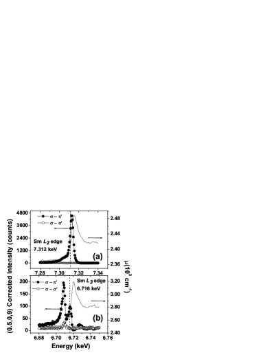
The energy profile around the Sm edge is presented in Figure 2(b). Firstly, the observed intensities are roughly one order of magnitude weaker than those obtained at the resonance, in agreement with previous measurements on pure Sm.Stunault et al. (2002) Secondly, there are two peaks in the - ’ channel signal, as also observed for other light rare-earthZheludev et al. (1996); Hill et al. (1995) and Sm-based compounds.Stunault et al. (2002); Detlefs et al. (1997) A high energy peak appears at 6.716 keV, while a low energy and more intense enhancement can be observed at 6.708 keV. Interestingly, Stunault et al.Stunault et al. (2002) have demonstrated that for pure Sm the quadrupolar E2 resonance is more intense than the dipolar E1 at the edge and they found that the energy difference between the E2 and the E1 resonances is of the order of 8 eV, the same as the one found in this work. Furthermore, in the - ’ channel only an enhancement at 6.708 keV could be observed which is consistent with the quadrupolar character of this resonance, since scattering signal in - ’ channel for dipolar transitions is strictly forbidden.Hannon et al. (1988); Hill and McMorrow (1996) Thus, the presence of this pre-edge enhancement in the energy curves of Figure 2 confirms an expected quadrupole (E2) 2p to 4f contribution to the resonant x-ray scattering in Sm2IrIn8.
III.2 The magnetic structure
The magnetic structure of the Sm2IrIn8 was experimentally investigated using dipolar resonant x-ray magnetic scattering with polarization analisys. In general, the magnetic scattering intensities are given by:Detlefs et al. (1997); Hill and McMorrow (1996)
| (1) |
where is the absorption correction for asymmetric reflections, 2 is the scattering angle, is the wave-vector transfer, and ( and ) are the incident and scattered wave (polarization) vectors, respectively. is the position of the nth resonant atom in the lattice, and is the moment direction of this atom. The resonant scattering amplitude contains both dipole (E1) and quadrupole (E2) contributions. For the determination of the magnetic structure of this work we have used the second term of the electric dipole transition (E1) form factor which produces magnetic peaks. In this case we have:
| (6) |
where is the Bragg angle, , and are the components of the magnetic moment at the nth site, according to the commonly used geometry convention of Ref. Blume and Gibbs, 1988; , , ’ and ’ describe the incident (non-primed terms) and scattered (primed) photon polarizations.
As described previously, two experimental setups have been used in this work, in the vertical (4-ID-D beamline) and horizontal (ID-20) scattering configurations. This permitted us to access all four polarization channels of the 2x2 matrix in (6) and to determine the magnetic moment orientations through their polarization dependence at the E1 resonance by comparing the relative intensities of experimental magnetic peaks with the calculated ones using the appropriate terms of matrix (6).Detlefs et al. (1997)
| MODEL I | MODEL II | ||||
| () | Exp. Data | m//c | m//a | m//c | m//a |
|---|---|---|---|---|---|
| (1/2,0,6) | 66 | 13 | 29 | 24 | 55 |
| (1/2,0,7) | 78 | 17 | 29 | 39 | 68 |
| (1/2,0,8) | 5 | 77 | 100 | 3.4 | 4.5 |
| (1/2,0,9) | 100 | 3 | 3 | 100 | 100 |
| (1/2,0,10) | 12 | 100 | 68 | 32 | 23 |

In the case of Sm2IrIn8 the magnetic propagation vector does not unequivocally determine the magnetic structure due to the presence of two magnetic Sm atoms per chemical unit cell along the direction. Therefore, as stated above, we have an antiparallel ordering of the Sm moments along the direction and a parallel ordering along . Along there are, however, two possibilities of coupling that can take place: a parallel arrangement (Model I), in which the moments of neighboring Sm ions along c axis are parallel to each other (sequence ), or the antiparallel coupling (Model II), with the sequence (). These two possibilities have been considered into the calculated magnetic structure factor while orienting the magnetic moment along the three crystallographic directions for five different magnetic Bragg peaks, with l = 6, 7, 8, 9, 10. The calculated intensities are strongly dependent on the projections of magnetic moments along the crystallographic axis through the product of equation (6). Therefore, they were compared to the relative observed intensities for each case. This evaluation was performed at the vertical geometry of the 4-ID-D beamline at 9 K by performing rocking scans with the crystal analyzer and numerically integrating the data.Detlefs et al. (1997) We show this analysis in Table 1, where “Model I” stands for the sequence and “Model II” for the one. This comparison shows that the model which best fits the experimental data is the one assuming antiparallel coupling along c axis (Model II) with the magnetic moments approximately oriented along the a axis (according to matrix (6), for a polarized incident beam and peaks at reciprocal space positions with the (001) normal surface contained in the scattering plane, contributions from an oriented moment along direction cannot be detected).
In addition, we have also measured the and polarization channels at the horizontal geometry of the ID-20 beamline. Measuring these two channels we gained access to the and components (in equation 2) of magnetic moment vector in one case [, Figure 3(a)] and to in the other [, Figure 3(b)]. There is a clear indication that for the channel the observed data are well fit when considering the moments along the direction [dotted curve in Figure 3(a)] instead of direction [short dashed curve]. Also in this case the E1 terms are not sensitive to the component of the ordered moment perpendicular to the scattering plane, i.e. along b axis. Further, when measuring the channel () we are only allowed to measure the b component, which is confirmed by the good fit of experimental data when assuming magnetic moments along such direction [dash-dotted curve in Figure 3(b)]. These two last results indicate that the Sm moments actually have components along both a and b real space axis and not perfectly aligned along any of these two directions.

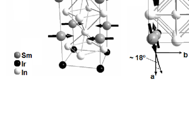
To determine the exact orientation of the magnetic moments within the ab plane, we have performed azimuthal scans ( scan) through the () reflection (Figure 4) at the E1 resonance. At the polarization channel this procedure warrants the determination of moments directions with no ambiguity because the magnetic cross section is strongly dependent of the magnetic moment direction and the polarization of the incoming and scattered radiation, the maximum (minimum) intensity in the curve will occur with the magnetic moment being parallel (perpendicular) to the diffraction plane. With the experimental setup of 4-ID-D beamline we had access to record points at azimuthal angles between -50º and 60º. In order to compare with the observed data, one can calculate the intensities for the channel using the expressions (1) and (6) and a reasonably simple geometry analysis considering the projections of both and on the coordinate system of Ref. Blume and Gibbs, 1988 when the azimuth angle is changed. Then, the calculated intensity is proportional to -cos cos cos + sin sin, where represents the assymetry angle between the scattering and the normal surface vector.Detlefs et al. (1997) Figure 4 shows the experimental and the calculated relative intensities considering the moment along the a and b axis, as well as 18º tilted from the a axis, which is the value that nicely adjust the experimental data. Considering the experimental errors we can then conclude that the magnetic moment is in the ab plane making (18º 3º) with the direction of the sample. Using all the above results, a model of the magnetic unit cell of Sm2IrIn8 can be constructed and is shown in Figure 5.
As it was observed in the magnetic structure of other members of the RmMIn3m+2 series such as NdRhIn5wei , TbRhIn5,Lora-Serrano et al. (2006a) GdRhIn5,Granado et al. (2006) and Gd2IrIn8Granado et al. (2004) the magnetic structure of Sm2IrIn8 presents a lower symmetry than the crystallographic structure, as the Sm spins present different relative orientations along the and directions even though and are indistinguishable. This spin arrangement was explained by considering the first () and second () R-neighbors exchange interactions in the case of a small / ratio.Granado et al. (2006)
Considering the observation of this kind of magnetic structure in tetragonal compounds, it may be expected that at zero magnetic field the antiferromagnetic ordering takes place with the formation of antiferromagnetic domains where the relative orientation of the magnetic moments along a given direction ( or ) changes from parallel to antiparallel between the domains. The presence of a twinned magnetic structure with symmetry-related domains was evidenced by the observation of both () and () reflection-types in this work. To further investigate the presence of antiferromagnetic domains in the ordering state of Sm2IrIn8 we follow the behavior of the magnetic () and () reflections under an applied magnetic field.

Figure 6 presents the behavior of the () and () intensities as a function of the applied magnetic field of 10 T along one of the tetragonal axis in the plane (defined as direction). At zero field and = 6 K, both () [open circles] and () [closed squares] intensities can be observed with comparable magnitude [Figure 6(a)]. The () intensity is roughly 66% that of the () peak. The sample was then field cooled ( = 10 T) from the paramagnetic (16 K) to the ordered state (6 K) with the field applied along the direction. As can be seen in Figure 6(b) the () diffraction peak disappears as the magnetic field favors the parallel spin orientation along the axis. The same effect was also observed for the other five () reflections (not shown). The results under applied magnetic field shown in Figure 6 confirm the existence of a twinned magnetic structure for Sm2IrIn8 which allows the observation of both () and () magnetic reflections at zero field.
IV DISCUSSION
Early studies on the antiferromagnetic cubic compound SmIn3 have shown multiple magnetic transitions associated with quadrupolar ordering, magnetoelastic and magnetocrystalline competitive effects at 14.7, 15.2 and 15.9 K (the former two temperatures being associated with successive magnetic dipolar, antiferromagnetic, orders and the last one due to quadrupolar ordering).Kasaya et al. (1985); Endoh et al. (1989) For the tetragonal Sm2IrIn8, the insertion of two additional SmIn3 atomic layers into the crystalline structure slightly decreases compared to that of SmIn3 (14.2 and 15.2 K for the Sm2-1-8 and Sm1-0-3 ’s, respectively) and an additional anomaly at 11.5 K has been observed in the specific heat and resistivity measurements,Pagliuso et al. (2001a) probably related to the successive transitions seen in the ordered phase of the SmIn3.
Following the investigation of the isostructural magnetic non-Kondo compounds from the RmMIn3m+2 family, where the details the 4 magnetism along the series may be important to understand the possible magnetic-mediated superconductivity in the compounds with R = Ce, we have studied the magnetic structure of Sm2IrIn8, which is the only compound from this family with a clear first order antiferromagnetic transition and now it is the first Sm-member from this family with a solved magnetic structure, which is the main result of this work. The determination of the Sm2-1-8 magnetic structure allows for the investigation of the CEF driven trends of magnetic properties within the RmMIn3m+2 family to be extended to the Sm-based members.
Our results confirm the complex resonance profile of Sm-based compounds (at one satellite reciprocal point, Figure 2), as seen in previous studies of pure Sm.Stunault et al. (2002) It has been argued that the larger intensity of E2 resonance at Sm edge compared to its intensity at the edge may be explained qualitatively by the spin-orbit splitting of the intermediate 4f levels involved.Stunault et al. (2002) The transitions connect the state while involves transitions to the level, which lie lower in energy and therefore can be preferentially populated by the five 4f Sm electrons. This reduces the number of vacant states from 6 to 1, in contrast to the 8 states available for the level, which increases the transition probability of the E2 resonance at Sm in Sm2IrIn8.
Considering the additional magnetic transitions observed for SmIn3,Kasaya et al. (1985); Endoh et al. (1989) and the additional anomaly at = 11.5 K in heat capacity and electrical resistivity measurements for Sm2IrIn8,Pagliuso et al. (2006) we did not observe any discontinuities, within the resolution of our experiment, in the integrated intensities of the () magnetic peak from roughly 4 K up to 16 K (Figure 1). Therefore we conclude that there are no changes of the magnetic propagation vector below . For completeness, on going field-dependent heat capacity and thermal expansion measurements (not shown and will be published elsewhere) have revealed no field-induced transitions up to H=9 and 18 T, respectively, similarly to SmIn3 where no additional transition was found with applied field up to H=32 T.Kletowski (1998)
On the other hand, recent works have shown that the low temperature CEF configuration plays a fundamental role on the behavior of and the magnetic moment directions within the RmMIn3m+2 family.Chang et al. (2002); Pagliuso et al. (2006); Lora-Serrano et al. (2006b, a) Further, Kubo et al.Kubo and Hotta (2006) has also proposed an orbital controlled mechanism for superconductivity in the Ce-based compounds from this family. For the Sm members, CEF effects confine the magnetic moments to the ab plane, consistent with the experimental CEF trends observed for R = Ce, Nd and TbPagliuso et al. (2001a); Pagliuso et al. (2000); Lora-Serrano et al. (2006b, a) and also by the predictions of a recently developed mean field theoretical model.Pagliuso et al. (2006); Lora-Serrano et al. (2006a) If the magnetic ordered moments lie in the -plane but they are more magnetically susceptible along the axis the magnetic order can be frustrated to lower values than for their cubic relatives. The mean-field model of Ref. Pagliuso et al., 2006, however, only includes the contributions of tetragonal CEF and first neighbor isotropic dipolar exchange interaction. Therefore, it may not be expected to work for Sm containing compounds, because for the Sm3+ ion the first excited J-multiplet lying just above the ground state is closer in energy. Thus, the tetragonal CEF splitting can mix both the excited and ground state CEF scheme and this particular effect should be considered into the calculations. Indeed, this is the responsible for the non-linear response of the inverse of magnetic susceptibility at high temperatures on SmIn3 and other Sm-based compounds,Buschow et al. (1969); Tsuchida and Wallace (1965) as well as in Sm2IrIn8.Pagliuso et al. (2001a) Furthermore, as it was found for SmIn3,Kasaya et al. (1985); Endoh et al. (1989) quadrupolar magnetic interactions also have to be considered in order to achieve a complete description of the magnetic properties of the Sm-based compounds in the RmMIn3m+2 family.
Apart from the higher complexity of the magnetic properties of the Sm-compounds, it was found experimentally that is decreased (roughly ) for the tetragonal compounds when compared to the cubic SmIn3. In addition, we have found that the magnetic structure of Sm2IrIn8 shows the ordered Sm moments in the plane, as expected in the case of suppression.Pagliuso et al. (2006); Lora-Serrano et al. (2006a) Although the changes in for the Sm compounds are much smaller (perhaps due to the particularities of the Sm3+ ion discussed above) than that observed for R = Ce, Nd and Tb in the RmMIn3m+2 family, we can conclude with the solution of the magnetic structure reported here, that the general CEF trend of the RmMIn3m+2 is also qualitatively present in Sm2IrIn8.
V CONCLUSION
In summary, we have presented the results of the magnetic structure determination of the intermetallic antiferromagnet Sm2IrIn8. The magnetic order is commensurate with propagation vector and the Sm moments oriented in the ab plane. We used different scattering geometries (exploring the polarization dependences of magnetic intensities) and azimuthal scans around a magnetic reciprocal space point to determine without ambiguity that the moments are aligned approximately 18º away from the a axis. The temperature behavior of the magnetic satellites have been probed at the () reciprocal node and show no evidence of changes in the magnetic structure within the studied temperature range. Besides, an abrupt (non-power law) decrease of magnetic intensities at was found, consistent with the first order character of the antiferromagnetic transition of Sm2IrIn8. The resonance properties at the Samarium and absorption edges revealed both resonant E1 and E2 process with roughly one order of magnitude more intense resonance peaks at the edge and a much stronger quadrupole resonance in the edge. The orientation of Sm moments in the ab plane and the small decrease of compared to its value for SmIn3 agrees with a general CEF trend found in the RmMIn3m+2 family.
Acknowledgements.
This work was supported by FAPESP (SP-Brazil) Grants No. 05/55272-9, 05/00962-0, 04/08798-2 and 03/09861-7, CNPq (Brazil) Grants No. 307668/03, 04/08798-2, 304466/20003-4 and 140613/2002-1, and FAEPEX (SP-Brazil) Grant No. 633/05. Use of the Advanced Photon Source was supported by the U. S. Department of Energy, Office of Science, Office of Basic Energy Sciences, under Contract No. DE-AC02-06CH11357. The staff at the 4-ID-D and ID-20 beam lines are gratefully acknowledged for providing an outstanding scientific environment during these experiments.References
- Hegger et al. (2000) H. Hegger, C. Petrovic, E. G. Moshopoulou, M. F. Hundley, J. L. Sarrao, Z. Fisk, and J. D. Thompson, Phys. Rev. Lett. 84, 4986 (2000).
- Petrovic et al. (2001a) C. Petrovic, R. Movshovich, M. Jaime, P. G. Pagliuso, M. F. Hundley, J. L. Sarrao, J. D. Thompson, and Z. Fisk, Europhys. Lett. 354-359, 4986 (2001a).
- Petrovic et al. (2001b) C. Petrovic, P. G. Pagliuso, M. F. Hundley, R. Movshovich, J. L. Sarrao, J. D. Thompson, Z. Fisk, and P. Monthoux, J. Phys.: Condens. Matter 13, L337 (2001b).
- Thompson et al. (2001) J. D. Thompson, R. Movshovich, Z. Fisk, F. Bouquet, N. J. Curro, R. A. Fisher, P. C. Hammel, H. Hegger, M. F. Hundley, M. Jaime, et al., J. Magn. Magn. Mat. 226-230, 5 (2001).
- Pagliuso et al. (2001a) P. G. Pagliuso, J. D. Thompson, M. F. Hundley, J. L. Sarrao, and Z. Fisk, Phys. Rev. B 63, 054426 (2001a).
- Pagliuso et al. (2000) P. G. Pagliuso, J. D. Thompson, M. F. Hundley, and J. L. Sarrao, Phys. Rev. B 62, 12266 (2000).
- Lora-Serrano et al. (2006a) R. Lora-Serrano, C. Giles, E. Granado, D. J. Garcia, E. Miranda, O. Agüero, L. M. Ferreira, J. G. S. Duque, and P. G. Pagliuso, Phys. Rev. B 74, 214404 (2006a).
- Chen et al. (2002) G. Chen, S. Ohara, M. Hedo, Y. Uwatoko, K. Saito, M. Sorai, and I. Sakamoto, J. Phys. Soc. Japan 71, 2836 (2002).
- Moshopoulou et al. (2001) E. G. Moshopoulou, Z. Fisk, J. L. Sarrao, and J. D. Thompson, J. Solid State Chem. 158, 25 (2001).
- Moshopoulou et al. (2006) E. G. Moshopoulou, R. M. Ibberson, J. L. Sarrao, J. D. Thompson, and Z. Fisk, Acta Crystallographica B 62, 173 (2006).
- Buschow et al. (1969) K. H. J. Buschow, H. W. de Wijn, and A. M. van Diepen, J. Chem. Phys. 50, 137 (1969).
- Pagliuso et al. (2001b) P. G. Pagliuso, C. Petrovic, R. Movshovich, D. Hall, M. F. Hundley, J. L. Sarrao, J. D. Thompson, and Z. Fisk, Phys. Rev. B 64, 100503(R) (2001b).
- Pagliuso et al. (2002) P. G. Pagliuso, R. Movshovich, A. D. Bianchi, M. Nicklas, J. D. Thompson, M. F. Hundley, J. L. Sarrao, and Z. Fisk, Physica B 312-313, 129 (2002).
- Pham et al. (2006) L. D. Pham, T. Park, S. Maquilon, J. D. Thompson, and Z. Fisk, Phys. Rev. Lett. 97, 056404 (2006).
- Zapf et al. (2002) V. S. Zapf, E. J. Freeman, E. D. Bauer, J. Petricka, C. Sirvent, N. A. Frederick, R. P. Dickey, and M. B. Maple, Phys. Rev. B 65, 014506 (2002).
- Park et al. (2006) T. Park, F. Ronning, H. Q. Yuan, M. B. Salamon, R. Movshovich, J. L. Sarrao, and J. D. Thompson, Nature 440, 65 (2006).
- Sidorov et al. (2002) V. A. Sidorov, M. Nicklas, P. G. Pagliuso, J. L. Sarrao, Y. Bang, A. V. Balatsky, and J. D. Thompson, Phys. Rev. Lett. 89, 157004 (2002).
- Bianchi et al. (2003) A. Bianchi, R. Movshovich, I. Vekhter, P. G. Pagliuso, and J. L. Sarrao, Phys. Rev. Lett. 91, 257001 (2003).
- Bauer et al. (2005) E. D. Bauer, C. Capan, F. Ronning, R. Movshovich, J. D. Thompson, and J. L. Sarrao, Phys. Rev. Lett. 94, 047001 (2005).
- Paglione et al. (2003) J. Paglione, M. A. Tanatar, D. G. Hawthorn, E. Boaknin, R. W. Hill, F. Ronning, M. Sutherland, L. Taillerfer, C. Petrovic, and P. C. Canfield, Phys. Rev. Lett. 91, 246405 (2003).
- Kumar and A. L. Cornelius (2004) R. S. Kumar and J. L. S. A. L. Cornelius, Phys. Rev. B 70, 214526 (2004).
- Oeschler et al. (2003) N. Oeschler, P. Gegenwart, M. Lang, R. Movshovich, J. L. Sarrao, and J. D. T. F. Steglich, Phys. Rev. Lett. 91, 076402 (2003).
- Christianson et al. (2004) A. D. Christianson, E. D. Bauer, J. M. Lawrence, P. S. Riseborough, N. O. Moreno, P. G. Pagliuso, J. L. Sarrao, J. D. Thompson, E. A. Goremychkin, F. R. Trouw, et al., Phys. Rev. B 70, 134505 (2004).
- Harrison et al. (2004) N. Harrison, U. Alver, R. G. Goodrich, I. Vekhter, J. L. Sarrao, P. G. Pagliuso, N. O. Moreno, L. Balicas, Z. Fisk, D. Hall, et al., Phys. Rev. Lett. 93, 186405 (2004).
- Raj et al. (2005) S. Raj, Y. Iida, S. Souma, T. Sato, T. Takahashi, H. Ding, S. Ohara, T. Hayakawa, G. F. Chen, I. Sakamoto, et al., Phys. Rev. B 71, 224516 (2005).
- Hall et al. (2001a) D. Hall, E. C. Palm, T. P. Murphy, S. W. Tozer, Z. Fisk, U. Alver, R. G. Goodrich, J. L. Sarrao, P. G. Pagliuso, and T. Ebihara, Phys. Rev. B 64, 212508 (2001a).
- Hall et al. (2001b) D. Hall, E. C. Palm, T. P. Murphy, S. W. Tozer, C. Petrovic, E. Miller-Ricci, L. Peabody, C. Q. H. Li, U. Alver, R. G. Goodrich, et al., Phys. Rev. B 64, 064506 (2001b).
- Costa-Quintana and López-Aguilar (2003) J. Costa-Quintana and F. López-Aguilar, Phys. Rev. B 67, 132507 (2003).
- Sarrao et al. (2002) J. L. Sarrao, L. A. Morales, J. D. Thompson, B. L. Scott, G. R. Stewart, F. Wastin, J. Rebizant, P. Boulet, E. Colineau, and G. H. Lander, Nature 420, 297 (2002).
- Bauer et al. (2004) E. D. Bauer, J. D. Thompson, J. L. Sarrao, L. A. Morales, F. Wastin, J. Rebizant, J. C. Griveau, P. Javorsky, P. Boulet, E. Colineau, et al., Phys. Rev. Lett. 93, 147005 (2004).
- Christianson et al. (2005) A. D. Christianson, A. Llobet, W. Bao, J. S. Gardner, I. P. Swainson, J. W. Lynn, J.-M. Mignot, K. Prokes, P. G. Pagliuso, N. O. Moreno, et al., Phys. Rev. Lett. 95, 217002 (2005).
- Lora-Serrano et al. (2006b) R. Lora-Serrano, L. M. Ferreira, D. J. Garcia, E. Miranda, C. Giles, J. G. S. Duque, E. Granado, and P. G. Pagliuso, Physica B 384, 326 (2006b).
- Hieu et al. (2006) N. V. Hieu, H. Shishido, T. Takeuchi, A. Thamizhavel, H. Nakashima, K. Sugiyama1, R. Settai, T. D. Matsuda, Y. Haga, M. Hagiwara, et al., J. Phys. Soc. Japan 75, 074708 (2006).
- Malinowski et al. (2003) A. Malinowski, M. F. Hundley, N. O. Moreno, P. G. Pagliuso, J. L. Sarrao, and J. D. Thompson, Phys. Rev. B 68, 184419 (2003).
- Correa et al. (2004) V. F. Correa, L. Tung, S. M. Hollen, P. G. Pagliuso, N. O. Moreno, J. C. Lashley, J. L. Sarrao, and A. H. Lacerda, Phys. Rev. B 69, 174424 (2004).
- Granado et al. (2004) E. Granado, P. G. Pagliuso, C. Giles, R. Lora-Serrano, F. Yokaichiya, and J. L. Sarrao, Phys. Rev. B 69, 144411 (2004).
- Pagliuso et al. (2006) P. G. Pagliuso, D. J. Garcia, E. Miranda, E. Granado, R. Lora-Serrano, C. Giles, J. G. S. Duque, R. R. Urbano, C. Rettori, J. D. Thompson, et al., J. Appl. Phys. 99, 08P703 (2006).
- (38) Wei Bao, P. G. Pagliuso, J. L. Sarrao, J. D. Thompson, Z. Fisk, J. W. Lynn, and R. W. Erwin, Phys. Rev. B , R14621 (2000); ibid. , 219901 (E) (2001).
- Bao et al. (2001) W. Bao, P. G. Pagliuso, J. L. Sarrao, J. D. Thompson, Z. Fisk, and J. W. Lynn, Phys. Rev. B 64, 020401(R) (2001).
- Chang et al. (2002) S. Chang, P. G. Pagliuso, W. Bao, J. S. Gardner, I. P. Swainson, J. L. Sarrao, and H. Nakotte, Phys. Rev. B 66, 132417 (2002).
- Granado et al. (2006) E. Granado, B. Uchoa, A. Malachias, R. Lora-Serrano, P. G. Pagliuso, and H. W. Jr., Phys. Rev. B 74, 214428 (2006).
- Kasaya et al. (1985) M. Kasaya, B. Liu, M. Sera, T. Kasuya, D. Endoh, T. Goto, and F. Fujimura, J. Magn. Magn. Mater. 52, 289 (1985).
- Endoh et al. (1989) D. Endoh, T. Goto, A. Tamaki, B. Liu, M. Kasaya, T. Fujimura, and T. Kasuya, J. Phys. Soc. Jpn 58, 940 (1989).
- Kletowski (1998) Z. Kletowski, J. Magn. Magn. Mater. 186, L7 (1998).
- Stunault et al. (2002) A. Stunault, K. Dumesnil, C. Dufour, C. Vettier, and N. Bernhoeft, Phys. Rev. B 65, 064436 (2002).
- Fisk and Remeika (1989) Z. Fisk and J. P. Remeika, in Handbook on the Physics and Chemistry of Rare Earths, edited by J. K. A. Gschneider and E. L. Eyring (Elsevier, North-Holland, 1989), vol. 12, p. 53.
- Hill and McMorrow (1996) J. P. Hill and D. F. McMorrow, Acta Crystallogr. A52, 236 (1996).
- Zheludev et al. (1996) A. Zheludev, J. P. Hill, and D. J. Buttrey, Phys. Rev. B 54, 7216 (1996).
- Hill et al. (1995) J. P. Hill, A. Vigliante, D. Gibbs, J. L. Peng, and R. L. Greene, Phys. Rev. B 52, 6575 (1995).
- Detlefs et al. (1997) C. Detlefs, A. H. M. Z. Islam, A. I. Goldman, C. Stassis, P. C. Canfield, J. P. Hill, and D. Gibbs, Phys. Rev. B 55, R680 (1997).
- Hannon et al. (1988) J. P. Hannon, G. T. Trammell, M. Blume, and D. Gibbs, Phys. Rev. Lett. 61, 1245 (1988).
- Blume and Gibbs (1988) M. Blume and D. Gibbs, Phys. Rev. B 37, 1779 (1988).
- Kubo and Hotta (2006) K. Kubo and T. Hotta, J. Phys. Soc. Japan 75, 083702 (2006).
- Tsuchida and Wallace (1965) T. Tsuchida and W. E. Wallace, J. Chem. Phys. 43, 3811 (1965).