Experimental Decoy Quantum Key Distribution up to 130KM Fiber
Abstract
Decoy State Quantum Key Distribution (QKD), being capable of beating PNS attack and unconditionally secure, have become an attractive one recently. But, in many QKD systems, disturbances of transmission channel make quantum bit error rate (QBER) increase which limits both security distance and key bit rate of real-life decoy state QKD systems. We demonstrate the two-intensity decoy QKD with one-way Faraday-Michelson phase modulation system, which is free of channel disturbance and keeps interference fringe visibility (99%) long period, near 130KM single mode optical fiber in telecom (1550 nm) wavelength. This is longest distance fiber decoy state QKD system based on two intensity protocol.
I Introduction
Quantum Key Distribution (QKD) BB84 ; ekert1991 ; Gisin , as a combination of quantum mechanics and cryptography, can help two distant peers (Alice and Bob) share string of bits, called key. With key and one time pad method, absolutely secure communication become possible. However, most of QKD protocols, such as BB84, needs single photon source, which is not practical for present technology. Usually, real-file QKD set-ups qkd1 ; qkd2 ; qkd3 ; qkd4 ; F-M ; F-M2 ; single SPD use attenuated laser pulses (weak coherent states) instead. It means the density matrix of states of photons emitted from Alice is: . Therefore, a few multi-photons pulses in the laser pulses emitted from Alice opens the door of Photon-Number-Splitting attack (PNS attack) PNS1 ; PNS2 ; PNS3 . Fortunately, decoy state QKD theory decoy theory1 ; decoy theory2 ; decoy theory3 ; decoy theory4 , as a good solution to beat PNS attack, has been proposed. The essential idea of decoy state QKD is randomly changing the intensity (average photon number) of the laser pulses from Alice, then Bob can get different counting rates of laser pulses of different intensities. From this, Alice and Bob can calculate the lower bound of counting rate of single photon pulses () and upper bound of quantum bit error rate (QBER) of bits generated by single photon pulses (). At last, with error correction and privacy amplification, unconditionally secure key could be get.
Now, among protocols of decoy state QKD, two-intensity protocol decoy theory4 and three-intensity protocol decoy theory3 are ready for experiment. The former just uses two states: coherent states with average photon number , called signal state, and , called decoy state, satisfying . and for two-intensity protocol are given by decoy theory4 :
| (1) | ||||
where,
| (2) |
Here is the number of pulses used as decoy states, is quantum bit error rate of laser pulses, is counting rate of signal pulses, and is counting rate of decoy pules. Therefore the lower bound of key generation rate () is:
| (3) |
where, represents bidirectional error correction efficiency and q depends on implementation (1/2 for BB84 protocol).
Recently, two-intensity protocol and three-intensity protocols have been implemented in several experiments decoy experiment1 ; decoy experiment2 ; decoy experiment3 ; decoy experiment4 ; decoy experiment5 ; decoy experiment6 . In decoy experiment1 ; decoy experiment6 two-intensity decoy QKD protocol was successfully performed, though Plug&Play system is not unconditionally secure. In decoy experiment2 , a long distance (102KM) three-intensity decoy state QKD experiment based on polarization modulation was demonstrated. In decoy experiment3 , researchers finished a very long distance (107KM) three-intensity decoy QKD, but their experiment used ultra-low-noise, high efficiency transition-edge sensor photo-detectors, which may be not very practical to most commercial QKD systems.
To prolong security distance of ordinary QKD or decoy state QKD, depressing QBER is necessary. To keep stability of interference fringe visibility is essential for depressing QBER, especially for long distance case. In fact, polarization disturbances introduced by quantum channel and optical devices is primary cause to decrease interference fringe visibility and increase probability that a photon hit the erroneous detector, which makes QBER rise. One way Faraday-Michelson QKD system F-M ; F-M2 can be free of the disturbance of transmission fiber, to keep stability of interference fringe visibility. Here, in our experiment, we have implemented two-intensity decoy QKD experiment over 120KM single mode fibers, just with one avalanche diode single photon detector (SPD).
One SPD scheme single SPD differs from traditional phase-modulation type QKD system. In the latter, Bob randomly chooses between his phase shifts or , then Bob must use two SPDs to record his photon counts. The two different phase shifts represent the two conjugate bases of BB84 respectively, and one detector records bit , the other records bit . However, in single SPD scheme, both Alice and Bob choose between phase shifts , , and . Alice and Bob just take phase shifts and as bit and others as bit . In fact, the only difference is that in one SPD scheme Bob only detects phase difference of or , while in two SPDs scheme Bob detects phase difference of and . Though the counting rate of one SPD scheme is half of that of two SPDs scheme, one SPD scheme may have security advantages over two SPDs scheme. Vadim Makarov et al have proposed an attack to two SPDs scheme, utilizing the detectors efficiency mismatch (see attack1 for details). One SPD scheme is immune to this attack. The use of optical circulators both in Alice and Bob makes our system also immune to large pulse attackattack2 ; attack3 .
II Experiment Set-up
Our experiment set-up consists of control system, optical system, synchronization light detector (SLD) and avalanche photon diode SPD (just one SPD with dark counting rate ). Based on Faraday-Michelson phase modulation F-M , the interference visibility keeps high and consistent. Repetition frequency of our system is 1MHz. The flow for an operation which means the process of a laser pulse (decoy or signal) emitted form Alice and detected by Bob is below:
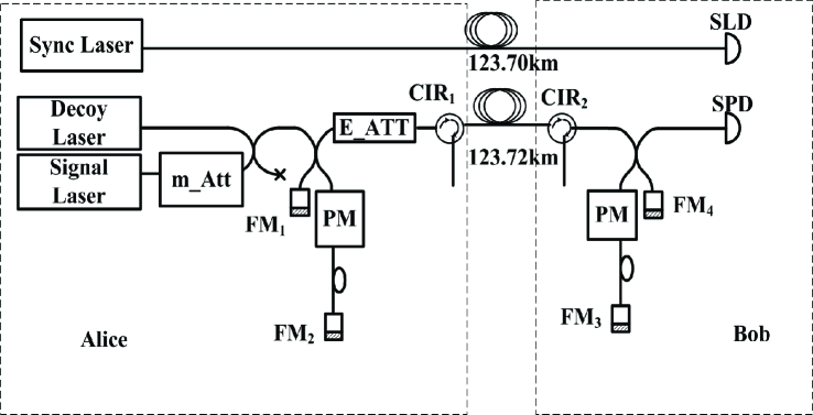
Alice randomly triggers the decoy or signal laser diode (DFB laser diodes) to emit decoy laser pulse or signal laser pulse (quantum light for abbreviation) and drives synchronization laser diode to emit synchronization laser pulse at the same time. After emitted from Alice, quantum light enters Alice’s Faraday-Michelson interferometer, attenuated by electrical variable optical attenuator (EVOA) to proper intensity (average photon number per pulse: 0.6 for signal pulses, and 0.2 for decoy signal pulses), enters 123KM single mode fiber (quantum channel), phase-modulated by Bob’s Faraday-Michelson interferometer and is detected by Bob’s SPD at last. Synchronization laser pulse goes through another single mode fiber (synchronization channel) which is almost as long as quantum channel. After emitted from Alice, synchronization laser pulse enters synchronization fiber immediately, in a while is detected by SLD, and then SLD gives a signal to notify control board of Bob. Then Bob’s control board makes his phase modulator get ready for this operation, and after a subtle delay, control board of Bob generates a trigger signal to SPD, which detect the quantum light pulse and tell the result to control board. After all operations finished, Alice announces decoy and signal information and phase modulation information through classical communication. According to this information, Bob calculates , and then , through equation (1) and (2). Now we can perform error correction and privacy amplification to get unconditionally secure key. The structure of our two-intensity decoy QKD system is demonstrated on figure 1.
Intensity Modulation: How to realize laser pulse intensity modulation is first step to perform decoy state QKD. Through making simple modifications to the ordinary QKD system to realize intensity modulation is very important to widen the use of decoy state QKD. In our experiment, we use two laser diodes method to realize laser pulse intensity modulation. We add a manual optical attenuator to one of laser diode output. Then a fiber optical beam splitter is used to couple the two laser output. We carefully adjust the manual optical attenuator to make sure ratio of the two laser pulse intensity is 1:3. Now, we can modulate intensity through selecting different laser diode. With changing voltage on EVOA, we can also modulate the intensity of laser pulse, but the repetition frequency of EVOA is too low. Two laser diodes method is very convenient and able to work with high repetition frequency.
Synchronization: Synchronization, especially to find the precision delay between synchronization laser pulse and quantum light pulse is very important to lower the QBER. The timing jitter of our SLD is less than 500ps, while the gate-width of SPD is 2.5ns. So the QBER caused by timing jitter is deeply depressed.
Phase Modulation: How to precisely determine the phase modulation voltage is essential for lowering QBER. Because of environmental disturbance, the phase modulation voltage may drift randomly. To avoid the influence of this drift, we use active phase compensation scheme. According to the half-wave voltage of Alice’s phase modulator, Alice can set her phase modulation voltage (for , , and ) definitely. Before transferring laser pulses for generating key, Alice sets an arbitrary phase modulation voltage, and then emits strong laser pulses to the quantum channel, then Bob scans the whole possible phase modulation voltage and watches the counting rates from SPD. According to results of this scan, Bob can determine his phase modulation voltage (for , , and ). The time spent to determine phase modulation working points relies on the drift speed of interferometers. In common, the ratio between time spent to determine phase modulation working points and the total working time is below 5%.
III Results&Conclusion
Experiment Results: We set , average photon number for signal laser pulses and for decoy laser pulses. The ratio of decoy laser pulse number and signal laser pulse number is 1:1, and 2G laser pulses was emitted in total. Table I is the results for the experiment. With the experiment results, equation (1), (2) and (3), we can get , , and . In table II, the length verse , , and are given. In Figure 2, a graph on the length verse are given too.
| Length (KM) | ||||
|---|---|---|---|---|
With the experiment results, equation (2) and (3), we can get , , and . In table II, the length verse , , and are given. In Figure 2, a graph on the length verse are given too.
| Length (KM) | |||
|---|---|---|---|

Form Figure 2, we find the limited fiber distance is about 130KM. We have successfully realized up to 130KM decoy states QKD protocol just with simple two-intensity protocol on one-way Faraday-Michelson phase modulation system. And really unconditionally secure key can be distributed through such a long distance fiber.
In conclusion, we have implemented two-intensity decoy QKD protocol on the one-way Faraday-Michelson phase modulation QKD system with a popular avalanche photon diode detector. Unlike many other QKD systems which is suffered of disturbances of transmission channel, one way Faraday-Michelson QKD system, which is free of polarization disturbances caused by quantum channel and optical devices in the system, can really keep steady and high interference fringe visibility, and leads to low QBER. With low and steady QBER, both security distance and key bit rate of decoy state QKD are improved. It’s noticeable that one way Faraday-Michelson QKD system free of channel disturbances can be used directly in commercial condition not only in lab. Our system can provide unconditionally secure key distribution service up to 130KM optical fiber on telecom wavelength (1550nm). So far, this distance is longest in real-life two-intensity decoy state QKD systems.
The authors thank Dr.Chi-Hang Fred Fung and Prof.Hoi-Kwong Lo for reading the manuscript and helpful advice. This work was supported by National Fundamental Research Program of China (2006CB921900), National Natural Science Foundation of China (60537020,60621064) and the Innovation Funds of Chinese Academy of Sciences. To whom correspondence should be addressed, Email: zfhan@ustc.edu.cn.
References
- (1) C. H. Bennett, G.Brassard, Proceedings of IEEE International Conference on Computers, Systems, and Signal Processing, (IEEE, 1984), pp. 175-179.
- (2) A. K. Ekert, Phys. Rev. Lett. 67 661 (1991)
- (3) N. Gisin, Gr goire Ribordy, W. Tittel, and H. Zbinden Rev. Mod.Phys. 74, 145 (2002)
- (4) M. Bourennane et al., Opt. Express 4, 383 (1999)
- (5) D. Stucki et al., New. J. Physics, 4, 41, (2002)
- (6) H. Kosaka et al., Electron. Lett. 39, 1199 (2003)
- (7) C. Gobby, Z.L. Yuan, and A.J. Shields, Appl. Phys. Lett. 84, 3762 (2004);
- (8) X.-F. Mo, B. Zhu, Z.-F. Han, Y.-Z. Gui, G.-C. Guo, Optics Letters, Vol. 30, Issue 19, pp. 2632-2634 (October 2005)
- (9) Z.-F. Han, X.-F. Mo, Y.-Z. Gui, and G.-C. Guo, Appl Phys Lett 86,
- (10) P. M. Nielsen, C. Schori, J. L. Sensen, L. Salvail, I. Damgd, and E. Polzik, J. Mod. Opt. 48, 1921 (2001)
- (11) B.Huttner, N. Imoto, N. Gisin, and T. Mor, Phys. Rev. A 51, 1863 (1995);
- (12) G. Brassard, N. Lu tkenhaus, T. Mor, and B. C. Sanders, Phys. Rev. Lett. 85, 1330 (2000).
- (13) N. Lu tkenhaus, Phys. Rev. A 61, 052304 (2000).
- (14) W.-Y. Hwang, Phys. Rev. Lett. 91, 057901 (2003).
- (15) H.-K. Lo, X. Ma, and K. Chen, Phys. Rev. Lett. 94, 230504 (2005).
- (16) X.-B. Wang, Phys. Rev. Lett. 94, 230503 (2005);
- (17) X. Ma et al., Phys. Rev. A 72, 012326 (2005).
- (18) Y. Zhao, B. Qi, X. Ma, H.-K. Lo, and L. Qian Phys. Rev. Lett. 96, 070502 (2006)
- (19) C.-Z. Peng, J. Zhang, D. Yang, W.-B. Gao, H.-X. Ma, H. Yin, H.-P. Zeng, T. Yang, X.-B. Wang, and J.-W. Pan Phys. Rev. Lett. 98, 010505 (2007)
- (20) D. Rosenberg, J. W. Harrington, P. R. Rice, P. A. Hiskett, C. G. Peterson, R. J. Hughes, A. E. Lita, S. W. Nam, and J. E. Nordholt Phys. Rev. Lett. 98, 010503 (2007)
- (21) Tobias Schmitt-Manderbach et al. Phys.Rev.Lett 98, 010504 (2007)
- (22) Yi Zhao, Bing Qi, X.-F. Ma, H.-K. Lo, Li Qian Proceedings of IEEE International Symposium on Information Theory 2006, pp. 2094-2098 Z.
- (23) L. Yuan, A. W. Sharpe, and A. J. Shields Appl. Phys. Lett. 90, 011118 (2007)
- (24) Vadim Makarov, Andrey Anisimov, and Johannes Skaar Phys. Rev. A74, 022313 (2006)
- (25) A. Vakhitov, V. Makarov, and D. R. Hjelme, J. Mod. Opt. 48, 2023 (2001)
- (26) N. Gisin, S. Fasel, B. Kraus, H. Zbinden, and G. Ribordy, Phys. Rev. A 73, 022320 (2006)