Coherent control of broadband vacuum squeezing
Abstract
We present the observation of optical fields carrying squeezed vacuum states at sideband frequencies from 10 Hz to above 35 MHz. The field was generated with type-I optical parametric oscillation below threshold at 1064 nm. A coherent, unbalanced classical modulation field at 40 MHz enabled the generation of error signals for stable phase control of the squeezed vacuum field with respect to a strong local oscillator. Broadband squeezing of approximately dB was measured with balanced homodyne detection. The spectrum of the squeezed field allows a quantum noise reduction of ground-based gravitational wave detectors over their full detection band, regardless of whether homodyne readout or radio-frequency heterodyne readout is used.
pacs:
42.50.Dv, 04.80.Nn, 42.65.Yj, 42.50.LcI Introduction
Quantum noise is one of the limiting noise sources in laser interferometers and appears as an uncertainty of the light field’s quadratures, which carry the signal of the interferometric measurement. For coherent laser radiation the quantum noise is minimal, and symmetrically distributed among pairs of noncommuting field quadratures. The finite, non-zero value of this so-called vacuum noise is a manifestation of Heisenberg’s uncertainty relation (HUR). However, for certain nonclassical states of light the quantum noise can be asymmetrically distributed among field quadratures, such as amplitude and phase quadratures. In the case of squeezed states Wal83 , the quantum noise of one quadrature is reduced below vacuum noise, whereas the quantum noise in the orthogonal quadrature is increased without violating the HUR. Since an interferometer measures a certain, single quadrature of the field, an appropriately squeezed field can improve the signal-to-noise ratio in a quantum-noise-limited interferometer.
The application of squeezed states in laser interferometers was first proposed by Caves Cav81 in 1981. Motivated by the challenging effort at the direct observation of gravitational waves Thorne87 , Caves suggested injecting squeezed vacuum states of light into the dark signal port of interferometric gravitational wave detectors. The goal of that proposal was the reduction of the vacuum noise of the interferometer’s readout laser beam, which is often called shot noise. Two years later Unruh Unruh82 realized that squeezed light can be used to correlate interferometer shot noise and radiation pressure noise (back-action noise) in such a way that the so-called standard quantum limit can be broken, and a quantum nondemolition measurement on the mirror test mass position can be performed. For an overview we refer the reader to Ref. KLMTV01 . The theoretical analysis of Harms et al. HCCFVDS03 further motivated research on squeezed states. They found that advanced interferometer recycling techniques Mee88 that also aim for an improvement of the signal-to-shot-noise ratio are also fully compatible with squeezed-field injection.
The first observation of squeezed states was done by Slusher et al. SHYMV85 in 1985. Since then different techniques for the generation of squeezed light have evolved. One of the most successful approaches to squeezed-light generation is optical parametric oscillation (OPO). Hence common materials like MgO:LiNbO3 can be used to produce broadband squeezing at the carrier wavelength of today’s gravitational wave (GW) detectors (1064 nm). In the future, various recycling techniques as well as the most powerful single-mode lasers available will be used to reduce the quantum noise in GW detectors. It is generally expected that the interferometer sensitivities will be limited by shot noise in the upper audio band and by radiation pressure noise in the lower audio band Shoemaeker03 . At intermediate frequencies, both quantum noise and thermal noise BGV99 are expected to dominate the overall noise floor. Therefore squeezing of quantum noise indeed offers a further increase of GW detector sensitivities.
Gravitational wave detectors require a broadband squeezed field in the detection band from about 10 Hz to 10 kHz. If a radio-frequency (rf) heterodyne readout is used, squeezing in the band of 10 kHz around twice the rf-phase modulation frequency is also required GLe87 . Furthermore, GW detectors utilize recycling cavities, implying that the orientation of the squeezing ellipse needs to be designed for every sideband frequency. The transformation from frequency-independent squeezing to optimized frequency-dependent squeezing can be performed by optical filter cavities, as proposed in KLMTV01 and demonstrated in CVHFLDS05 . The combination of squeezed-field injection and optimized orientations of squeezing ellipses, as well as power recycling and signal recycling of interferometers, has been demonstrated in VCHFDS05 ; VCHFDS06CQG . Squeezed states at audio frequencies have been demonstrated recently MGBWGML04 ; MMGLGGMM05 ; VCHFDS06 .
Applications of squeezed states generally require active phase control with respect to the local oscillator field of the readout scheme. Controlling the squeezed fields is indeed the basic problem for squeezed-field applications in GW detectors. Common control schemes rely on the injection of a weak, phase-modulated seed field at the carrier frequency into the OPO, thereby turning the device into an optical parametric amplifier (OPA). It has been shown that even the lowest carrier powers introduce too large amounts of classical laser noise at audio frequencies, and squeezing can no longer be achieved MGBWGML04 . On the other hand, phase modulation sidebands are not present in a pure vacuum field. For this reason a coherent control field could not be created in MGBWGML04 for either the squeezed-field carrier frequency or the relationship between the squeezed quadrature angle and local oscillator. The quadrature angle was locked instead using so-called noise locking, whose stability was found to be significantly less than what can be achieved with coherent modulation locking MMGLGGMM05 as used in GW interferometers.
In this paper we report on the generation and coherent control of broadband squeezing from subaudio frequencies up to radio frequencies. The coherent control scheme that was first used in VCHFDS06 is presented in detail.
II Control Scheme
All current interferometric gravitational wave detectors are Michelson interferometers operating close to a dark fringe at the signal output port. The optical field at the output port consists of a local oscillator field that beats with modulation sideband fields at frequencies generated by gravitational waves and (quantum) noise. In homodyne detection, the local oscillator has the same optical frequency as the main interferometer laser field. In heterodyne detection the local oscillator consists of a combination of upper and lower modulation sideband fields at frequencies . Both detection schemes provide eigenvalues of the time-dependent quadrature operator , where is the resolution bandwidth (RBW) and the quadrature angle. The angle might be chosen to select the quadrature with the optimum signal-to-noise ratio. In the following we will refer to the amplitude quadrature () and the phase quadrature () with the subscripts 1 and 2. For vacuum fields, the variances of the quadrature operators are typically normalized to unity and the Heisenberg uncertainty relation sets the following lower bound for the product of the quadrature variances:
| (1) |
For a broadband amplitude-squeezed field, is always below the unity vacuum noise reference for all sideband frequencies within the squeezing band. The HUR requires that in this case is greater than unity by a factor of at least the inverse of the squeezed quadrature variance. A squeezed vacuum field is said to be pure if, for all sideband frequencies in a certain band, the equals sign holds in Eq. (1). If a pure, squeezed vacuum field senses optical loss due to absorption or scattering, the squeezed field gets mixed with the (ordinary) vacuum field. In that case the equals sign in Eq. (1) is no longer realized; however, we still speak of a squeezed vacuum field or just vacuum squeezing.
For the application of a squeezed vacuum field in an interferometer, the squeezed quadrature needs to be matched to the interferometer readout quadrature. To achieve this goal the OPO cavity needs to be length controlled to resonate for the carrier frequency . Furthermore, the wave front of the second-harmonic OPO pump field has to be phase controlled with respect to the interferometer readout field. Note that the phase of the OPO pump field determines the phase of the squeezed field. Both control requirements mentioned can easily be realized if a radio-frequency phase-modulated field at carrier frequency, that is sent through the OPO cavity, can be utilized. If such a field cannot be applied, for example because its noise prevents the observation of squeezed states, coherent control is much more difficult to achieve. In this section we discuss in detail the coherent control scheme that was first used in VCHFDS06 .
Our scheme uses control fields that are coherent with the squeezed field without interfering with it. The latter ensures that noise from the control fields does not deteriorate the nonclassical performance of the squeezed field. Altogether two coherent control fields are required. Both are frequency shifted against the carrier frequency . A coherent, frequency-shifted field can be generated by an independent but phase-locked laser source or by an acousto-optical modulator (AOM) acting on a tapped laser beam from the same source. The first frequency-shifted control field enables length control of the OPO cavity. It carries radio-frequency phase modulation sidebands, is orthogonally polarized with respect to the squeezed vacuum field, and is injected into the OPO cavity. The frequency shift should exactly compensate the birefringence of the nonlinear crystal such that both control field and squeezed field simultaneously resonate in the OPO cavity. The frequency shift as well as the orthogonal polarization prevents the interference of the squeezed vacuum field and the control field.
The control of the quadrature angle of the squeezed vacuum with respect to a local oscillator or an interferometer carrier field is more challenging. This request is achieved by the second control field (quadrature control field, QCF) which is also injected into the OPO cavity. This field does sense the OPO nonlinearity but is frequency shifted against the vacuum squeezed mode. The QCF allows the generation of two individual error signals for two different servo control loops. The first error signal is used to control the relative phase between the QCF and the OPO pump field. The second error signal is used to control the relative phase between the OPO pump field and the local oscillator field of the interferometer, or rather the homodyne detector. The combination of both error signals provides the means to stabilize the quadrature of the squeezed vacuum field with respect to a local oscillator.
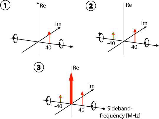
In the following we show that the required error signals can be gathered from the QCF leaving the OPO cavity, and from the interference of the QCF with the local oscillator field at the homodyne detector. We label those two error signals and , respectively, and first derive an expression for the parametrically amplified quadrature control field QCF. Before parametric amplification the QCF at optical frequency represents a single sideband field with respect to the carrier frequency (see ➀ in Figs. 1 and 2). In the following we describe this field by the real-valued amplitude . The expectation values of the annihilation operators of the upper and lower sideband fields at frequencies may then be written as follows:
| (2) |
The quadrature amplitudes CSc85 are given by
| (3) |
Here all quantities are defined for discrete frequencies. This simplifies our description and is reasonable because the bandwidth of the error signals is small compared to .
The OPO acts on these quadrature amplitudes in different ways. If it amplifies the phase quadrature then it deamplifies the amplitude quadrature, and vice versa. Mathematically, this effect of amplification and deamplification of the quadratures can be described with the use of the squeezing operator with squeezing factor and squeezing angle (see CSc85 ). The resulting squeezed quadrature vector is given by:
| (4) |
where and .
The expectation values of the new squeezed quadrature amplitudes and take the following form
| (5) |
To derive the corresponding electrical field
| (6) | ||||
| with | ||||
| (7) | ||||
we need the Fourier transformations of and . Since we consider a single frequency we obtain
| (8) |
By choosing we simplify our expression and find for the outgoing QCF from the OPO
| (9) |
This is the desired expression for the parametrically amplified QCF, and forms the basis for the following derivation of the two error signals and . One can easily see in Eq. (II) that is composed of two sidebands that are equally separated by from the carrier frequency . This is also illustrated in the sideband scheme ➁ in Fig. 2. The quadrature where these two sidebands beat with each other can be chosen using the squeezing angle . If one uses a squeezing angle of the following electrical field is found:
| (10) |
which has also been provided in VCHFDS06 .
Detection of the outgoing field from the OPO with a single photo diode results in the following photocurrent:
| (11) |
Demodulating with frequency and subsequent low-pass filtering provide the error signal for the relative phase between the second-harmonic pump field and the QCF, given in terms of the squeezing angle
With an appropriate demodulation phase one obtains the sinusoidal error signal
| (12) |
Now that we are able to stabilize with respect to the QCF, the first step to a complete coherent control of a squeezed vacuum generated by an OPO is satisfied.
In a second step the phase between the second-harmonic pump field and the local oscillator needs to be controlled. The error signal is generated from the difference current of the two homodyne photodiodes PD. Overlapping the local oscillator field with the outgoing QCF from the OPO at the LO homodyne beam splitter results in two homodyne detector fields and which are individually detected with a single photodiode. The complex field amplitudes of one of the homodyne detector fields can be seen graphically in Fig. 2,➂. Mathematically they are given by
| (13) |
| (14) |
The difference current of the induced photocurrents is then given by
| (16) |
where Eq. (16) is the difference of the photocurrents after low-pass filtering. The demodulation of with and again low-pass filtering results in the error signal for the relative phase between the second-harmonic pump and the local oscillator
| (17) |
This error signal depends not only on the relative phase between the second-harmonic pump and the local oscillator , but also on the squeezing angle . However, it becomes clear that the combination of both error signals according to Eqs. (12) and (17) enables full coherent control of the squeezed vacuum generated by an OPO with respect to the local oscillator of a downstream experiment.
III Experimental Setup and Results
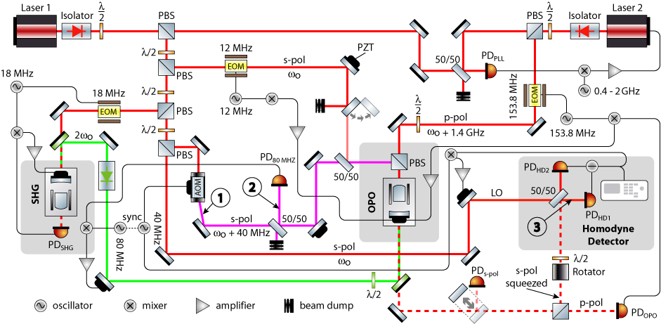
Figure 1 shows the schematic of our experimental setup that was used to demonstrate coherently controlled broadband vacuum squeezing. Altogether two independent, but phase locked laser sources (lasers 1 and 2) were utilized. Both were monolithic nonplanar neodymium-doped yttrium aluminum garnet (Nd:YAG) ring laser of 2 and 1.2 W single-mode output powers at 1064 nm, respectively. Approximately 1.4 W of laser 1 was used to pump a second-harmonic-generation (SHG) cavity. The design of the SHG cavity was the same as for our OPO cavity. The two differed only in the reflectivities of the outcoupling mirrors.
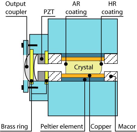
A detailed sketch of our SHG and OPO cavity design and mounting is shown in Fig. 3. We used a hemilithic layout which was formed by an outcoupling mirror and a highly reflection-coated crystal back surface. The oven was made of an aluminum surrounding that houses the crystal and the Peltier elements and served as a heat sink. The outcoupling mirror together with the piezoelectric transducer (PZT) and a Viton ring formed a stack that was clamped together with an aluminum cap. This stack was located in an aluminum plate that was bolted onto the aluminum surrounding of the oven. Macor blocks were used to thermally shield the crystal from outside. The Macor blocks had two small holes on the optical axis for the laser beam. A servo loop was used for active temperature stabilization of the crystal. The required temperature sensor was embedded into the copper plates and the servo feedback was put on the peltier elements. The OPO as well as the SHG crystal were made from 7% doped MgO:LiNbO3 and had the dimensions 2.556.5 mm3. The curved back surface of the crystals had a high-reflection coating (=99.96%) whereas the flat surface had an antireflection coating (0.05%) for both wavelengths. The cavities had a free spectral range of approximately GHz. The crystals were mounted into the ovens in such a way that s-polarized fields could sense the nonlinearity
The SHG used an outcoupling mirror with power reflectivities of and . The cavity length was controlled using the Pound-Drever-Hall (PDH) locking scheme with a phase modulation at a sideband frequency of 18 MHz. The generated second-harmonic field had a power of up to 500 mW.
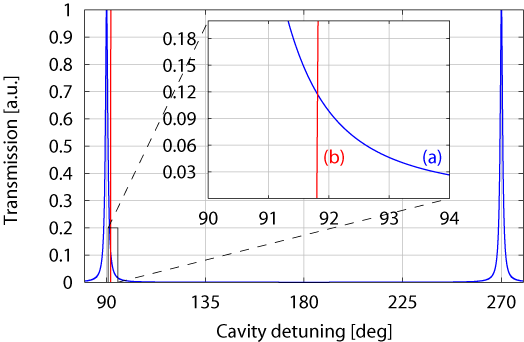
The OPO cavity utilized an outcoupling mirror with power reflectivities of and . This resulted in a linewidth of 28.9 MHz at 1064nm (see Fig. 4). For the OPO or OPA two different control loops for stabilizing the cavity length were set up. The first cavity length control loop was used during alignment of our experiment. It utilized a resonant s-polarized seed beam that carried phase modulation sidebands at a frequency of 12 MHz for a PDH locking scheme. The error signal could be generated using either the sum of the homodyne detectors or an additional detector placed in transmission of the OPA (see Fig. 1). The latter detector was also used to determine the frequency offset between the s- and p-polarized laser beams inside the OPA or OPO. The error signal was fed back to the PZT-mounted output coupler. The second cavity length control loop was used for the generation of squeezed vacuum states at low frequencies, since the first control loop introduced too much noise at low frequencies (see Sec. II). This control was realized with a p-polarized field generated by the second monolithic nonplanar Nd:YAG ring laser (laser 2). Due to the birefringence of the MgO:LiNbO3 crystal the ’s of the OPO cavity for s- and p-polarization are not degenerate. To ensure that both polarizations resonate simultaneously in the cavity we shifted the frequency of the p-polarized field. We determined the frequency shift to be about 1.4 GHz. The frequency offset was controlled via a phase-locking loop (PLL) that could be operated from nearly DC up to 2 GHz with a bandwidth of several kilohertz. The error point of the PLL was fed back to the PZT of the second laser. Phase modulation sidebands at a frequency of 153.8 MHz were imprinted onto the p-polarized field, which was then injected through the back surface of the OPO crystal. The transmitted part was spatially separated from the s-polarized squeezed vacuum with a polarizing beam splitter (PBS) and detected by the photodetector. A PDH locking technique was used to generate an error signal which was fed back to the PZT of the OPO cavity.
Following our proposal described above we utilized a second coherent but frequency-shifted control field for the phase control of the squeezed vacuum field, detuned by with respect to the main carrier frequency (, laser 1) by an AOM [see Eq. (3) & ➀ in Figs. 1 and 2]. The frequency of the AOM was MHz. This frequency-shifted s-polarized infrared QCF (440 W) was also injected into the OPO cavity through the crystal’s back surface. It therefore had to be spatially overlapped with the p-polarized locking beam using a 50/50 beam splitter. To eliminate technical noise below 1 kHz in the homodyne spectra, the zero order of the AOM had to be blocked carefully. If only small fractions of this non-frequency-shifted field leaked into the cavity, the squeezing spectrum was spoiled by the large technical noise in the low-frequency regime.
Figure 4 shows that only 11.5% of the QCF was coupled into the cavity. This 11.5% interacted with the pump field inside the cavity, its quadratures were parametrically amplified and deamplified, and an additional sideband at MHz [see Eq. (II)] was generated. This outgoing QCF from the OPO then consisted of two sidebands, each separated by 40 MHz from the carrier frequency (see ➁ in Figs. 1 and 2). The error signal could be obtained by detecting the outgoing QCF from the OPO and demodulating the photocurrent at 80 MHz as illustrated in the sideband scheme in Figs. 1 and 2. By feeding back the error signal to a PZT-mounted mirror in the path of the second-harmonic pump field, stable control of was realized [see Eq. (12)]. The error signal for controlling the homodyne angle [see Eq. (17)] was derived at the homodyne detector. The difference of the two photodiode currents was demodulated with a frequency of 40 MHz. The output of this servo loop was fed back to a PZT-mounted mirror in the local oscillator path.
The homodyne detector was built from a p-polarization-optimized 50/50 beam splitter and two electronically and optically matched photodetectors based on Epitaxx ETX500 photodiodes. The angular orientation of the photodiodes was optimized to achieve the maximum power to optimize the detection efficiency. We used two different pairs of matched photodetectors: one was optimized for the low-frequency regime whereas the other pair was optimized for high bandwidth. In all measured spectra shown here the electronic noise of the detection system was subtracted from the measured data.
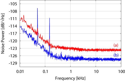
The low-frequency-optimized homodyne photodiode pair permits the measurement of the low-frequency spectrum of the OPO (see Fig. 5) in the detection bandwidth of GW interferometers and above up to 100 kHz. For these low-frequency measurements we used a nominal local oscillator power of 88 W. The resulting shot-noise limit of the homodyne detection system is shown as curve (a) in Fig. 5, whereas the squeezed quantum noise is shown in curve (b). During the measurement period of approximately 1.5 h the complete experiment including the OPO with all its related control loops, was controlled stably in all degrees of freedom. For the measurements in Fig. 5 a parametric gain of 10 was used, which was obtained using 60 mW of the second-harmonic pump field. The propagation losses of the squeezed vacuum were dominated by the Faraday rotator passthrough efficiency of only 95%. The mode matching efficiency between the local oscillator and the squeezed field was measured to be 94.3%. Altogether this allowed us to measure 4 dB squeezing over the complete detection band of ground-based GW interferometers.
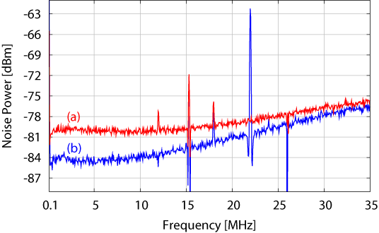
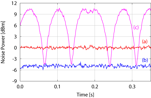
The OPO squeezing spectrum from 100 kHz to 35 MHz is shown in Fig. 6. Curve (a) shows the shot-noise limit of the homodyne detector, while the squeezing spectrum is shown in curve (b). Both traces take the dark noise into account. These measurements were done with the high-bandwidth-optimized homodyne detector using a local oscillator power of 8.9 mW. The resulting shot noise showed a nonwhite behavior above 10 MHz. This stemmed from small deviations in the transfer functions of the two homodyne photodetectors used. One can see that up to 10 MHz we observed at least 4 dB of squeezing, peaking around 5 MHz with up to 4.95 dB of squeezing (see Fig. 7). At higher frequencies the squeezing degraded to approximately 1 dB due to the linewidth of the OPO cavity. Lowering the finesse of the OPO would open up the high-frequency regime for a better squeezing performance, but higher pump powers would be needed to produce the same amount of squeezing.
The two individual measurements show that we have produced 4 dB of squeezing over more than six decades from 10 Hz up to 10 MHz.
IV Application to Gravitational Wave Detectors
In VCHFDS06 a broadband squeezed vacuum field was applied to a simple Michelson interferometer. A nonclassical signal-to-shot-noise improvement was observed using balanced homodyne detection. However, real gravitational wave Michelson interferometers are much more complex. Here we discuss two aspects that are important when coherently controlled broadband squeezed vacuum fields are applied to signal-recycled gravitational wave detectors with heterodyne readout.
In an application to a gravitational wave detector, the quadrature control field, here shifted in frequency by MHz, will enter the interferometer from the dark port together with the squeezed field Cav81 ; SHSD04 . The best choice for the QCF frequency is such that it is offresonant with respect to the signal-recycling cavity (SRC). In this case the QCF is basically reflected from the SRC, which minimizes possible disturbances to other interferometer control loops. A generally rather important interferometer control field stabilizes the Michelson interferometer on a defined differential arm length to provide the desired dark signal port condition. In GEO 600 this control field operates at a sideband frequency of 14.9 MHz and is photoelectrically detected in the dark port. Obviously, the QCF frequency should also provide a sufficiently large offset from that frequency of 14.9 MHz. Our choice of MHz is therefore rather practical in the case of GEO 600.
Another aspect is the compatibility of the squeezed vacuum field demonstrated here and the heterodyne detection scheme that is currently used in all gravitational wave detectors, namely GEO 600 geo04 ; geo06 , LIGO LIGO ; geo04 , TAMA 300 TAMA , and VIRGO VIRGO04 . Gea-Banacloche and Leuchs GLe87 have shown that an interferometer with heterodyne readout requires squeezing in the band of expected gravitational wave signals () and also squeezing around twice the heterodyne frequency (). This is because the noise at contains vacuum noise contributions from . It was later shown that these results are still valid for detuned signal-recycled interferometers CDRGBM98 .
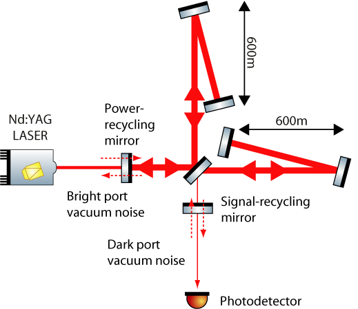
The realization that broadband squeezing up to is needed to gain the full sensitivity enhancement from squeezing leads to the question as to where one should inject the squeezed vacuum field. Figure 8 shows a schematic of GEO 600. In normal operation the interferometer behaves like an almost perfect mirror for the carrier light entering from the bright port and for vacuum fluctuations entering from the dark port. Due to a small, but macroscopic, difference of the two arm lengths, which is needed for the Schnupp modulation Schnupp88 , the reflectivity of this mirror is frequency dependent. Thus, the amplitude reflectivity changes at different sideband frequencies, relative to the carrier frequency. The decision as to which interferometer port the squeezed states will be injected into, is therefore dependent on the sideband frequency.
We can distinguish between three different cases. First, the interferometer has high reflectivities in the two interesting frequency regions: . If so, we can inject the squeezed states at all frequencies from the dark port. These will then be perfectly reflected and we obtain the full improvement from the squeezing.
The second case is that we have a high reflectivity at the signal frequency but high transmission at frequency , ; . If we still injected all the squeezed states from the dark port, we would lose the squeezing at , which results in a less sensitive interferometer. To solve this problem one might split the squeezed-light field in frequency space e.g. use a filter cavity. We then obtain a field that carries the low-frequency squeezing around and a second field that is squeezed around frequencies . The low-frequency squeezed field is injected through the dark port, whereas the second one has to be injected through the bright port together with the carrier field. This will then give the optimal performance increase one expects from using squeezed light. Instead of using a filter cavity, one might employ two independent sources of squeezed states with optimized nonclassical noise suppression in the audio and rf bands, respectively. The third case is that the interferometer reflectivity is still high at the signal frequencies, , but has an intermediate reflectivity, , near twice the modulation frequency. In this case the power fraction of has to be tapped off the high-frequency part of the squeezed field. This fraction has to be injected into the interferometer’s bright port, whereas the remaining fraction is injected into the dark port, together with 100% of the low-frequency part of the squeezed field. In this way the squeezed field at high frequencies senses a Mach-Zehnder-type configuration and constructively interferes in the interferometer’s (dark) signal port. Again the broadband squeezed field is optimally employed for a nonclassical sensitivity improvement of a gravitational wave detector with heterodyne readout. We note that in all these three cases one has to use frequency-dependent squeezed fields to compensate the phase shifts from the reflection at a detuned cavity HCCFVDS03 ; CVHFLDS05 .
GEO 600 currently uses a heterodyne frequency of 14.9 MHz. The reflectivity of the interferometer at this frequency is approximately 96% in power. Consider now a broadband vacuum squeezed field of 6 dB nonclassical noise suppression from 10 Hz up to 30 MHz injected into GEO 600’s dark port. Neglecting optical losses inside the interferometer, the squeezed states at gravitational wave signal frequencies are perfectly reflected. Those at twice the heterodyne frequency sense 4% loss, and their nonclassical noise suppression degrades from 6 to about 5.5 dB, which is still a useful value. Hence the injection of the complete broadband vacuum squeezed field into the dark port seems to be a reasonable approach in the case of GEO 600.
V Conclusion
We have reported on a control scheme for phase locking of squeezed
vacuum fields, generated by optical parametric oscillation, to a
local oscillator of a downstream experiment or of a homodyne
detector. Our scheme utilized two frequency-shifted control fields
that allowed us to control the length of the OPO cavity as well as
the angle of the squeezed-field quadrature. This control scheme
allowed stable generation and observation of broadband squeezed
fields covering more than six decades from 10 Hz to about
35 MHz. We discussed the application of our control scheme and
the broadband squeezed field generated for GEO 600, as an example
for a large-scale gravitational wave detector. We found that such
a squeezed field injected into the signal dark port
can improve GEO 600’s sensitivity beyond its shot-noise limit, even if the current heterodyne readout is used.
VI Acknowledgements
We thank Alexander Franzen, Boris Hage, and Jan Harms for fruitful
discussions.
This work has been supported by the Deutsche Forschungsgemeinschaft and is part of the Sonderforschungsbereich 407.
References
- (1) D. F. Walls, Nature 306, 141 (1983).
- (2) C. M. Caves, Phys. Rev. D 23, 1693 (1981).
- (3) K.S. Thorne, in 300 Years of Gravitation, edited by S.W. Hawking and W. Isreal (Cambridge University Press, Cambridge, England, 1987), pp. 330–458.
- (4) W. G. Unruh, in Quantum Optics, Experimental Gravitation, and Measurement Theory, edited by P. Meystre and M. O. Scully (Plenum, New York, 1983), pp 647–660.
- (5) H. J. Kimble, Y. Levin, A. B. Matsko, K. S. Thorne and S. P. Vyatchanin, Phys. Rev. D 65, 022002 (2001).
- (6) J. Harms, Y. Chen, S. Chelkowski, A. Franzen, H. Vahlbruch, K. Danzmann, and R. Schnabel, Phys. Rev. D 68, 042001 (2003).
- (7) B. J. Meers, Phys. Rev. D 38, 2317 (1988).
- (8) R. E. Slusher, L. W. Hollberg, B. Yurke, J. C. Mertz, and J. F. Valley, Phys. Rev. Lett. 55, 2409 (1985).
- (9) D. Shoemaker, Classical Quantum Gravity 20, S11 (2003).
- (10) V. B. Braginski, M. L. Gorodetsky, and S. P. Vyatchanin, Phys. Lett. A 264, 1 (1999).
- (11) J. Gea-Banacloche and G. Leuchs, J. Mod. Opt. 34, 793 (1987).
- (12) S. Chelkowski, H. Vahlbruch, B. Hage, A. Franzen, N. Lastzka, K. Danzmann, and R. Schnabel, Phys. Rev. A 71, 013806 (2005).
- (13) H. Vahlbruch, S. Chelkowski, B. Hage, A. Franzen, K. Danzmann, and R. Schnabel, Phys. Rev. Lett. 95, 211102 (2005).
- (14) H. Vahlbruch, S. Chelkowski, B. Hage, A. Franzen, K. Danzmann, R. Schnabel, Class. Quantum Grav. 23 S251 (2006).
- (15) K. McKenzie, N. Grosse, W. P. Bowen, S. E. Whitcomb, M. B. Gray, D. E. McClelland, and P. K. Lam, Phys. Rev. Lett. 93, 161105 (2004).
- (16) K. McKenzie, E. E. Mikhailov, K. Goda, P. K. Lam, N. Grosse, M. B. Gray, N. Mavalvala, and D. E. McClelland, J. Opt. B 7, S421 (2005).
- (17) H. Vahlbruch, S. Chelkowski, B. Hage, A. Franzen, K. Danzmann, and R. Schnabel, Phys. Rev. Lett. 97, 011101 (2006).
- (18) C. M. Caves and B. L.Schumaker, Phys. Rev. A 31, 3068 (1985)
- (19) R. Schnabel, J. Harms, K. A. Strain, and K. Danzmann, Class. Quantum Grav. 21, S1045 (2004).
- (20) S. Hild (for the LIGO Scientific Collaboration), Class. Quantum Grav. 23, S643 (2006).
- (21) B. Abbott et al., Nuclear Instruments and Methods in Physics Research Section A 517, 154 (2004).
- (22) A. Abramovici et al., Science 256, 325 (1992).
- (23) M. Ando et al., Phys. Rev. Lett. 86, 3950 (2001).
- (24) F. Acernese et al., Class. Quantum Grav. 21, S709 (2004).
- (25) V. Chickarmane, S. V. Dhurandhar, T. C. Ralph, M. Gray, H.-A. Bachor, and D. E. McClelland, Phys. Rev. A 57, 3898 (1998).
- (26) L. Schnupp: talk at the European Collaboration Meeting on Interferometric Detection of Gravitational Waves (Sorrento, 1988).