Avalanches Injecting Flux into the Central Hole of a Superconducting MgB2 Ring
Abstract
Magneto-optical imaging was used to observe dendritic flux avalanches connecting the outer and inner edges of a ring-shaped superconducting MgB2 film. Such avalanches create heated channels across the entire width of the ring, and inject large amounts of flux into the central hole. By measuring the injected flux and the corresponding reduction of current, which is typically 15 %, we estimate the maximum temperature in the channel to be 100 K, and the duration of the process to be on the order of a microsecond. Flux creep simulations reproduce all the observed features in the current density before and after injection events.
pacs:
74.70.Ad, 74.25.Qt, 74.25.Ha, 74.78.Db, 68.60.DvI Introduction
In recent years it has become clear that instabilities are commonplace when magnetic flux penetrates superconductors. In particular, magnetic flux avalanches can abruptly penetrate thin superconducting samples in the form of tree or fingerlike patterns known as dendrites. Such avalanches were first observed in YBa2Cu3Ox, where they must be triggered by a sudden point-like heat-pulse Leiderer et al. (1993); Bujok et al. (1993). Since then spontaneous dendritic avalanches have been observed Durán et al. (1995); Rudnev et al. (2003); Welling et al. (2004); Wimbush et al. (2004); Rudnev et al. (2005) in Nb, Nb3Sn, YNi2B2C and NbN, as well as in patterned Pb thin films Menghini et al. (2005). The recent interest in the phenomenon was largely triggered by the discovery Johansen et al. (2001) that in MgB2 films the avalanches are ubiquitous below a threshold temperature K. The dendrites disrupt electrical current flow and limit the overall current capacity of superconductors, Zhao et al. (2002) and are thus harmful for prospective applications. On the other hand they also represent fertile ground for fundamental research as there are many interesting challenges in understanding their nucleation and growth.
The dendritic instability is now believed to be of thermo-magnetic origin. Motion of flux in superconductors releases heat and increases the temperature. Flux motion is facilitated by the increase in temperature, so more flux moves which then leads to even more heating. If the released heat is not transported away fast enough an instability develops whereby large amount of magnetic flux rushes into the sample. This mechanism was originally invoked to explain global flux jumps where the entire sample is filled with a sudden burst of magnetic flux and all magnetisation is lost Swartz and Bean (1968); Mints and Rakhmanov (1981); Mints and Brandt (1996). However, the mechanism has recently also been shown to give localised, fingering instabilities. Aranson et al. (2005); Denisov et al. (2006a) Indeed, the instability threshold field predicted from this model was recently Denisov et al. (2006b) shown to agree quantitatively with measurements in both Nb and MgB2 films.
The dynamics of dendritic avalanches is extremely challenging to probe experimentally because of the short times involved. Typically the entire process of nucleation and growth of a single flux dendrite lasts a few hundred nano-seconds as measured using a sophisticated magneto-optical (MO) set-up Leiderer et al. (1993); Bujok et al. (1993). It is particularly difficult to measure the expected increase in temperature associated with the avalanches. On the other hand, it is possible to estimate the temperature in the dendrite indirectly by designing a suitable geometry where dendritic avalanches can leave a long-lasting, temperature dependent imprint. In particular, in superconducting rings dendrites may span the entire ring width and thus create a heated channel that connects the inner and outer edges. During the brief time that this channel is open it injects flux into the otherwise screened central hole in a process which may be described as magnetic perforation. This process depends on the temperature in the channel, which may then be inferred from measurements of the flux contained in the hole.
In this paper we report a detailed study on the perforation process in a superconducting MgB2 ring using MO imaging. The technique, described in section II, provides us with a detailed map of the flux distribution over a sample-wide area. In section III we present our experimental results, showing the evolution of the flux contained within the screened region during field ramps at different temperature, as well as the current distribution in the ring. displays abrupt jumps when dendrites cross the ring. From a simple model presented in section IV which connects the temperature evolution in the heated channel and the evolution of the current during perforations we estimate the peak temperature during flux injection. We find that this temperature is , and that the duration of the flux injection process is on the order of one s. Finally in section V we propose a numerical model to describe how the perforation affects the current distribution in the ring.
II Experimental set-up
A MgB2 ring was prepared by pulsed laser deposition (PLD) on a sapphire substrate. Details of the manufacturing process and typical properties of the superconductor can be found elsewhere Kang et al. (2001); Choi et al. (2005). Using photolithography the superconducting film of thickness m was patterned into a ring with inner radius mm and outer radius mm.
The magneto-optical indicator was a ferrite garnet film (FGF) of thickness 5 m grown on a gadolinium gallium garnet (GGG) substrate and covered with an Al mirror. Monodisperse beads (diameter 3.5 m) were sprinkled on the sample to ensure a small and uniform distance between the superconductor and the Al mirror prior to positioning of the indicator. This precaution is necessary since metallic layers are known to suppress dendritic avalanches Baziljevich et al. (2002); Choi et al. (2005) in MgB2. The entire stack was mounted in an optical cryostat (a liquid helium flow cryostat from Oxford Instruments) and cooled to low temperature for observation in a polarisation microscope. We ensured sensitivity to field direction by setting the polariser - analyser angle a few degrees away from full extinction. Images were captured with a QImaging Retiga Exi CCD camera with 12-bit pixel depth, controlled from a computer. The coil current was controlled from the same computer by means of a DAC card used to generate a control voltage to the current source. The computer also communicated with an external voltmeter (Hewlett Packard 34401A), which was used to monitor the coil current. The experiments were then conducted by slowly ramping the applied field from 0 to 25 mT while recording images at regular intervals. Each time an image was recorded, the coil current was read and written to a log file before proceeding with the field ramp.
We calibrated image brightness to field by capturing images at low temperature and a point away from the sample, while ramping the applied field from 0 to mT. The recorded applied field and the image brightness were used to fit a second-degree polynomial relating magnetic field to the image intensity. This polynomial form follows from Malus law for light intensity in a polarisation microscope,
| (1) |
along with the phenomenological linear relation for the Faraday rotation at small angles.
The calibration was performed pixel-by-pixel, which is necessary to account for uneven illumination in the field of view. The raw images were then processed in two stages: firstly, each image was converted to a field map using the obtained values of the fitting coefficients , and secondly the flux was computed by summing the field at each pixel contained within the relevant region.
Sensor noise leads to observable noise in the field values computed for each pixel, but summing over many thousand pixels to obtain the flux in a region effectively reduces random noise to insignificant levels. A more serious concern in quantitative magneto-optical measurements is systematic errors (see ref Jooss et al., 2002), particularly the existence of in-plane domains in indicator films which show up as triangular features of brighter and darker areas. The domain boundaries move easily in response to changes in temperature and applied field, and therefore result in a changing background. We minimised their influence by mounting the indicator very carefully on the sample to avoid mechanical stresses, and by applying a weak in-plane field. Despite these precautions domain splitting did occur in the experiments presented here. This was observed as dark regions slowly moving into the field of view during the field ramps, thus leading us to calculate a too low field value in the affected pixels. Fortunately, visual inspection of the images reveals that only a small part of the interesting region is affected, never more than % of the total area.
III Experimental Results
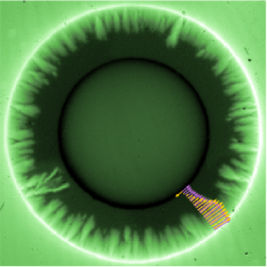
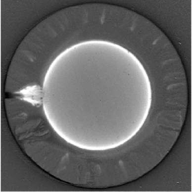
Figure 1 (a) shows an example field map recorded at K after applying a perpendicular field to the zero-field-cooled sample. Notice the negative field at the inner ring edge which is the accumulated stray field from the supercurrents. In the lower left quadrant of the ring we observe one of the relatively few, but also relatively large, dendrites formed at this temperature. In fact, the image shown here was the last taken prior to the nucleation and growth of a second dendrite which spanned the entire ring width and injected large amounts of flux into the central hole. This perforation event is illustrated in figure 1 (b) showing the difference between the frame in (a) and the subsequent frame taken at a slightly larger field. The increase in flux inside the central hole, and the accompanying reduction near the outer edge, are evident: the dendrite brings large amounts of flux from outside the sample into the central hole. Remarkably, as dramatic as the perforation event is, the flux distribution inside the superconducting material is left largely unchanged in the process.
Well below the threshold temperature we observe more frequent dendritic avalanches. At K the first dendrite appears at roughly mT. As reported previously Olsen et al. (2006) the size of individual dendrites increases with the applied field, until they span the entire ring and cause perforations.
For low applied fields, before the first perforation event occurs, the superconductor screens the area contained within , a characteristic radius where the flux fronts from the outer and inner edges meet in a critical state superconducting ring. The flux inside this region, , is the sum of the contribution from the supercurrents and the applied field :
| (2) |
Provided no perforations have occurred and the applied field is below the field of full penetration , this sum is exactly zero. Figure 2 shows the evolution of during ramps of the applied field at four different temperatures. For the highest temperature K (above the threshold for the onset of dendritic avalanches in the present experiment) the flux remains zero until the applied field reaches , after which it increases linearly with the applied field. The crossover results from the fact that the current in the superconductor has saturated and hence the term remains essentially constant when the applied field is increased further. The light gray oblique lines in figure 2 show slopes expected from the term. Guided by these lines one can see that the slope of the measured curve is slightly larger than expected if the supercurrents remained constant. This means there is some relaxation of the supercurrent in the ring as the applied field increases.
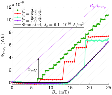
The central observation in this paper is seen in the curves obtained at temperatures below . is still zero up to a certain level, the perforation field, where it starts to increase in a step-like fashion, with sudden jumps followed by periods of screening. At K there are small and frequent jumps above the perforation field, which in this case is mT. The average slope of the flux curve corresponds to the flux increase due to the applied field, but is much smaller than for the normal critical state above . This means that the avalanches reduce the maximum total current which can flow in the ring.
The curves at K and K show similar behaviour, but with larger and fewer jumps and a slightly larger perforation field. In the latter case the jump occurs well after the field of full penetration has been reached.
Clearly the flux jumps are accompanied by an abrupt reduction of the total ring current, with a recovery taking place during the screening phases. However, it is not only the total current which is affected, but also the current distribution. Using an efficient inversion scheme based on the Biot-Savart law which takes advantage of the fast Fourier transform Roth et al. (1989), we obtain 2-D current distributions from our measured magnetic field maps. Superimposed on the field map in figure 1 (a) are two sets of arrows showing the direction and density of current just prior to and just after a perforation. In the former case the supercurrent is qualitatively what we expect in a critical state ring, with a saturated current in the flux penetrated part of the sample and a smaller screening current in the Meissner state region. The perforation profoundly changes this distribution. Near the outer edge there is a significant reduction in the current. Further from this edge, but within the flux penetrated region there is no discernible change in the current, while it is reduced throughout the Meissner region. However, the greatest change occurs close to the inner edge, where the current actually changes direction.
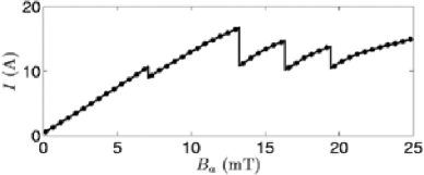
All these features are typical after perforation events. For the particular image sequence under discussion one can see the complete evolution of the current in figure 3. Each of the four perforations that occurred in the sequence are visible as distinct reductions in the current level, with most of the change occurring near the inner edge.
IV Peak temperature and duration of the perforations
The experiments give accurate measurements of the state just before and just after perforations. Despite the fact that the dynamics is far too quick for our experimental set-up, the fact that we can observe the change in allows us to make some qualified inferences about the details of the process. The starting point is to split the process into two phases: (i) the nucleation and growth phase when the dendrite tip rapidly moves from the outer to the inner edge creating a heated channel, and (ii) the flow phase when the resistive channel simultaneously impedes the supercurrents and injects flux into the central hole. We emphasise that during the first phase there should be little or no change in . Its duration is only determined by the dendrite tip velocity. Ultrafast MO measurements 11endnote: 1P. Leiderer, private communication has been used to measure the tip velocity of dendrites in MgB2 yielding a value m/s. This tip velocity gives a crossing time s in our sample.
The second phase is more involved. For a narrow ring or a uniform current distribution the evolution of the current can be expressed as a balance between the voltage drop across the heated channel and the induced emf voltage due to the change in the ring current:
| (3) |
is an ohmic resistance resulting either from a normal state resistivity above the critial temperature , or a flux flow resistivity originating from moving vortices, and is non-zero as long as the channel remains open. The inductance is a property of the ring, and is only determined by the geometry. The joule heating increases the temperature in the channel, a process which can be described by the heat equation
| (4) |
where we have ignored a term describing heat diffusion into the surrounding superconducting material. is the heat capacity, is the heat transfer coefficient to the substrate, and is the temperature of the substrate assumed to be equal to the cold finger temperature. The two equations are in fact coupled, since the current in the - term evolves according to equation (3). Moreover, the resistivity is strongly temperature dependent below , and hence the evolution of the current is influenced by the channel temperature. Physically, one can think of the process in the following way: as phase 2 commences the term dominates over the heat removal term leading to an increase in the temperature. But this has two consequences, both of which tend to oppose a further increase in temperature: firstly, the heat removal term becomes larger for higher temperature, and secondly the current is reduced in the ring and hence the heat generation is reduced. At some point heat removal equalises the heat generation and a maximum is reached, after which the temperature decreases until the current density drops below . At this point the resistivity vanishes, and the flux injection halts.
The fact that , and are all temperature dependent means an analytic solution is difficult to find. However, equation (4) can be used to estimate the maximum temperature during phase 2 directly by putting . Following ref Denisov et al., 2006b we write the heat transfer coefficient as and obtain the following equation for the maximum temperature
| (5) |
From figure 3 we find that at perforation the average current density over the whole ring is A/m2. The heat transfer coefficient was estimated in reference Denisov et al., 2006b to be kW/Km2 on samples manufactured in the same way on the same sort of substrate as the current sample. If the temperature is moderately above , the resistivity is independent of temperature in this material Eom et al. (2001); Kang et al. (2001); Kim et al. (2001) and can be taken as m. Finally, with K we obtain a peak temperature during the flux injection process of K.
We can now estimate the duration of phase 2 from equation (3). With the above temperature estimate in mind is determined by the normal state resistivity, . It follows that equation (3) describes a simple exponential decay of current, with being the ring current just prior to the perforation. The area m2 is the radial cross section of our sample, and is the width of the resistive region (the dendrite core). For the jump in flux , we obtain the timescale for the flux flow phase as
| (6) |
The plots in figure 2 can be used to estimate both the jump in and the inductance of the ring. In the critical state at the ring current density is everywhere, so the total current is . Since the flux due to the applied field is exactly cancelled by the supercurrents, we have , and we find the inductance nH. From the first jumps we estimate . Notice that we now are concerned with the self-flux of the ring and consequently the contribution from the applied field must be subtracted in the curves in figure 2. The width of the resistive region can be estimated from the core width of the dendrites. Barkov et al Barkov et al. (2003) found that typically m. With the normal state resistivity used in the temperature estimate we obtain s. We stress that this estimate represents a lower bound on the true timescale. This is because the temperature is below during part of the process, with a flux flow resistivity which may be orders of magnitude smaller than the we used to estimate the duration. However, most of the current change should occur when the resistivity is highest, i.e. , and our based on a constant resistivity is expected to be accurate.
In ignoring the term in equation (4) which describes heat diffusion into the surrounding superconducting material, we neglect a possible source of heat loss which would lead to a lower maximum temperature. With such a term equations (3) and (4) can be solved numerically to yield the complete temperature evolution as well as the width of the resistive region with only a single input from our experiments, namely the change in flux . However, the calculation requires temperature dependent model parameters and detailed initial conditions for phase 2, which are known only approximately. We therefore believe our approximate solution is as reliable as such a full scale model would be.
V Current profiles due to perforations
In the discussion up to this point we have disregarded the non-uniform change in the current distribution which was pointed out in section III. In this section we calculate the current distribution resulting from a perforation within the resistive channel model, and find that key features of the observations can be reproduced. The calculation scheme consists in computing the critical state of the ring up to some pre-defined applied field where a counter current is injected, reducing the total current and changing the current distribution. The trick is similar to the one used in recent work on flux focusing in SQUIDs with a narrow slit Brojeny and Clem (2003); Brandt (2005). It is motivated by the desire to retain the tractable cylindrical symmetry: the counter current provides a simple way to model the effect of the resistive slit without sacrificing the symmetry, and without considering the dynamical details of the process.
The counter current distribution should leave the field inside the superconducting material unchanged in line with the observation from figure 1 (b), a constraint which is fulfilled by a transport Meissner current for a ring. Of course, it is difficult in practice to impose a pure transport current on a ring: therefore this problem has received no attention in the literature so far, in contrast to the analogous problem of a flat strip with a transport current Norris (1970); Zeldov et al. (1994); Brandt and Indenbom (1993).
The calculations of the field and current distributions are inspired by the works of Brandt Brandt (1994, 1996, 1997, 1998), which details an efficient numerical method to model the electrodynamics in flat superconductors. The starting point is Maxwells equations, written as , and a suitable material law describing the superconducting material, ; is the electric field, is the current, is the critical current of the superconductor, is a critical electric field, and is the creep exponent. While this law describes flux creep, it is conveniently used in numerical calculations to describe the critical state if the exponent is high enough. These two equations lead to an equation of motion for the current (see refs Brandt, 1996, 1997 for details) which can be written in cylindrical coordinates as
| (7) |
is the applied field. The integral kernel is given by
| (8) |
and relates the magnetic vector potential everywhere to the current in the ring via
| (9) |
We integrate equation (7) numerically in a straightforward manner. The kernel is found by computing equation (8) at discrete points using a non-equidistant grid with high grid density near the sample edges Brandt (1997). The ensuing matrix is then inverted to obtain required in equation (7). A technical challenge with this formulation is that diverges for , but this can be handled by carefully selecting finite diagonal elements (see the appendix for more details).
The magnetic field distribution is calculated from by first computing the vector potential from equation 9, and inserting this into . The computed flux from a simulation is shown in figure 2, and agrees well with the experimental curves. To achieve this close matching it is necessary to include a field dependent critical current in the simulations. We used a Kim model , with mT. This value is only a little higher than expected based on previously reported Kim et al. (2001) magnetisation data on the same sort of samples.
In order to complete the perforation model we also need the distribution of a Meissner transport current in this cylindrical symmetry. This may be found by inverting equation (9) to find the current from a magnetic potential . With the magnetic field inside the superconducting material is zero, so the desired current distribution can be expressed as
| (10) |
It is convenient to choose the constant such that the total transport current equals the total shielding current at perforation, i.e. that . The net current just after a perforation can then be written
| (11) |
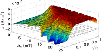
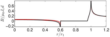
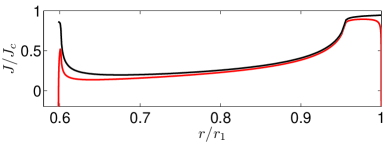
The parameter determines the reduction of the total ring current as a result of a perforation. This is analogous to the relative change in flux in the simplified model described in section IV. We artificially inject this current at a predetermined applied field, and subsequently let the simulation proceed normally, i.e. according to equation 7 again. Figure 4 shows field and current profiles just before and shortly after a perforation. We observe that most of the current change occurs near the inner edge. In the Meissner region there is some noticeable reduction in the current closer to the inner flux front, but towards the outer flux front there is hardly any change at all. Near the outer edge, though, the current has decreased considerably. These features compare favourably with the experimental current profiles shown in figures 1 and 3.
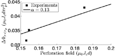
In figure 5 we show computed values of the flux jumps size versus the perforation field for different values of the blocking parameter . Also included in the plot is the first jump in some experiments. The plot shows that the total ring current is reduced by approximately 13 % by perforations. This is considerably smaller than the reduction we would infer from the plots of in figure 2 using , where the relative change in the flux is for the first jumps. This is of course due to the fact that most of the current change occurs near the inner edge where the effect on the flux in the central hole is greatest. The value also is more in line with the plot of total current in figure 3, which shows a relative change in current of for the first jump.
VI Conclusion
We have proposed a method to estimate the temperature rise during dendritic avalanches in superconducting thin films. This is accomplished using MO imaging to measure the flux change in the central hole of a superconducting MgB2 ring caused by avalanches stretching from the outer to the inner edges of the ring. Our model assumes that the dendrite tip creates a short-lived, resistive heated channel as it crosses the ring, injecting flux into the central hole. From this model we are able to estimate the peak temperature during flux injection to be K, the duration of process to be s, and calculate the current profiles before and after injection events.
Acknowledgements.
We thank Paul Leiderer for doing ultrafast MO imaging on MgB2 samples following our request. ÅAFO, DS and THJ greatfully acknowledge the financial support from FUNMAT@UiO and the Research Council of Norway.Appendix A Stability of the numerical calculations
The stability of the numerical calculations described in section V hinges on a careful selection of finite replacement elements for the diverging diagonal terms in the kernel, equation (8). The problem has been dealt with in various ways previously Brandt and Clem (2004); Brandt (1998); Gilchrist and Brandt (1996); Brandt (1994). One way to obtain diagonal elements that work is the following: With an appropriate grid and corresponding weights one can integrate numerically over the ring width:
| (12) |
The right hand side can be split into diagonal and off-diagonal terms, and the equation can be rewritten as
| (13) |
The integral of over can be carried out by changing the order of integration of and . The -integration can be done analytically; the result is a smooth integrand for the integration except for a singularity at , but the integral is well defined over the entire interval . Equation (8) can be used to compute the off-diagonal elements on the right hand side, and the resulting set of diagonal elements give stable and accurate computations.
An additional numerical challenge comes from the fact that obtained from equation (10) diverges at the edges. One way to cope with this for a regular Bean model (no field dependent ) is to modify the law so that for current above there is an ohmic resistivity , in mathematical form that
With this small modification the supercritical currents quickly relax in the simulations.
The resistivity does not necessarily have a physical meaning in this context since its main purpose is to stabilise the simulation when the current reaches extremely large values. Still, such an ohmic resistivity is realistic in superconductors for currents larger than the critical current, and the use of the modified law is reasonable also from a physical point of view. We use a s-1. The value will in reality depend on magnetic field since it captures the motion of vortices - the more vortices moving will generate a larger electric field acting against the current. However, for the computations the exact value is not crucial provided it is small.
References
- Leiderer et al. (1993) P. Leiderer, J. Boneberg, P. Brüll, V. Bujok, and S. Herminghaus, Physical Review Letters 71, 2646 (1993).
- Bujok et al. (1993) V. Bujok, P. Brüll, J. Boneberg, S. Herminghaus, and P. Leiderer, Applied Physics Letters 63, 412 (1993).
- Durán et al. (1995) C. A. Durán, P. L. Gammel, R. E. Miller, and D. J. Bishop, Physical Review B 52, 75 (1995).
- Rudnev et al. (2003) I. A. Rudnev, S. V. Antonenko, D. V. Shantsev, T. H. Johansen, and A. E. Primenko, Cryogenics 43, 663 (2003).
- Welling et al. (2004) M. S. Welling, R. J. Westerwaal, W. Lohstroh, and R. J. Wijngaarden, Physica C: Superconductivity 411, 11 (2004), URL http://www.sciencedirect.com/science/article/B6TVJ-4D04XV8-1/%2/cf66ef0057569747e387c921d2c7f435.
- Wimbush et al. (2004) S. C. Wimbush, B. Holzapfel, and C. Jooss, Journal of Applied Physics 96, 3589 (2004).
- Rudnev et al. (2005) I. A. Rudnev, D. V. Shantsev, T. H. Johansen, and A. E. Primenko, Applied Physics Letters 87, 042502 (2005).
- Menghini et al. (2005) M. Menghini, R. J. Wijngaarden, A. V. Silhanek, S. Raedts, and V. V. Moshchalkov, Physical Review B 71, 104506 (2005).
- Johansen et al. (2001) T. H. Johansen, M. Baziljevich, D. V. Shantsev, P. E. Goa, Y. M. Galperin, W. N. Kang, H. J. Kim, E. M. Choi, M.-S. Kim, and S. I. Lee, Superconductor Science and Technology 14, 726 (2001).
- Zhao et al. (2002) Z. W. Zhao, S. L. Li, Y. M. Ni, H. P. Yang, Z. Y. Liu, H. H. Wen, W. N. Kang, H. J. Kim, E. M. Choi, and S. I. Lee, Phys. Rev. B 65, 064512 (2002).
- Swartz and Bean (1968) P. S. Swartz and C. P. Bean, Journal of Applied Physics 39, 4991 (1968).
- Mints and Rakhmanov (1981) R. G. Mints and A. L. Rakhmanov, RMP 53, 551 (1981).
- Mints and Brandt (1996) R. G. Mints and E. H. Brandt, Phys. Rev. B 54, 12421 (1996).
- Aranson et al. (2005) I. S. Aranson, A. Gurevich, M. S. Welling, R. J. Wijngaarden, V. K. Vlasko-Vlasov, V. M. Vinokur, and U. Help, Physical Review Letters 94, 037002 (2005).
- Denisov et al. (2006a) D. V. Denisov, A. L. Rakhmanov, D. V. Shantsev, Y. M. Galperin, and T. H. Johansen, Physical Review B 73, 014512 (2006a).
- Denisov et al. (2006b) D. V. Denisov, D. V. Shantsev, Y. M. Galperin, E.-M. Choi, H.-S. Lee, S.-I. Lee, A. V. Bobyl, P. E. Goa, A. A. F. Olsen, and T. H. Johansen, Physical Review Letters 97, 077002 (pages 4) (2006b), URL http://link.aps.org/abstract/PRL/v97/e077002.
- Kang et al. (2001) W. N. Kang, H.-J. Kim, E.-M. Choi, C. U. Jung, and S.-I. Lee, Science 292, 1521 (2001).
- Choi et al. (2005) E. M. Choi, H. S. Lee, H. J. Kim, B. Kang, S. I. Lee, A. A. F. Olsen, D. V. Shantsev, and T. H. Johansen, Applied Physics Letters 87, 152501 (2005).
- Baziljevich et al. (2002) M. Baziljevich, A. V. Bobyl, D. V. Shantsev, E. Altshuler, T. H. Johansen, and S. I. Lee, Physica C 369, 93 (2002).
- Jooss et al. (2002) C. Jooss, J. Albrecht, H. Kuhn, H. Kronmüller, and S. Leonhardt, Reports on Progress in Physics 65, 651 (2002).
- Olsen et al. (2006) Å. A. F. Olsen, T. H. Johansen, D. Shantsev, E.-M. Choi, H.-S. Lee, H. J. Kim, and S.-I. Lee, Physical Review B (Condensed Matter and Materials Physics) 74, 064506 (pages 6) (2006), URL http://link.aps.org/abstract/PRB/v74/e064506.
- Roth et al. (1989) B. J. Roth, N. G. Sepulveda, and J. John P. Wikswo, Journal of Applied Physics 65, 361 (1989), URL http://link.aip.org/link/?JAP/65/361/1.
- Eom et al. (2001) C. B. Eom, M. K. Lee, J. H. Choi, L. J. Belenky, X. Song, L. D. Cooley, M. T. Naus, S. Patnaik, J. Jiang, M. Rikel, et al., Nature 411, 558 (2001).
- Kim et al. (2001) H.-J. Kim, W. N. Kang, E.-M. Choi, M.-S. Kim, K. H. P. Kim, , and S.-I. Lee, Physical Review Letters 87, 087002 (2001).
- Barkov et al. (2003) F. L. Barkov, D. V. Shantsev, T. H. Johansen, P. E. Goa, W. N. Kang, H. J. Kim, E. M. Choi, and S. I. Lee, Physical Review B 67, 064513 (2003).
- Brojeny and Clem (2003) A. A. B. Brojeny and J. R. Clem, Physical Review B (Condensed Matter and Materials Physics) 68, 174514 (pages 9) (2003), URL http://link.aps.org/abstract/PRB/v68/e174514.
- Brandt (2005) E. H. Brandt, Physical Review B (Condensed Matter and Materials Physics) 72, 024529 (pages 12) (2005), URL http://link.aps.org/abstract/PRB/v72/e024529.
- Norris (1970) W. T. Norris, Journal of Physics D: Applied Physics 3, 489 (1970), URL http://stacks.iop.org/0022-3727/3/489.
- Zeldov et al. (1994) E. Zeldov, J. R. Clem, M. McElfresh, and M. Darwin, Physical Review B 49, 9802 (1994).
- Brandt and Indenbom (1993) E. H. Brandt and M. Indenbom, Phys. Rev. B 48, 12893 (1993).
- Brandt (1994) E. H. Brandt, Phys. Rev. B 50, 4034 (1994).
- Brandt (1996) E. H. Brandt, Phys. Rev. B 54, 4246 (1996).
- Brandt (1997) E. H. Brandt, Physical Review B 55, 14513 (1997).
- Brandt (1998) E. H. Brandt, Phys. Rev. B 58, 6506 (1998).
- Brandt and Clem (2004) E. H. Brandt and J. R. Clem, Physical Review B (Condensed Matter and Materials Physics) 69, 184509 (pages 12) (2004), URL http://link.aps.org/abstract/PRB/v69/e184509.
- Gilchrist and Brandt (1996) J. Gilchrist and E. H. Brandt, Phys. Rev. B 54, 3530 (1996).