Proceedings of CK2005, International Workshop on Computational Kinematics
Cassino May 4-6, 2005
paper xxCK2005
STRATEGIES FOR THE DESIGN
OF A SLIDE-O-CAM TRANSMISSION
Abstract
The optimization of the pressure angle in a cam-follower transmission is reported in this paper. This transmission is based on Slide-o-Cam, a cam mechanism with multiple rollers mounted on a common translating follower. The design of Slide-o-Cam, a transmission intended to produce a sliding motion from a turning drive, or vice versa, was reported elsewhere. This transmission provides pure-rolling motion, thereby reducing the friction of rack-and-pinions and linear drives. The pressure angle is a suitable performance index for this transmission because it determines the amount of force transmitted to the load vs. that transmitted to the machine frame. Two alternative design strategies are studied, namely, () increase the number of lobes on each cam or () increase the number of cams. This device is intended to replace the current ball-screws in Orthoglide, a three-DOF parallel robot for the production of translational motions, currently under development at Ecole Centrale de Nantes for machining applications.
1 Introduction
In robotics and mechatronics applications, whereby motion is controlled using a piece of software, the conversion of motion from rotational to translational is usually done by either ball screws or linear actuators. Of these alternatives, ball screws are gaining popularity, one of their drawbacks being the high number of moving parts that they comprise, for their functioning relies on a number of balls rolling on grooves machined on a shaft; one more drawback of ball screws is their low load-carrying capacity, stemming from the punctual form of contact by means of which loads are transmitted. Linear bearings solve these drawbacks to some extent, for they can be fabricated with roller bearings; however, these devices rely on a form of direct-drive motor, which makes them expensive to produce and to maintain.
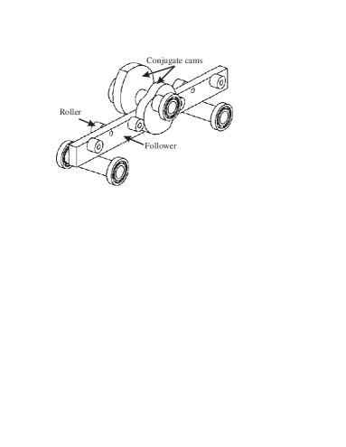
A novel transmission, called Slide-o-Cam, was introduced in [1] as depicted in Fig. 2, to transform a rotation into a translation. Slide-o-Cam is composed of four major elements: () the frame, () the cam, () the follower and () the rollers. The input axis on which the cam is mounted, the camshaft, is driven at a time-varying angular velocity, by an actuator under computer-control. Power is transmitted to the output, the translating follower, which is the roller-carrying slider, by means of pure-rolling contact between cam and roller. The roller, in turn, comprises two components, the pin and the bearing. The bearing is mounted at one end of the pin, while the other end is press-fit into the roller-carrying slider. Contact between cam and roller thus takes place at the outer surface of the bearing. The mechanism uses two conjugate cam-follower pairs, which alternately take over the motion transmission to ensure a positive action; the rollers are thus driven by the cams throughout a complete cycle. The main advantage of using a cam-follower mechanism instead of an alternative transmission to transform rotation into translation is that contact through a roller reduces friction, contact stress and wear.
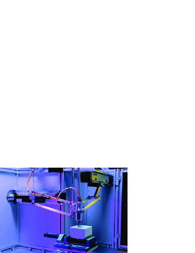
This transmission, once fully optimized, will replace the three ball screws used by the Orthoglide prototype [2]. Orthoglide features three prismatic joints mounted orthogonaly, three identical legs and a mobile platform, which moves in Cartesian space with fixed orientation, as shown in Fig. 2. The three motors are SANYO DENKI (ref. P30B08075D) with a constant torque of 1.2 Nm from 0 to 3000 rpm. This property enables the mechanism to move throughout the workspace a 4-kg load with an acceleration of 17 ms-2 and a velocity of 1.3 ms-1. Furthermore, the pitch is 50 mm per cam turn, while the minimum radius of the camshaft is 8.5 mm. A new arrangement of camshaft, rollers and follower is proposed to reduce the inertial load when more than two cams are needed.
Unlike Lampinen [3], who used a genetic algorithm, or Zhang and Shin [4], who used what they called “the relative-motion method,” where the relative velocity and acceleration of the the follower with respect to the cam is prescribed, we use a deterministic method that takes into account geometric and machining constraints [5].
The pressure angle (or its complement, the transmission angle) is a key performance index of cam-follower transmissions. One definition of pressure angle is the acute angle between the direction of the output force and the direction of the velocity of the point where the output force is applied [6].
Moreover, unlike Carra, Garziera and Pellegrini [7], who used a negative radius-follower to reduce the pressure angle, we use a positive radius-follower that permits us to assemble several followers on the same roller-carrier. To optimize the pressure angle, two alternative design strategies are studied, namely, () increase the number of lobes on each cam or () increase the number of cams. The relations defined in [8] for cam profiles with one lobe are extended to several lobes.
2 Synthesis of the Planar Cam Mechanism
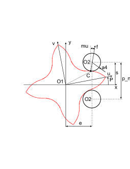
Let the - frame be fixed to the machine frame and the - frame be attached to the cam, as depicted in Fig. 4. is the origin of both frames, while is the center of the roller, and is the contact point between cam and roller. The geometric parameters defining the cam mechanism, with lobes, are illustrated in the same figure. The notation of this figure is based on the general notation introduced in [9] and complemented in [8], namely,
-
•
, the pitch, i.e., the distance between the center of two rollers on the same side of the follower, in single-lobed cams (distance is in -lobbed cams);
-
•
, the number of lobes;
-
•
, the distance between the axis of the cam and the line of centers of the rollers;
-
•
, the radius of the roller bearing, i.e., the radius of the roller;
-
•
, the angle of rotation of the cam, the input of the mechanism;
-
•
, the displacement of the follower, given by the the position of the center of the roller, namely, the output function of the mechanism;
-
•
, the pressure angle;
-
•
, the force transmitted from cam to roller.
In our design, is set to 50 mm, in order to meet the Orthoglide specifications.
2.1 The Input-Output Function
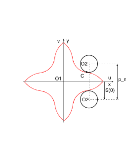
The above parameters as well as the contact surface on the cam are determined by the geometric relations dictated by the Aronhold-Kennedy Theorem in the plane [10]. When the cam makes a complete turn (), the displacement of the roller is equal to , i.e., the distance between rollers on the same side of the roller-carrying slider (). Furthermore, if we consider the home configuration of the roller, as depicted in Fig. 4, the roller is below the -axis for , so that we have . Hence, the expression for the input-output function is
| (1) |
The expressions for the first and second derivatives of with respect to will be needed; these are readily derived, namely,
| (2) |
2.2 Cam-Profile Determination
The cam profile is determined by the displacement of the contact point around the cam. This contact between one lobe and one roller takes place within . For this domain we find the profile of one lobe. The remaining lobes are found by rotation around . The Cartesian coordinates of in the - frame take the form [9]
with coefficients , and given by
| (3a) | |||||
| (3b) | |||||
| (3c) | |||||
where is the directed angle between the axis of the cam and the translating direction of the follower; is positive in the ccw direction. Considering the sign-convention adopted for the input angle and for the output , as depicted in Fig. 4, we have
| (4) |
We introduce now the non-dimensional design parameter , which will be extensively used:
| (5) |
Thus, from Eqs.(1), (2a), (3a–c), (4) and (5), we derive the expressions for coefficients , and :
| (6a) | |||||
| (6b) | |||||
| (6c) | |||||
whence a first constraint on , , is derived. With such a definition, however, the cam profile does not close.
An extended angle is introduced [11], so that the cam profile closes. Angle is obtained as the root of the equation . In the case of Slide-o-Cam, is negative, as shown in Fig. 5 for a cam with one lob. The contact between the cam profile and one roller is made (resp. is lost) for or as depicted in Fig. 5 (c&d).
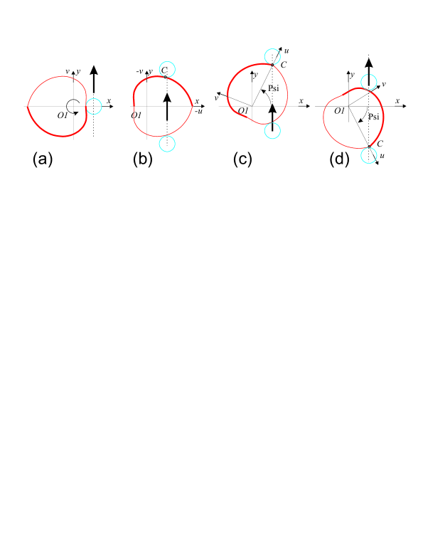
Consequently, the cam profile closes within , with a corresponding relation for the remaining lobes.
2.3 Pitch-curve Determination
The pitch curve is the trajectory of the center of the roller, distinct from the trajectory of the contact point , which produces the cam profile. The Cartesian coordinates of points in the - frame are , as depicted in Fig. 4. Hence, the Cartesian coordinates of the pitch curve in the - frame are
| (7a) | |||||
| (7b) | |||||
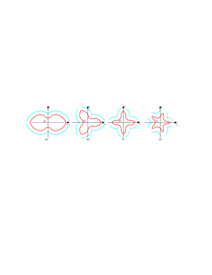
Figure 6 shows a plot of the cam profile and its pitch curve, within , throughout all lobes.
2.4 Geometric Constraints on the Mechanism
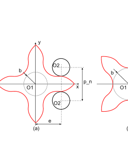
In order to lead to a feasible mechanism, the radius of the roller must satisfy two conditions, as shown in Fig. 7:
-
•
Two consecutive rollers on the same side of the roller-carrying slider must not interfere with each other. Since is the distance between the center of two consecutive rollers, we have the constraint . Hence the first condition on :
(8) -
•
The radius of the shaft on which the cams are mounted must be taken into consideration. Hence, we have the constraint , the second constraint on in terms of the parameter thus being111 It is possible to have if the cams and the shaft are machined from the same block. Thus, there is a common point, referred to as in Fig. 7b, between the shaft and the cam profile. This will not be the solution chosen for our design, because it is too complicated to machine the cams and the shaft on the same block.
(9)
Considering the initial configuration of the roller, as depicted in Fig. 4, the -component of the Cartesian coordinate of the contact point is negative in this configuration, i.e., . However, from the expression for and for parameters and given in Eqs. (6b & c), respectively, the above relation leads to the condition:
| (10) |
Further, we define parameters and as
| (11) |
Now we derive a constraint . Since , we have
Hence,
Furthermore, from the constraint on established in Eq. (8), we have , whence . Consequently, the constraint leads to the constraint .
We transform now the expression for by using the trigonometric relation:
Hence, the constraint becomes
which holds only if . Finally, the constraint leads to a constraint on , namely222If in the initial configuration the roller were on the upper side of the -axis, the input-output function would be , and we would have the constraint , which would lead to the same constraint .,
| (12) |
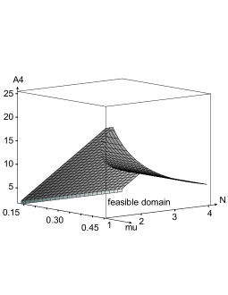
Equations 8, 9 and 12 permit us to reduce the design parameter space. Figure 8 depicts the design parameter space for and . We can notice that when the number of lobes by cam increases, the maximum value of decreases.
2.5 Pressure Angle
The pressure angle of cam-roller-follower mechanisms is defined as the angle between the common normal at the cam-roller contact point and the velocity of as a point of the follower [12], as depicted in Fig. 4, where the pressure angle is denoted by . This angle plays an important role in cam design. The smaller , the better the force transmission. In the case of high-speed operations, i.e., angular velocities of cams exceeding 50 rpm, the pressure-angle is recommended to lie within 30∘.
2.6 Conjugate Cams
To reduce the pressure angle, several cams can be assembled in the same cam-shaft. We note the number of cams and the angle of rotation between two adjacent cams, i.e.,
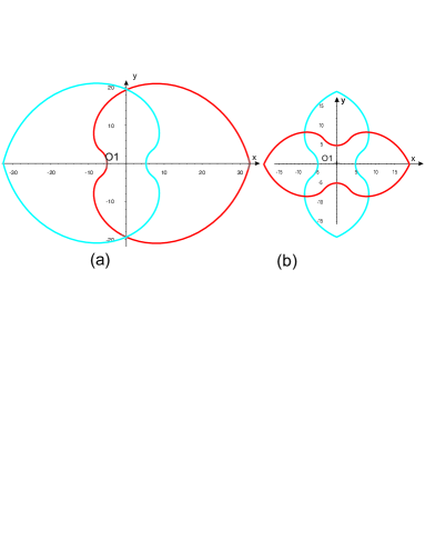
On the Slide-o-Cam mechanism first designed in [1], two conjugate cams with one lobe each and were used. Figure 9 shows two cam profiles with one and two lobes.
2.7 Convexity of the Cam Profile
The convexity of the cam influences the accuracy of the machining; for this reason it is preferable to have a convex cam profile for each part of the cam where it drives the roller. In this section, we establish conditions on the design parameters and in order to have such a property. We will thus study the sign of the curvature of the cam profile via that of the pitch curve.
The curvature of any planar parametric curve, in terms of the Cartesian coordinates and , and parameterized with any parameter , is given in [12],
| (13) |
The sign of in Eq.(13) tells whether the curve is convex or concave at a point: a positive implies a convexity, while a negative implies a concavity at that point. The computation of the first and second derivatives of the Cartesian coordinates of the pitch curve, defined in Eqs. (7), with respect to the angle of rotation of the cam, , are
| (14a) | |||||
| (14b) | |||||
| (14c) | |||||
| (14d) | |||||
By substituting , with Eqs.(14a-d) into Eq.(13), the curvature of the pitch curve can be obtained as
| (15) |
provided that the denominator never vanishes for any value of , i.e., if we observe the condition:
Considering the expression for in Eq.(15), we have, for every value of ,
whence the condition on :
| (16) |
The condition on given in Eq.(16) must be combined with the condition established in Eq.(12), . Hence, the final convexity condition of the pitch curve is:
| (17) |
3 Influence of the Number of Conjugate Cams and the Number of Lobes on the Pressure Angle
3.1 Active Angular Interval of the Pressure Angle
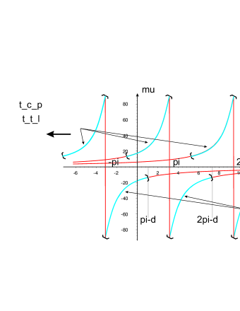
We are only interested in the interval of where the cam drives the roller to go to the right; we call this the active interval. An other interval of exists, with the same range, when the cam drives the roller to go to the left as is depicted in Fig. 10.
-
•
A single-cam mechanism: The active interval is:
Indeed, if we start the motion in the home configuration depicted in Fig. 4, with the cam rotating in the ccw direction, the cam begins to drive the roller only when ; the cam can drive the follower until contact is lost, i.e., when , as shown in Fig. 5c. With only one cam, the cam cannot drive the roller throughout one complete turn, as depicted in Fig. 10. This result holds for all values of . Thus, a cam-follower assembly must have a least two conjugate cams. When , contact between two followers and the cam occurs.
-
•
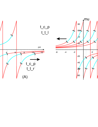
A two-conjugate-cam mechanism: The active interval is:
Indeed, the conjugate cam can also drive the follower when ; there is, therefore, a common interval, for , during which two cams can drive the follower. In this interval, the conjugate cam can drive a roller with lower absolute values of the pressure angle. We assume that, when the two cams drive the rollers, the cam with the lower absolute value of pressure angle effectively drives the follower. Consequently, we are only interested in the value of the pressure angle in the interval , as depicted in Fig. 11.
-
•
A three-conjugate-cam mechanism: For the same reason, the active interval is:
This interval is 33% smaller than a two-conjuage-cam-mechanism, the part of the interval removed having the highest pressure angle, as depicted in Fig. 12.
3.2 Pressure Angle and Design Parameters
We study here the influence of design parameters , and on the values of the pressure angle, whith the cam driving the roller, as reported in [13]. We also study the influence of the number of conjugate cams on the value of pressure angle.
-
•
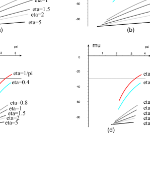
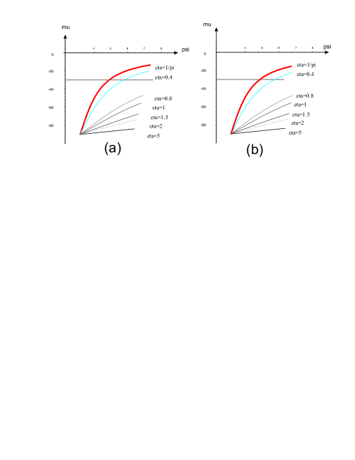
Influence of parameter
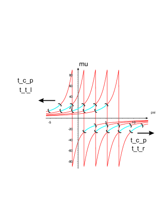
Figure 13 shows the influence of the parameter on the pressure angle, with and being fixed for several numbers of cams and lobes. From these plots we have the result:
The lower , the lower the absolute value of the pressure angle, with , as defined in Eq.17.
This result is the same if we consider a single cam with several lobes or a two- or three-conjugate-cam mechanism.
-
•
Influence of the radius of the roller
Parameter does not appear in the expression for the pressure angle, but it influences the value of the extended angle , and hence the plot boundaries of the pressure angle, as shown in Fig. 14 for two value of .
By computing the value of the extended angle for several values of , we notice that the higher , the lower the absolute value of . Consequently, since the boundaries to plot the pressure angle for a system with two conjugate cams are and or and for three conjugate cams, we notice that when we increase , decreases or, equivalently, increases and the boundaries are translated toward the left, i.e., toward higher absolute values of the pressure angle. We thus have the result:
The lower , the lower the absolute value of the pressure angle.
This result is valid for single or conjugate-cam mechanisms and is independent of the number of lobes.
-
•
Influence of the number of lobes
By computing the value of the pressure angle for several values of , as depicted in Fig. 13, we have the result:
The lower , the lower the absolute value of the pressure angle.
For at least two lobes, contact is lost when the pressure angle is greater than .
-
•
Influence of the Number of Conjugate Cams
Figures 11(a) and 12 show that the higher the number of cams, the lower the active interval. Especially, the number of cams reduces the maximum absolute value of the pressure angle. Therefore,
The higher the number of conjugate cams, the lower the absolute value of the pressure angle.
4 Conclusions
Two design strategies have been used in this paper to reduce the pressure angle in the Slide-o-Cam mechanism. The optimum solution is found whenever () the number of lobes is one, () for the higher number of conjugate cams, () for the smallest value of the radius of the roller and () for the smallest value of . However, to minimize the deformation of the roller pin, have to be computed to resist to efforts during the motion as is made in [8]. Further research is currently underway to evaluate the influence of variations in the design parameters on the pressure angle and the active interval and the design of cam with non-convex shape.
References
- [1] González-Palacios, M.A. and Angeles, J., 2003, The design of a novel pure-rolling transmission to convert rotational into translational motion”, Journal of Mechanical Design, Vol. 125, pp. 205–207
- [2] Chablat, D. and Wenger Ph., 2003, “Architecture Optimization of a 3-DOF Parallel Mechanism for Machining Applications, the Orthoglide,” IEEE Transactions on Robotics and Automation, Vol. 19/3, pp. 403–410, June.
- [3] Lampinen, J. 2003, “Cam shape optimisation by genetic algorithm,” Computer-Aided Design, Vol. 35, pp. 727 -737.
- [4] Zhang, Y. and Shin, J.-H., 2004, “A Computational Approach to Profile Generation of Planar Cam Mechanisms,” Journal of Mechanical Design, Vol. 126-1, pp. 183–188.
- [5] Bouzakis, K.D., Mitsi, S. and Tsiafis, J., 1997, “Computer-Aided Optimum Design and NC Milling of Planar Cam Mechanims,” Int. J. Math. Tools Manufact. Vol. 37, No. 8, pp. 1131–1142.
- [6] Shigley, J.E., Uicker, J.J., 1980, “Theory of Machines and Mechanisms,” McGraw-Hill, New York, 1980.
- [7] Carra, S., Garziera, R. and Pellegrini, M., 2004, “Synthesis of cams with negative radius follower and evaluation of the pressure angles,” Mechanism and Machine Theory, Vol. 34, pp. 1017–1032.
- [8] Renotte J., Chablat D. and Angeles J., 2004, “The Design of a Novel Prismatic Drive for a Three-DOF Parallel-Kinematics Machine,” ASME Design Engineering Technical Conferences, September-October 28-2, Salt Lake City, Utah, USA.
- [9] González-Palacios, M. A. and Angeles, J., 1993, Cam Synthesis, Kluwer Academic Publishers B.V., Dordrecht.
- [10] Waldron, K. J. and Kinzel, G. L., 1999, Kinematics, Dynamics, and Design of Machinery, John Wiley & Sons, Inc., New York.
- [11] Lee, M.K., 2001, Design for Manufacturability of Speed-Reduction Cam Mechanisms, M.Eng. Thesis, Dept. of Mechanical Engineering, McGill University, Montreal.
- [12] Angeles, J. and López-Cajún,C., 1991, Optimization of Cam Mechanisms, Kluwer Academic Publishers B.V., Dordrecht.
- [13] Zhang W. and Angeles, J. 2004, “A parametric study of planar cam-roller speed reducers,” Transactions of the Canadian Society for Mechanical Engineering, Vol. 28, No. 2A, pp. 263–275.