Dynamics of a domain wall in a magnetic nanostrip: a toy model
Abstract
In this report we demonstrate a simple model for the motion of a vortex domain wall in a ferromagnetic strip of submicron width under the influence of an external magnetic field. The model exhibits three distinct dynamical regimes. In a viscous regime at low fields the wall moves rigidly with a velocity proportional to the field. Above a critical field the motion becomes underdamped as the vortex moves periodically across the strip; these oscillations are accompanied by a slow drift with a decreasing velocity. At still higher fields the drift velocity starts rising linearly with the field again but with a much lower mobility than in the low-field regime. We calculate the relevant quantities and compare them to experimentally observed values.
I Introduction
Dynamics of domain walls in ferromagnetic strips and rings with submicron dimensions is a subject of active research.Allwood et al. (2005); Thomas et al. (2007); Chien et al. (June 2007) This topic is directly relevant to several proposed schemes of magnetic memory and is also interesting from the standpoint of basic physics. The dynamics of domain walls under an applied magnetic field has distinct regimes: viscous motion with a relatively high mobility at low fields and underdamped oscillations with a slow drift at higher fields.Beach et al. (2005)
The nontrivial dynamics is related to the composite nature of a domain wall in a nanostrip: it consists of a few—typically two or three—elementary topological defects in the bulk and at the edge of the strip. As a result, a domain wall has several low-energy degrees of freedom that are relevant to the dynamics. Weak external perturbations engage only the softest (zero) mode—rigid translations along the strip. Larger external forces excite higher modes thereby altering the character of motion.
The general approach to the dynamics of domain walls in thin ferromagnetic strips with a submicron width and thickness was described recently by Tretiakov et al.Tretiakov et al. (unpublished) The configuration of a domain wall is parametrized by a few collective coordinates and the free energy of the system is treated as a function of . The resulting equations of motion can be written in the vector notation as
| (1) |
Here components of the vector are generalized forces ; the symmetric matrix and antisymmetric matrix represent the viscous and gyrotropic tensors, respectively.
The main goal of this paper is to illustrate the collective-coordinate approach on a very simple model of a vortex domain wallChern (unpublished) that served as a prototype for a more realistic model of Youk et al.Youk et al. (2005) Despite its simplicity, the model captures all of the main features of a vortex domain wall and yields simple analytical results for the relevant physical quantities. Quantitatively speaking, the values of the forces computed in this model deviate by no more than 30% from those obtained in the more realistic model of the vortex wall. Thus one can make meaningful comparisons between the analytical results obtained in this paper and experimental data.
In the main body of the paper we describe the simplified model of the wall and compute the generalized forces and the viscous and gyrotropic tensors. By substituting these quantities into Eq. (1) we obtain simple equations of motion. At low fields the equations describe steady viscous motion of the wall with a velocity proportional to the applied field. The vortex is shifted in the transverse direction by an amount proportional to the velocity of the wall. At a critical velocity the vortex is expelled from the strip and the steady motion breaks down giving way to an oscillatory regime. As the applied field increases further, the drift velocity decreases at first but then again becomes proportional to the applied field; the mobility coefficient is substantially lower than the corresponding value in the viscous regime at low fields. These results are compared to experimental data.
II model wall
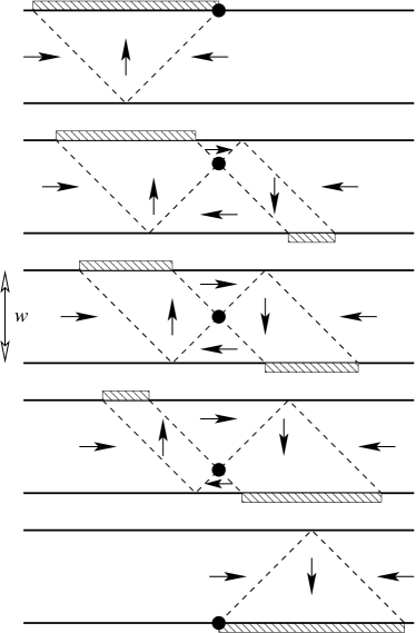
In our calculations of the wall dynamics, we use a simple model of the vortex domain wall consisting of four domains with uniform magnetization and separated by Neel walls (Fig. 1).
We assume that only two softest modes of the vortex wall are involved in magnetization dynamics, so that the configuration of the wall is fully described by the two coordinates of the vortex core. In that case the equations of motion (1) reflect the balance of forces acting on a particle moving in two dimensions with a velocity . The forces include a conservative term , a viscous term , and a gyrotropic termThiele (1973) . The gyrotropic force depends on the out-of-plane polarization of the vortex core and the gyrotropic constant , where is the density of angular momentum.Tretiakov et al. (unpublished) The conservative and viscous terms are discussed next.
II.1 Free energy and conservative forces
In strips that support vortex domain walls, the dominant contribution to the energy in the absence of an applied field is due to magnetostatic interactions. For any domain wall in a strip of width , thickness , and saturation magnetization , there is a total magnetic charge associated with the wall.Youk et al. (2005) In a vortex wall, nearly all of this charge is expelled to the edge. In our simple model, magnetic charges form two lines of lengths and with constant density of charge per unit length .
The magnetostatic energy of this wall has a minimum at . This leads to a force that acts to keep the vortex centered on the strip. In general, the total exchange energy of the wall may change with the position of the vortex, altering the restoring force slightly. However, in our simplified model, the exchange cost comes entirely from the four Neel walls that make up the vortex wall. Because the length of these walls does not change as the vortex moves, we need not consider the exchange interaction in our analysis of the wall dynamics.
A line of charges of length has the self-energy
| (2) |
The divergence at requires a regularization. In a crude way this can be done by introducing a short-range cutoff in the integral, i.e. by integrating over distances , where is a numerical constant. We then obtain a logarithmic dependence on :
| (3) |
The self-energies of the two lines of charge is
| (4) | |||||
Note that the cutoff affects only the constant term ; the quadratic term is not sensitive to the exact value of .
In a similar way we evaluate the interaction of the two lines of charges,
| (5) | |||||
The sum of the quadratic terms in Eqs. (4) and (5) yields the “spring” energy , from which we determine the spring constant:
| (6) |
Next we deal with the Zeeman energy of the wall in the presence of an applied magnetic field parallel to the axis of the strip. A longitudinal shift of the vortex by results in a pure translation of the wall. Independently of the wall shape, the rigid shift changes the Zeeman energy by , where is the magnetic charge of the wall. Therefore the longitudinal Zeeman force is in any model.
The Zeeman force also has a transverse component. As can be seen from Fig. 1, transverse motion of the vortex core changes the total magnetization of the strip and thus affects its Zeeman energy. As the vortex core crosses the strip from top to bottom (Fig. 1), the Zeeman energy decreases linearly by . Therefore the transverse component of the Zeeman force is .
The total free energy of a wall with the vortex core at is thus
| (7) |
II.2 Viscosity tensor and viscous drag
We next consider the viscosity of the vortex wall. The viscosity that appears in Eq. (1) is a symmetric matrix whose components are given by:Tretiakov et al. (unpublished)
| (8) |
where is the azimuthal angle characterizing magnetization.
An infinitesimal shift in the collective coordinates and affects magnetization in the vicinity of the Neel walls only. We begin by considering the contribution of a single Neel wall emanating from the vortex core at , . For such a wall, derivatives with respect to collective coordinates can be reduced to ordinary gradients: and . As a result, the tensor components are equal to each other, up to a sign:
Note that this represents, up to a trivial constant, the exchange energy of the Neel wall, which has been calculated, e.g., in Ref. Chern et al., 2005. We thus obtain viscosity coefficients for the Neel walls intersecting at the vortex core, where the exchange length nm in permalloy. Opposite signs of the off-diagonal component can be understood by noting that, as the vortex moves along , the two Neel walls shift along and creating equal and opposite viscous forces in the direction.
The two peripheral Neel walls have the functional form , so that their contributions are the same as that of the central Neel wall perpendicular to them. Adding the contributions of all four Neel walls yields a total
| (9) |
independently of the vortex position.
It is instructive to compute the ratio of the viscous and gyrotropic forces:
| (10) |
The small value of Gilbert’s damping in permalloy, , Freeman et al. (1998) leads to the dominance of the gyrotropic force in strips with submicron widths. The smallness of can be exploited to organize an expansion in powers of this small parameter.
III Wall dynamics
Equations of motion (1) for two generalized coordinates and read
| (11) |
where is a viscosity tensor, is the polarization of the vortex core, and is the antisymmetric tensor with .Tretiakov et al. (unpublished) The generalized forces are derived from the free energy (7). We thus arrive at the following equations of motion for the vortex core:
| (12) |
where the equilibrium position of the vortex is given by
| (13) |
where . It is worth noting that the magnitudes of the transverse displacement are slightly different for the two values of the vortex polarization . This effect can be traced to the lack of the reflection symmetry in a vortex wall, which leads to nonzero transverse components of the Zeeman force and the viscous force . As a result, trajectories of vortex cores with and are slightly different.
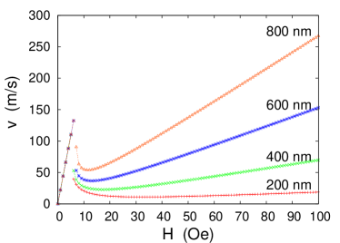
Analysis of the equations of motion yields three distinct regimes (Fig. 2). Below a critical field we find steady viscous motion with a high mobility . Immediately above the critical field the motion exhibits an oscillatory component; the drift velocity quickly decreases as the applied field grows. At much higher fields, , the drift velocity rises linearly again but with a much lower mobility than at low fields. The separation of scales and is guaranteed by the smallness of the parameter .
III.1 Low field:
In a low applied field the wall exhibits simple viscous motion. The transverse coordinate of the vortex will asymptotically approach its equilibrium position , so long as the latter is within the strip. The wall then moves rigidly with a steady longitudinal velocity
| (14) |
Experimental data of Beach et al. Beach et al. (2005) yield (m/s) at low fields for a strip 600 nm wide, which gives . while our Eq. (10) yields if we use the value of measured by Freeman et al. Freeman et al. (1998)
III.2 Critical field:
The low-field regime ends when the equilibrium position of the vortex core is pushed outside the strip edge, , making the steady state unreachable. As pointed out above, in permalloy strips with a width below 1 m the viscous force is small in comparison with the gyrotropic one. As a result, the equilibrium of a vortex in the transverse direction is set mostly by the balance of the transverse components of the gyrotropic force and the restoring force . The critical point is reached when :
| (15) |
With the aid of Eq. (6) we obtain the critical velocity
| (16) |
and the critical field
| (17) |
For permalloy, and . Van Waeyenberge et al. (2006) Taking the thickness of nm we obtain m/s. This is not too far from the critical velocity of 80 m/s observed by Beach et al.Beach et al. (2005)
Equation (16) shows that the critical velocity should grow linearly with the film thickness . It is easy to see that this result is valid beyond the crude model of a vortex wall adopted in this calculation. The two forces balancing each other (15) scale differently with . While the gyrotropic force is linear in , the restoring force comes from the magnetostatic energy, which represents Coulomb-like interaction of charges with density , hence (the dipolar part of) the restoring force is quadratic in . That gives .
III.3 High field: . General remarks
Numerical simulations indicate that, after the original vortex with a core polarization is expelled from the strip, a new vortex is injected at the same location with the opposite polarization . The vortex thus moves between the edges switching its core polarization each time it reaches an edge.
Once the transverse coordinate of the vortex becomes a dynamical variable, the motion acquires an entirely different character. As we already pointed out, the gyrotropic force dwarfs the viscous one, , in permalloy strips. To zeroth order in , the dynamics is conservative: the vortex core moves along equipotential lines . At this order, the wall would oscillate back and forth but would not move on average. Drift requires a nonzero viscosity: as the wall coordinate increases on average, the loss of Zeeman energy must be accounted for through viscous friction.
III.4 Very high field:
We first demonstrate that at a very high field the velocity is again proportional to the field and calculate the high-field mobility. The new field scale is set by the requirement that the restoring force be negligible in comparison with the Zeeman force . The characteristic field is
| (18) |
When , the dynamics is dominated by the Zeeman and gyrotropic forces, so that the vortex moves along an equipotential line , or .
As a result of the drift with a velocity , the Zeeman energy goes down on average at the rate . It is dissipated through heat generated at the rate
The transverse velocity of the vortex core reflects the balance between the longitudinal components of the gyrotropic and Zeeman forces: . We thus find the drift velocity
| (19) |
In the last transition we have used the relation between the coefficients of the viscosity tensor specific to this model (9).
III.5 High field: . Details
To find the drift velocity of the vortex at fields above the vortex expulsion field , we determine the total displacement of the vortex over a full cycle of motion from the top of the strip to the bottom and back again. The crossing time will be slightly different on the upward and downward trips due to the asymmetry of the vortex wall and the component of the Zeeman force.
Solving Eq. (11) with polarization gives us the crossing times and displacements and (top to bottom) and and (bottom to top):
| (21) |
The drift velocity is
The resulting curve is shown for several strip widths in Fig. 2. Note that the critical field is not exactly and actually changes slightly with the width. This is because the equilibrium points for both up- and downwardly polarized vortices must be expelled from the strip for the character of the motion to change. By Eq. (13) a downwardly polarized vortex requires a slightly higher field to expel than an upwardly polarized one. An expansion of Eq. (III.5) in powers of yields the high-field result (19).
IV Discussion
We have explored the dynamics of a vortex domain wall in a magnetic strip of a submicron width. We have applied the method of collective coordinatesTretiakov et al. (unpublished) to the case when the wall has two soft modes related to the motion of the vortex core. A simplified model of the vortex domain wall described in this paper yields solvable equations of motion. The calculated mobility of the wall in the steady-state viscous regime at low fields agrees well with the value measured by Beach et al.Beach et al. (2005) The steady motion breaks down when the equilibrium position of the vortex moves beyond the edge of the strip. The critical velocity (16) depends just on the magnetization length and the sample thickness; its calculated value agrees reasonably well with the data of Beach et al.Beach et al. (2005) The dynamics above the breakdown changes the character from overdamped to underdamped: the ratio of the viscous and gyrotropic forces acting on the wall in their experiment. In this regime the velocity sharply declines at first but later starts to rise again as the field strength increases. The high-field mobility is reduced in comparison with the low-field value by the factor ; the observed reduction is not as strong: .Beach et al. (2005)
In addition to simplifying the geometry (but not the topology) of the domain wall, we have made other assumptions that require further checking. First, we have assumed that any vortex absorbed by the edge is immediately reemitted. At fields lower than that required for emission to occur, the wall may simply stay transverse and continue to move in a viscous fashion. At higher fields, there may be short delays between absorption and reemission during which the motion of the wall is again viscous; the higher mobility of a transverse wall would tend to increase the drift velocity.
Second, just as the appearance of as a new degree of freedom completely changes the character of the wall dynamics above the critical field , at still higher fields additional modes of the wall may become important. The number and dynamical characteristics of soft modes may also change discontinuously as additional vortices or antivortices are created and annihilated in the bulk of the strip. We have observed the creation and subsequent annihilation of a vortex-antivortex pair near the original vortex of the wall. Like the process described by Van Waeyenberge et al.,Van Waeyenberge et al. (2006) the pair creation mediates the flipping of the polarization of the wall vortex and results in the reversal of the gyrotropic force. Thus the dynamics is similar to that described in this paper: the vortex moves back and forth, while the domain wall slowly drifts along the strip. A possible way to detect this new regime is to measure the frequency of longitudinal oscillations: because the vortex does not reach the edge, the frequency should be higher than expected when the vortex moves from edge to edge.Tretiakov et al. (unpublished) We shall describe the onset of this type of motion more fully in future work.
V Acknowledgments
We thank Ya. B. Bazaliy, G. S. D. Beach, and C. L. Chien for valuable discussions. This work was supported in part by the NSF Grant No. DMR-0520491.
References
- Allwood et al. (2005) D. A. Allwood, G. Xiong, C. C. Faulkner, D. Atkinson, D. Petit, and R. P. Cowburn, Science 309, 1688 (2005).
- Thomas et al. (2007) L. Thomas, M. Hayashi, X. Jiang, R. Moriya, C. Rettner, and S. Parkin, Science 315, 1553 (2007).
- Chien et al. (June 2007) C. L. Chien, F. Q. Zhu, and J. G. Zhu, Physics Today (June 2007).
- Beach et al. (2005) G. S. D. Beach, C. Nistor, C. Knutson, M. Tsoi, and J. L. Erskine, Nature Mat. 4, 741 (2005).
- Tretiakov et al. (unpublished) O. A. Tretiakov, Y. B. Bazaliy, and O. Tchernyshyov (unpublished), eprint arXiv:0705.4463.
- Chern (unpublished) G.-W. Chern (unpublished).
- Youk et al. (2005) H. Youk, G.-W. Chern, K. Merit, B. Oppenheimer, and O. Tchernyshyov, J. Appl. Phys. 99, 08B101 (2005).
- Thiele (1973) A. A. Thiele, Phys. Rev. Lett. 30, 230 (1973).
- Chern et al. (2005) G.-W. Chern, H. Youk, and O. Tchernyshyov, J. Appl. Phys. 99, 08Q505 (2005).
- Freeman et al. (1998) M. R. Freeman, W. K. Hiebert, and A. Stankiewicz, J. Appl. Phys. 83, 6217 (1998).
- Van Waeyenberge et al. (2006) B. Van Waeyenberge, A. Puzic, H. Stoll, K. W. Chou, T. Tyliszczak, R. Hertel, M. Fahnle, H. Brückl, K. Rott, G. Reiss, et al., Nature (London) 444, 461 (2006).