Slow light with integrated gain and large pulse delay
Abstract
We demonstrate slow and stored light in Rb vapor with a combination of desirable features: minimal loss and distortion of the pulse shape, and large fractional delay (). This behavior is enabled by: (i) a group index that can be controllably varied during light pulse propagation; and (ii) controllable gain integrated into the medium to compensate for pulse loss. Any medium with the above two characteristics should be able to realize similarly high-performance slow light.
pacs:
42.50.Gy, 42.25.Bs, 32.80.QkOptical buffers with controllable delay are key components for both photonic optical networks and quantum information processing systems. Requirements for such optical buffers are an adjustable delay time (i.e., group index) for input signal pulses over a wide range of bandwidths, minimal pulse distortion and loss tuckerJLT05 , and high compression of the input pulse for high data density inside the delay medium. Large pulse delay (“slow light”) is achievable in many media including gas vapors lukin03rmp ; boydPO ; bigelowScience03 ; okawachiOE06 ; howellPRA06 , cold atoms hau , doped crystals manson05 , photonic bandgap crystals mori07 , semiconductor heterostructures ku , microresonators totsuka07 , and optical fibers patnaik ; linJOSAB04 ; mok ; kaloshaPRA07 . In these systems the group index is controllable using a variety of techniques including the application of a strong optical control field, varying the density of coupled atoms, or the coupling of a microresonator to a waveguide. However, large delay-bandwidth products are very challenging to obtain because residual absorption of the input signal pulse typically increases exponentially with the length of the medium. Here, we demonstrate a technique that provides independent control of the signal pulse group velocity and amplitude, using (i) a temporally varying group index in coordination with (ii) integrated gain in the medium. This combination of features allows for large fractional pulse delay (delay-bandwidth product ) with minimal distortion and absorption of the output pulse. The technique is general: any system with the two key characteristics of controllable group index and integrated gain should be able to realize high-performance slow light. We note that excellent progress toward this goal has also been made recently with a distinct technique involving gap solitons in an optical fiber Bragg grating mok .
The steep dispersion necessary to create a large group index is usually achieved in a very narrow frequency band through a resonant transmission feature. The achievable pulse delay-bandwidth product is therefore limited () by pulse absorption in the frequency wings of the resonance since losses grow exponentially as a high-bandwidth pulse propagates through a high group-index (narrow transmission bandwidth) medium boydPRA05 . Increasing the bandwidth of the resonant medium typically reduces the group index proportionally, such that the delay-bandwidth product remains limited. However, a medium with integrated gain can compensate for absorption and allow large pulse delays to be obtained. Even in the presence of gain, the finite bandwidth of the resonance leads to pulse distortion. Nevertheless, as we show here, large pulse delays with minimal distortion and attenuation can be created through the combined use of integrated gain and dynamic control of the group index and hence the instantaneous group velocity inside the medium.
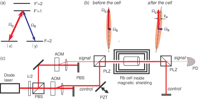
Our demonstration experiments employed a dynamic form of electromagnetically induced transparency (EIT) in warm Rb vapor lukin03rmp ; fleischhauer00 ; phillips ; mair ; fleischhauer02 . In EIT, a strong control field determines the propagation of a weak signal pulse interacting near resonance with an ensemble of radiators such as atoms, typically in a -scheme (see Fig. 1(a)). The group velocity of the signal is
| (1) |
where is the Rabi frequency induced by the control field on the relevant atomic transition, is the atomic number density, and is the coupling constant between the signal field and the atomic transition with the optical wavelength, the vacuum speed of light, and the optical decoherence rate. The group index, . In many EIT media, slow light () has been demonstrated lukin03rmp ; boydPO ; bigelowScience03 ; okawachiOE06 ; howellPRA06 ; manson05 . The group delay, , of a signal pulse in such an EIT medium (relative to propagation in vacuum) is given by
| (2) |
where is the length of the atomic medium and is the optical depth. The bandwidth of the EIT resonance, , for the propagating pulse through the dense atomic medium is
| (3) |
Residual signal-field absorption in an EIT medium, , is well-approximated by lukin03rmp
| (4) |
where is the ground-state decoherence rate of the atomic system.
Significant delay of a signal pulse while simultaneously preserving its amplitude and shape requires both small group velocity (hence small control field intensity) and large spectral bandwidth and low absorption (hence large control field intensity). These two competing conditions offset each other boydPRA05 , such that the delay-bandwidth product for EIT-based slow light () is independent of the control field intensity, , but proportional to the optical depth. Therefore, a larger delay-bandwidth product requires a larger optical depth, which comes at the expense of exponentially greater residual absorption (even for high-quality EIT). This increased absorption can be compensated for with integrated gain, but can still lead to pulse shape broadening and distortion due to fractionally larger absorption and nonlinear dispersion in the wings of the transmission resonance. As we show here, such pulse shape corruption can be corrected by increasing the control field intensity (i.e., decreasing the group index) as the signal pulse enters the EIT medium. With this technique, the leading edge of the pulse enters the medium with the control field at low intensity (i.e., small ); whereas the trailing edge enters the medium with a stronger control field (i.e., larger ). Thus, the trailing edge of the signal pulse has a smaller net delay inside the atomic medium than the leading edge, which compresses the temporal extent of the pulse. Tailored use of such compression allows a signal pulse to propagate through a medium with a lower mean group velocity (i.e., larger net delay) than would be possible with a constant control field while preserving the temporal pulse length and thus bandwidth. Related theoretical proposals for temporal pulse shape manipulation have recently been made for a variety of slow light media buffaPRA04 ; arkhipkinPRA06 ; kaloshaPRA07 .
The evolution of a signal pulse of amplitude as it propagates through an EIT medium can be described by a simple equation in the limit that and varies adiabatically fleischhauer02 . In this limit, the internal degrees of freedom of the atomic system can be evaluated perturbatively and then eliminated, leaving the following propagation equation for the signal pulse amplitude near EIT resonance:
| (5) | |||||
Here is the signal field gain associated with the medium (see discussion below), is the propagation direction through the medium, and the remaining parameters have been defined above. In the absence of gain () and with a constant control field (), Eq. (5) reverts to a simple wave equation for the signal field with a group velocity given by Eq. (1) and absorptive losses by Eq. (4). With appropriate ramping of and integrated gain in the medium (non-zero ), Eq. (5) qualitatively describes signal pulse propagation with large fractional delay and insignificant loss and distortion — consistent with the experimental demonstrations reported here.
In our experiments, we employed a degenerate -system based on ground-state Zeeman sublevels of 87Rb, with control and signal fields having orthogonal linear polarizations (see Fig. 1(a)). This operational configuration provides EIT with integrated gain for the signal field due to polarization self-rotation self-rot ; novikovaOL00 ; novikovaJMO02 . In this well-studied phenomenon, the major polarization axis of elliptically polarized light rotates during propagation (see Fig. 1(b)) due to a differential refractive index for the light’s two circularly-polarized components, induced by an ac-Stark shift of the atomic Zeeman sublevels arising from off-resonant excited states SRnote . For a simplified four-level system the angle of polarization self-rotation is novikovaJMO02 :
| (6) |
where is the effective detuning of the off-resonant excited state novikovaOL00 , is the ellipticity of the total optical field, and we define as the self-rotation coefficient. A linearly-polarized field (such as the control field or signal field alone) has zero ellipticity and thus suffers no rotation of its polarization. However, when the orthogonally polarized control and signal fields are both present, the total field is in general elliptically polarized depending on the phase difference, , between the control and signal fields. The resulting polarization self-rotation of the total field depends on the degree of ellipticity, . The rotation of the polarization ellipse serves to transfer a fraction of the control field intensity into the signal field, leading to integrated gain of the signal field, . Note, however, that this change in the signal field intensity does not affect the coherent properties of the medium; nor does it significantly decrease the control field intensity (since ). Thus by varying the polarization phase difference between the control and signal fields, we can controllably vary the intensity of the signal pulse significantly while having little effect on the dynamics of signal pulse propagation.
We used the experimental setup shown schematically in Fig. 1(c) to demonstrate this technique. An extended cavity diode laser was tuned to 795 nm at the transition of 87Rb. Orthogonally polarized control and signal beams were created by separating two polarizations on a polarizing beam-splitter (PBS), sending them through two separate phase-locked acousto-optical modulators (AOM), and then recombining the first-order beams on a high-quality polarizer (PLZ) with extinction ratio of . One of the mirrors was mounted on a piezo-ceramic drive (PZT) which allowed the relative phase between the control and signal fields to be adjusted by changing the path length for the control field. Maximum total laser power at the Rb vapor cell was mW, collimated into a -mm beam diameter. The 87Rb vapor cell was housed inside four layers of magnetic shielding and heated conductively by a blown-hot-air oven. Two different cylindrical vapor cells were used for the various measurements: each had length of 75 mm and diameter of 25 mm and was filled with isotopically enriched 87Rb; one cell had 22 Torr and the other 40 Torr of Ne buffer gas at room temperature. After the laser fields traversed the cell, the signal field was filtered from the control field using a high-quality polarizer (PLZ) and its intensity measured using a photodetector (PD).
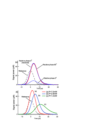
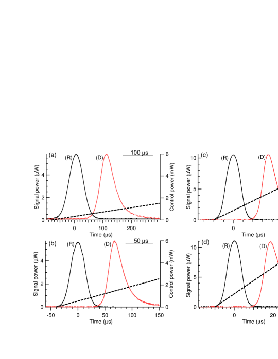
To optimize the signal-field gain, we adjusted the relative phase between the control and signal fields by varying the position of the mirror in the control-field channel using the PZT, as shown in Fig. 1(c). As expected, we found that changing the relative phase between the control and signal fields from to changes the amplitude of the signal pulse from its minimum (no self-rotation) to maximum, without affecting the output signal field pulse shape or delay (see Fig. 2(a)). We also found that the dependence of the delay of the amplified signal pulse on control field intensity follows Eq. (2), as shown in Fig. 2(b): i.e., the delay is inversely proportional to the control field intensity. These measurements confirm that polarization self-rotation acts as a form of integrated gain in the medium: it can increase the signal pulse amplitude and compensate for loss mechanisms, but does not affect the pulse delay or shape. Measured output signal pulses corresponding to weaker control fields in Fig. 2(b) are temporally broadened, consistent with Eq. 3. We next showed that such temporal broadening of the signal pulse due to finite EIT bandwidth can be eliminated by smoothly increasing the control field intensity (i.e., decreasing the group index) as the signal pulse enters and traverses the atomic medium. Changing the control field intensity, which is uniform across the length of the cell, creates a differential group delay for the front and the back of the pulse leading to pulse compression which compenates for broadening due to finite EIT bandwidth. Fig. 3 shows several measured examples of the combined use of linearly increasing control field intensity and polarization self-rotation, which allows signal pulse shape- and amplitude-preserving propagation with large fractional delay ( in the examples shown) for a wide range of pulse bandwidths.
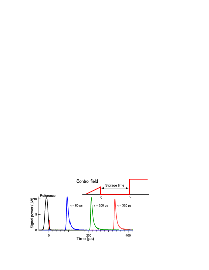
The combination of a dynamic control field and polarization self-rotation can also be applied to stored light lukin03rmp ; fleischhauer00 ; phillips ; mair ; fleischhauer02 , enabling very large fractional pulse delays as shown in Fig. 4. Once a slow-light signal pulse is localized inside the EIT medium, it can be mapped into a stationary collective spin state by adiabatically switching off the control field, and later mapped back into a propagating slow-light pulse by switching the control field back on. Combining this stored light technique with a linear ramp of the control field during entry of the signal pulse into the Rb vapor, as well as integrated gain from polarization self-rotation, we straightforwardly achieved fractional pulse delays with minimal loss and distortion. Further optimization should be possible by customizing the control field temporal profile arkhipkinPRA06 .
In summary, we demonstrated slow and stored light in Rb vapor with minimal loss and pulse distortion and large fractional delay. This behavior is enabled by the use of a medium with (i) a group index that can be controllably varied during light pulse propagation, which allows for large pulse delay and corrects for distortion; and (ii) integrated, independently-controllable gain to offset residual loss. The technique is general and should be applicable to other atomic and solid-state systems, since a controllable group index and gain are common in many materials, including doped crystals manson05 , semiconductor heterostructures ku , and optical fibers patnaik ; linJOSAB04 ; mok ; kaloshaPRA07 .
We are grateful to A.V. Gorshkov, Y. Xiao and M. Klein for useful discussions. This work was supported by ONR, DARPA, NSF, and the Smithsonian Institution.
References
- (1) R. S. Tucker, P. S. Ku, and C. J. Chang-Hasnain, J. Lightwave Tech. 23, 4046 (2005).
- (2) M. D. Lukin, Rev. Mod. Phys. 75, 457 (2003).
- (3) R. W. Boyd and D. J. Gauthier, Progress in Opt. 43, 497 (2002).
- (4) M. S. Bigelow, N. N. Lepeshkin, and R. W. Boyd, Science 301, 200 (2003).
- (5) Y. Okawachi et al., Opt. Express 14, 2317 (2006).
- (6) R. M. Camacho, M. V. Pack, and J. C. Howell, Phys. Rev. A 73, 063812 (2006); ibid.74, 033801 (2006).
- (7) M. Fleischhauer and M. D. Lukin, Phys. Rev. Lett. 84, 5094, (2000).
- (8) D. F. Phillips, A. Fleischhauer, A. Mair, R. L. Walsworth, and M. D. Lukin, Phys. Rev. Lett. 86, 783 (2001).
- (9) A. Mair, J. Hager, D. F. Phillips, R. L. Walsworth, and M. D. Lukin, Phys. Rev. A 65, 031802(R) (2002).
- (10) M. Fleischhauer and M. D. Lukin, Phys. Rev. A, 65, 022314 (2002).
- (11) L. V. Hau, S. E. Harris, Z. Dutton, and C. H. Behroozi, Nature 397, 594 (1999).
- (12) J. J. Longdell, E. Fraval, M. J. Sellars, and N. B. Manson, Phys. Rev. Lett. 95, 063601 (2005).
- (13) D. Mori, S. Kubo, H. Sasaki, and T. Baba, Opt. Express 15, 5264 (2007).
- (14) P. C. Ku, C. J. Chang-Hasnain, and S. L. Chuang, J. Phys. D 40, R93 (2007).
- (15) K. Totsuka, N. Kobayashi, and M. Tomita, Phys. Rev. Lett. 98, 213904 (2007).
- (16) A. K. Patnaik, J. Q. Liang, and K. Hakuta, Phys. Rev. A 66, 063808 (2002).
- (17) Q. Lin and G. P. Agrawal, J. Opt. Soc. Am. B 21, 1216 (2004).
- (18) J. T. Mok, C. M. de Sterke, I. C. M. Littler, and B. J. Eggleton, Nature 438, 775 (2006).
- (19) V. P. Kalosha, L. Chen, and X. Bao, Phys. Rev. A 75, 021802(R) (2007).
- (20) R. W. Boyd, D. J. Gauthier, A. L. Gaeta, and A. E. Willner, Phys. Rev. A 71, 023801 (2005).
- (21) R. Buffa, S. Cavalieri, and M. V. Tognetti, Phys. Rev. A 69, 033815 (2004).
- (22) V. G. Arkhipkin and I. V. Timofeev, Phys. Rev. A 73, 025803 (2006).
- (23) W. V. Davis, A. L. Gaeta, and R. W. Boyd, Opt. Lett. 17, 1304 (1992); S. M. Rochester et al., Phys. Rev. A 63, 043814 (2001).
- (24) A. B. Matsko et al., Phys. Rev. A 66, 043815 (2002); I. Novikova, A. B. Matsko, and G. R. Welch, J. Mod. Opt. 49, 2565 (2002).
- (25) I. Novikova et al., Opt. Lett. 25, 1653 (2000).
- (26) Polarization self-rotation neither relies on ground-state coherence associated with EIT nor affects it and is also present in the absence of any applied magnetic field.