Equation of motion for dislocations with inertial effects
Abstract
An approximate equation of motion is proposed for screw and edge dislocations, which accounts for retardation and for relativistic effects in the subsonic range. Good quantitative agreement is found, in accelerated or in decelerated regimes, with numerical results of a more fundamental nature.
pacs:
61.72.Bb, 61.72.Lk, 62.20.FeI Introduction
Dislocation behavior in solids under dynamic conditions (e.g. shock loading HORN62 ; CLIF81 ; TANG03 ) has recently attracted renewed attention, TANG03 ; HIRT98 ; GUMB99 ; MARI04 ; DENO04 ; PILL06 ; DENO07 partly due to new insights provided by molecular dynamics studies. GUMB99 ; TANG03 ; MARI04 Whereas theoretical investigations mainly focused on the stationary velocities that regular or twinning dislocations can attain as a function of the applied stress (possibly intersonic or even supersonic with respect to the longitudinal wave speed ),WEER69 ; GUMB99 ; ROSA01 one other major concern is to establish an equation of motion ESHE53 ; CLIF81 ; ROSA01 ; HIRT98 (EoM) suitable to instationary dislocation motions towards or from such high velocities, and which is computationally cheap. This would be an important step towards extending dislocation dynamics (DD) simulations DEVI97 ; BULA06 ; WANG06 to the domain of high strain rates, in order to better understand hardening processes in such conditions.
The key to instationary motion of dislocations lies in the inertia arising from changes in their long-ranged displacement field, which accompany the motion. These retarded rearrangements take place at finite speed, through wave emission and propagation from the dislocation. As a consequence, dislocations possess an effective inertial mass,ESHE53 which has bearings on the process of overcoming dynamically obstacles such as dipoles, etc. PILL06 ; WANG06 ; BITZ05 Inertial effects are non-local in time, and are related to effective “viscous” losses. For small velocities where the EoM is linear,ESHE53 this relation takes the form of the Kramers-Krönig relations between the reactive and dissipative parts of the causal mass kernel.NABA51 ; ESHE62 ; ALSH71 One major ingredient of the EoM should thus be the effective visco-inertial force exerted on the dislocation by its own wave emission.ESHE53 ; CLIF81 An EoM results from balancing it by the applied stress, and by drags of various origins.ALSH86 EoMs with effective masses, but which ignore retardation (e.g., Ref. HIRT98, ), cannot truly capture visco-inertial effects. Previous works on these questions having mainly been confined to the linear regime, their influence in the relativistic domain remains largely unexplored in spite of analytical progresses, partly due to the complexity of the formalism (especially for edge dislocations).
Hereafter, Eshelby’s EoM for screws with a rigid core,ESHE53 valid at small velocities, is first re-examined, and cast under a simple form which suggests a straightforward regularization procedure for finite core effects. This allows us to appeal to previous results for point dislocations valid at high velocities.CLIF81 We then build in an heuristic way an EoM for accelerated or decelerated screw and edge dislocations in the drag-dominated subsonic regime, that consistently accounts for saturation effects at velocities comparable to the sound speed. Results from the equation are compared to quasi-exact calculations from a numerical method of the phase-field type. Having in mind applications to DD simulations, the scope of the study is limited to continuum theory, so that dispersion effects due to the atomic lattice,ISHI73 or to the influence of the Peierls potential,ALSH71 are not explicitly considered.
II Eshelby’s force
Within the Peierls-Nabarro model in isotropic elasticity,PEIE40 ; NABA47 and with the usual ansatz for the relative displacement of the atoms on both sides of the glide plane, Eshelby computed the visco-inertial force experienced by a screw dislocation of Burgers vector , centered on position at time , moving with a velocity small compared to the shear wave speed :ESHE53
| (1) | |||
The dislocation is assumed to have a rigid core of half-width . Then is the time of shear wave propagation over the core width. The mass per unit dislocation length depends on the shear modulus . In Ref. ESHE53, (and in Ref. ALSH71, as well), an incorrect factor is present in front of the second integral, and has been removed here. This factor is of no important physical consequence, save for different values of the linear response kernels; see below.
That (1) is correct can be verified as follows. Starting from Eshelby’s expression of the force as a double integral in Eq. (26) of Ref. ESHE53, , and expanding it to linear order in the velocity or in , the following expression is easily obtained:
| (2) | |||||
where . Using integrations by parts over , each of Eq. (1) and (2) can be put under the following irreducible form:
| (3) |
which shows them to coincide.
By the same token, we check that (1) can be further simplified as:
| (4) |
By Fourier transforming [under the form (3)] and by writing
we identify effective mass and viscosity kernels. NABA51 Their expression in closed form involves the modified Bessel and Struve functions , and :
| (5a) | |||||
| (5b) | |||||
To leading orders in the pulsation ,
| (6a) | |||||
| (6b) | |||||
where is Euler’s constant. Moreover, we observe that
| (7) |
Result (6) coincides to leading order with Eshelby’s, ESHE53 as . The mass increase with wavelength as implies very different behaviors for, e.g., quasi-static and shock loading modes, since the latter involves a wider frequency range. We note that as , since losses should be absent from the model in the stationary subsonic regime. ESHE53 The non-analytical behavior of the kernels at (due to ), and its associated non-locality in time has been emphasized in Ref. ALSH71, .
The finite “instantaneous” viscosity (7) stems from the first term in the R.H.S. of (3), and is responsible for a velocity jump undergone by the dislocation when subjected to a jump in the applied force.ESHE53 ; CLIF81 From (7) we deduce:
| (8) |
The velocity jump (8) increases with core width. It was first predicted by Eshelby from his equation,ESHE53 and can be understood as follows for a screw dislocation along the axis: the force jump is due to a shear stress jump attaining simultaneously all the points of the whole glide plane (e.g., as the result of shear loading applied on faces of the system containing the plane, parallel to the latter). Neglecting material inertia of the atoms on both sides of the dislocation plane, the medium undergoes an elastic strain jump , determined by a material velocity jump . The latter is equilibrated through outward emission of a shear wave with velocity . On the other hand, the slope of the displacement function near the core is , so that is related to the dislocation velocity jump by . Combining these relationships yields (8), up to a numerical constant factor. The same argument applies to other types of dislocations. In case of several relaxation waves (e.g., longitudinal and shear waves for an edge dislocation), that of lowest celerity controls the amplitude of the velocity jump. It should be borne in mind, however, that accounting for material inertia from the atoms on both sides of the glide plane results in an instantaneous inertial force of order to be added to (1).ESHE53 By balancing the forces, it is seen that this force should spread the velocity jump over a short rise time
| (9) |
III Equation of motion
No expression analogous to (1) is available for edge dislocations. However, Clifton and Markenscoff computed the force acting on a point screw or edge dislocation moving with any subsonic velocity in an isotropic medium, that jumps instantaneously at instant from rest to a constant velocity .CLIF81 A generalization to anisotropic media is available.WU02 To maintain its velocity constant, this dislocation must be subjected, at time , to the time-decaying force
| (10) |
where the function depends on its character and on anisotropy. ESHE53 ; CLIF81 We now construct heuristically a force for accelerated motion by interpreting such a motion as a succession of infinitesimal velocity jumps. Assuming that, for instationary motion, in (10) can be interpreted as , the elementary force that would arise from the elementary jump at is: . Then, the total force experienced by the dislocation results from integrating such elementary forces over past history:
| (11) |
Comparing (11) to (4) shows, firstly, that the relevant “accelerations” at linear order are different. However, we remark that as , and moreover that for a screw dislocation, . CLIF81 Hence, since we interpret in (10) as , the numerator of the integrand in (11) is correct at least for small velocities and for small times . Its relevance for large velocities is demonstrated below through comparisons to full-field calculations. Next, integral (11) is singular at , due the point-dislocation hypothesis at the root of (10). However, using (4) as a physical motivation, we propose a regularization consisting in replacing the kernel in (11) by where , the counterpart of in (1), is some time characteristic of sound propagation over a core diameter. In Sec. IV, is chosen alternatively proportional to and to in the case of edge dislocations for illustrative purposes, whereas is proportional to for screws. The proportionality factor, 1/2 in all cases, is justified below. From a physical point of view, inertia is controlled by the slowest wave so that better results are expected using for all types of dislocations. Given Eshelby’s rigid-core hypothesis in (4), and the approximations made, it would be pointless to refine this treatment. Another kind of regularization is used in Ref. HIRT82, (p. 195), which consists in replacing the upper bound of integral (11) by (in Ref. HIRT82, , the integrand assumes that ).
With the above regularization the force eventually reads:
| (12) |
Its Fourier transform for small velocities where yields, in terms of modified Bessel and Struve functions of order 0,
| (13b) | |||||
| (13c) | |||||
The approximation therefore preserves the logarithmic character of the mass, and the viscosity, to leading order. The mass is slightly decreased, the constant in (6a) being absent. This difference is insignificant given the approximations made. In the limit of small velocity for a screw dislocation, our approximation amounts to retaining in (1) the first integral only. In order to recover a correct velocity jump for screws, we must take since the instantaneous viscosity (13c) is different from (7). This “calibration” is used in the next section for screws and (somewhat arbitrarily) for edges as well.
In the stationary limit, the visco-inertial force (12) vanishes. For , the asymptotic velocity should be determined by a viscous drag force, mainly of phonon origin,ALSH86 , where is the viscosity. This force is modified (in the context of the Peierls-Nabarro model) by the relativistic contraction of the core, into . For subsonic velocities, , where:ROSA01
| (14) |
with , is an effective viscosity-dependent core contraction factor, such that the core length in the laboratory frame reads: . The purely relativistic contraction factor is, with :WEER61 ; ESHE49 ; ROSA01
With this drag, and introducing the applied stress , the EoM finally reads:
| (15) |
where , and where:CLIF81
This is our main result. By construction, it reproduces the asymptotic velocities of Ref. ROSA01, .
We checked numerically that the replacement of by in does not change by more than a few percent the overall results described in the following section. Since this change in would bring in nothing useful, we choose to use in in the following section.
IV Applications
Setting , Eq. (15) is solved numerically for edge and screw dislocations, in an implicit way with a time step small enough. Results are compared with numerical points obtained with the Peierls-Nabarro-Galerkin (PNG) approach DENO04 ; DENO07 used here as a benchmark. This method is less noisy than molecular dynamics, allows for full-field dynamic calculations of the displacement and stress fields in the whole system, accounting for wave propagation effects, and allows for better flexibility. We can thus, e.g., control boundary conditions by applying analytically computed forces, so as to prevent image dislocations from perturbing the simulation window.
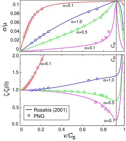
Firstly, to check the accuracy of the benchmark, asymptotic velocities of screw and edge dislocations were compared to the stationary predictions of Rosakis’ Model 1.ROSA01 In the PNG method, the permanent lattice displacement field (which is part of the full atomic displacement, ) is relaxed by means of a Landau-Ginzburg equation, with viscosity parameter . An exact correspondence holds between this viscosity and Rosakis’s viscosity parameter , namely , as can be shown by specializing to one dimension the general field equations of Ref. DENO04, . A -potential , with , is used. The material is an elastically cubic material, with elastic moduli taken such that to insure isotropy. Due to the elastic correction made to the -surface potential in order to remove its quadratic elastic part,DENO04 ; DENO07 the core at rest is a bit larger in the PNG results than in the Peierls-Nabarro solution. The time dependent core width is measured from the numerical simulations by using (the value corresponding to a core of the arctan type). Two-dimensional calculations are carried out using a simulation box of size , with a unique horizontal glide plane along . Eight nodes per Burgers vector are used in both directions. Forces are applied on the top and bottom sides so as to induce shear on the unique glide plane. Free boundary conditions are used on sides normal to the axis. Measurements are done near the center of the box, where the mirror attracting forces these sides generate on the dislocation, are negligible. The box is wide enough so that the dislocation accelerates and reaches its terminal velocity. Comparisons between PNG results and Rosakis’ model are displayed in Fig. 1 for different viscosities , in the case of an edge dislocation. The core scaling factor and the asymptotic velocity , are directly measured from simulations under different applied stresses , and compared to theory. ROSA01 The PNG asymptotic velocities were found to be systematically lower than the theoretical results. This correction is accounted for in the figure. The overall agreement is excellent. It is emphasized that core contraction effects in the viscous drag [Eq. (14)] are required in order to obtain a good match.
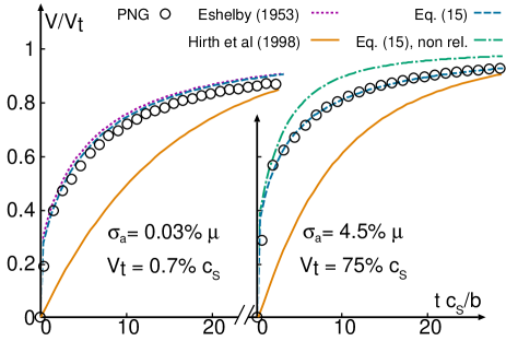
Next, comparisons in the accelerated regime are made with Eq. (15) and with other models. Fig. 2 displays, as a function of time, the velocity of a screw dislocation accelerated from rest by a constant shear stress applied at . Low and high shear stresses are examined. These stresses lead to terminal asymptotic velocities and , computed from (15). The results displayed are obtained: (i) with the PNG approach (white dots); (ii) with Eq. (15) using fully “relativistic” expressions of and (dashes); (iii) with linear small-velocity approximations of , but with the full expression of , in order to emphasize the importance of relativistic effects in the retarded force (dash-dots, for the case ); (iv) with a previous EoM,HIRT98 using a typical cut-off radius nm in the logarithmic core term (solid) corresponding to a typical dislocation density of /m2. The result arising from using (1) in the EoM is also displayed for the lowest speed (dots, left figure only).
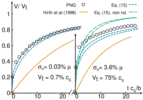
Figure 3 presents similar curves for an edge dislocation. For the latter, is taken either as or as , , thus providing two limiting curves. The curves with provide the best matches, consistently with the above observation that the wave of lowest velocity should provide the main contribution to inertia. At low and high speeds, good agreement is obtained between PNG points and Eq. (15), provided that fully “relativistic” expressions are used for (especially for edge dislocations); otherwise, inertia is strongly underestimated. In all the curves, the relativistic expression of the non-linear viscous terms was used. Moreover, variations of the core width with velocity,ROSA01 implicitly present in PNG calculations, and ignored in the expression of used in the visco-inertial term of (15), are not crucial to accelerated or to decelerated motion (see Fig. 4); still, the core width shrinks by 20% during the acceleration towards . On the other hand, retardation effects in the effective mass are crucial: curves with non-local inertial forces are markedly different from the solid ones using the masses of Ref. HIRT98, , computed at constant velocity. The version of the PNG code used here does not include the above-mentioned effects of material inertia in the glide plane, so that the full-field velocity curves indeed display what resembles a velocity jump, like the EoM. Owing to (9), this lack of accuracy solely concerns the time interval between the time origin and the first data point: hence we can consider that the velocity jump is a genuine effect, and not an artefact, at least from the point of view of full-field calculations in continuum mechanics. However, we should add that, to our knowledge, this effect has not been reported so far in molecular dynamics simulations.
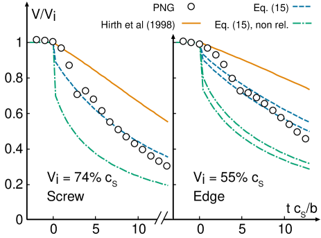
Figure 4 displays the velocity of screw and edge dislocations decelerated from the initial velocity . Comparisons between EoMs and PNG calculations are then harder to make than in the accelerated case. Indeed, the non-relativistic (resp. relativistic) theoretical curves from Eq. (15) (dashed-dot) [resp. (dashed)] are obtained by assuming that an applied stress abruptly vanishes at . This induces a negative velocity jump in the curves. This jump is larger if non-relativistic expressions are used, which demonstrates in passing the higher inertia (i.e. “mass”) provided by relativistic expressions. The same loading was tried in the PNG calculations as well, but led to non-exploitable results due to multiple wave-propagation and reflection phenomena. Therefore, PNG curves for decelerated motion were obtained instead using a somewhat artificial loading: the medium was split in a zone of constant stress, separated from a zone of zero stress by an immobile and sharp boundary. The dislocation is then made to accelerate in the zone of constant stress. Due to the finite core width, the boundary is crossed in a finite time , which explains the smoothed decay of the velocity in the PNG data points. This type of loading cannot be realistically implemented within the framework of Eq. (15) because the dislocation core is not spatially resolved. Hence, though the curves strongly suggest that relativistic effects are as important in deceleration as in acceleration, and that (15) reproduces well the PNG points, the comparison between the latter and theoretical curves should be taken here with a grain of salt. On the other hand, the EoM of Ref. HIRT98, (solid) is once again clearly imprecise. As a final remark, we expect our neglecting of retardation effects in the nonlinear viscous term of (15) to induce an underestimation of damping effects. This may explain why the PNG curves decay faster than that from Eq. (15).
V Concluding remarks
An empirical relativistic equation of motion for screw and edge dislocations, accounting for retardation effects in inertia, Eq. (15), has been proposed. We compared it, together with another available approximate EoM, to a quasi-exact numerical solution of a dynamical extension of the Peierls-Nabarro model, provided by the Peierls-Nabarro Galerkin code.DENO07 The latter was beforehand shown to reproduce very well the asymptotic velocities of Rosakis’s model 1ROSA01 in the subsonic regime. The best matches with full-field results were found with our EoM, both for accelerated and for decelerated motion, thus illustrating quantitatively the importance of retardation and of relativistic effects in the dynamic motion of dislocations. To these effects, our EoM provides for the first time a satisfactory approximation for high velocities in the subsonic range. Our comparisons rule out the use of masses computed at constant velocity. One of the restrictions put forward by Eshelby to his EoM was its limitation to weakly accelerated motion, mainly due to the rigid core assumption.ESHE53 Ours makes no attempt to explicitly overcome this simplification. However, comparisons with full-field calculations, where the core structure is not imposed from the start, but emerges as the result of solving the evolution equation for the displacement field, shows that this rigid-core assumption is acceptable on a quantitative basis as far as inertia is concerned, at least for velocities high, but not too close to .
Acknowledgements.
The authors thank B. Devincre for stimulating discussions, and F. Bellencontre for his help during preliminary calculations with the PNG code.References
- (1) E. Hornbogen, Acta Metall. 10, 978 (1962).
- (2) R.J. Clifton and X. Markenscoff, J. Mech. Phys. Solids. 29, 227 (1981).
- (3) D. Tanguy, M. Mareschal, P.S. Lomdahl, T.C. Germann, B.L. Holian and R. Ravelo, Phys. Rev. B 68, 144111 (2003).
- (4) J.P. Hirth, H.M. Zbib and J.P. Lothe, Modelling Simul. Mater. Sci. Eng. 6, 165 (1998).
- (5) P. Gumbsch and H. Gao, Science 283, 965 (1999).
- (6) J. Marian, W. Cai and V.V. Bulatov, Nature Materials 3, 158 (2004).
- (7) C. Denoual, Phys. Rev. B 70, 024 106 (2004).
- (8) L. Pillon, C. Denoual, R. Madec and Y.-P. Pellegrini, J. Phys. IV (France) 134, 49 (2006).
- (9) C. Denoual, Comput. Methods Appl. Mech. Engrg. 196, 1915 (2007).
- (10) J. Weertman in Mathematical theory of dislocations, edited by T. Mura (ASME, New York, 1969), p. 178.
- (11) P. Rosakis, Phys. Rev. Lett. 86, 95 (2001).
- (12) J.D. Eshelby, Phys. Rev. 90, 248 (1953).
- (13) B. Devincre and L.P. Kubin, Mater. Sci. Eng. A 234-236, 8 (1997).
- (14) V.V. Bulatov, L.L. Hsiung, M. Tang, A. Arsenlis, M.C. Bartelt, W. Cai, J.N. Florando, M. Hiratani, M. Rhee, G. Hommes, T.G. Pierce and T. Diaz de la Rubia, Nature 440, 1174 (2006).
- (15) Z.Q. Wang, I.J. Beyerlein and R. LeSar, Los Alamos preprint LA-UR-06-3602 (unpublished).
- (16) E. Bitzek and P. Gumbsch Mater. Sci. Eng. A 400, 40 (2005).
- (17) J.D. Eshelby, Proc. R. Soc. London, Ser. A 266, 222 (1962).
- (18) V.I. Al’shitz, V.L. Indenbom and A.A. Shtol’berg, Zh. Eksp. Teor. Fiz. 60, 2308 (1971) [Sov. Phys. JETP 33, 1240 (1971)].
- (19) F.R.N. Nabarro, Proc. R. Soc. London, Ser. A 209, 278 (1951).
- (20) V.I. Alshits and V.L. Indenbom, in Dislocations in Solids vol. 7, edited by F.R.N. Nabarro (North-Holland, Amsterdam, 1986).
- (21) S. Ishioka, J. Phys. Soc. Japan 34, 462 (1973).
- (22) R. Peierls, Proc. Phys. Soc. 52, 34 (1940).
- (23) F.R.N. Nabarro, Proc. Phys. Soc. 59, 256 (1947).
- (24) K.C. Wu, Acta Mechanica 158, 85 (2002).
- (25) J.P. Hirth and J.P. Lothe, Theory of crystal dislocations (Krieger, New York, 1982).
- (26) J. Weertman, in Response of materials to high velocity deformations, edited by P.G. Shewmon and V.F. Zackay (Interscience, New York,1961), p. 205.
- (27) J.D. Eshelby, Proc. Phys. Soc. A 62, 307 (1949).