A diffraction-compensating 0–25 ns free space terahertz delay line for coherent quantum control
Abstract
Free space delay lines provide pulses of variable time spacing for optical experiments such as pump-probe spectroscopy and coherent quantum control, including spin and photon echo techniques. However, in the terahertz (THz) region of the spectrum, beam divergence due to diffraction limits the useful length of traditional free space delay lines. We present a novel double-folded variable delay line for light in the frequency range 0.24–1.2 THz, which incorporates a symmetric arrangement of lenses whose spacing can be adjusted to compensate for diffraction at each delay. Scalable for use in other wavelength regimes, the design relays an input Gaussian beam waist to the output with up to 25 ns ( m) total delay and is enclosed in a desiccated volume of m3. The delay line can deliver two or three pulses with relative amplitudes controlled via variable spacing silicon etalon beam splitters. Beam profiles of a 0.24 THz beam show good agreement with calculations at long delays, with insertion loss per delay stage of dB.
The quest for higher spectral resolution, higher sensitivity and faster time response has driven state of the art electron paramagnetic resonance (EPR) beyond microwaves, to the edge of the terahertz (THz) regimeFreed (200). At the same time, the search for a qubit with suitably low decoherence rates and potential scalability for quantum information processing has led some researchers to the same technologically under-serviced spectral rangeSherwin et al. (1999); Smelyanskiy et al. (2005). In both fields, pulsed quantum control techniques allow measurements of population relaxation (via time-resolved decay of magnetization or emission), ensemble dephasing (via decay of Rabi oscillations versus pulse intensity or duration), and decoherence (via the decay of a spin or photon echo). Such measurements yield information about local environments and interactions at the nanoscale, and are being pursued at terahertz frequencies for studies of protein conformal dynamics using amino acid spin labels and dynamics of electrons in quantum confined nanostructures. We note the application of these techniques is predicated on the availability of high intensity radiation delivered in pulses of well-defined shape, controllable amplitude and variable time delay.
In the optical and infrared regions of the spectrum, free space delay lines utilize a beamsplitter to direct a portion of an optical pulse along variable path length, , terminated by retroreflecting mirror arrangement, which offsets the pulse and returns it along a parallel trajectory. The reflected portion is delayed relative to the incident pulse by , where is the speed of light. At the other end of the spectrum, below 0.1 THz, waveguided microwave devices are preferred over free space delays for pulse generation.
In the intermediate range 0.1–10 THz, neither ray optics solutions nor waveguided circuit technologies for pulse generation are generally applicable. This is due to a conspiring collaboration of failing material properties and the breakdown of most of the useful approximations that make microwave and photonics tools readily engineerable. THz sources based on semiconductor transport including Schottky diode multipliers111Commercially available from, e.g., Virginia Diodes, Inc.. and quantum cascade lasersWilliams et al. (2005) can be modulated by microwave techniques, but do not yet provide adequate power for most quantum control experiments. Thus, quasi-optical sources and pulse generating techniques are required for most nonlinear and quantum control experimentsCarter et al. (2005). In such quasioptical systems, beam diffraction and water vapor absorption are primary concerns.
Here we describe a folded, dry atmosphere delay line which compensates for diffraction, enabling delay paths of up to m ( ns) for wavelengths as long as mm in compact 2x0.5 m footprint. The delay line is designed as dual use instrument for studies of quantum dynamics of electrons confined by impurity centersCole et al. (2001), quantum well heterostructures and quantum dots, and as part of a high field, 240 GHz pulsed EPR (a.k.a. ESR) spectrometer under collaborative development by the UCSB Center for Terahertz science and Technology and the National High Magnetic Field Laboratory, FloridaTakahashi et al. (2007). The delay line delivers two controllable amplitude pulses of variable delay (i.e. , ) for Hahn echo measurements (spin or photon echo), or three pulses of equal time delay (, , ) for projecting Hahn echoes onto population differences, which is useful when quantum nondemolition readout techniques are available for measuring populations directlyAllen et al. (2005).
The approach taken in the present work is reminiscent of an optical delay line, with the addition of a set of symmetrically placed lenses whose relative spacing can be varied to compensate for diffraction over a wide range of delays. The working principle is based on the fact that the effective focal power of a composite lens depends on the spacing between the elements (Fig. 1). Consider a composite lens comprised of a negative lens of focal length , flanked by two positive lenses each with focal length , which are positioned equal distances away from the negative lens. Such an arrangement can be used to relay or “refocus” a Gaussian beam. However, when placed together to form a single block, the composite lens exhibits no significant transformation on an incident beam. This symmetric lens arrangement is implemented in our delay line because it provides diffraction compensation over the widest possible range of delays, as explained below.
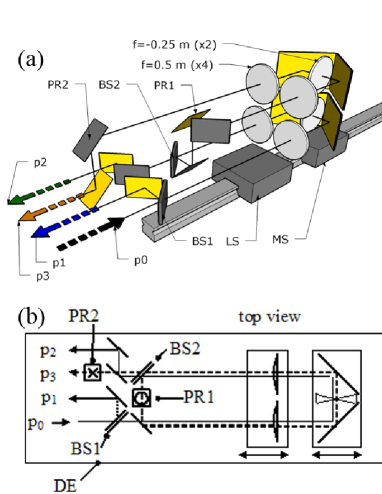
In the present design (Fig. 2) bending mirrors are placed between two plano-convex 0.5 m focal length lenses and a m focal length biconvex lens. The mirrors and negative lens are mounted to a sliding carriage on a precision rail. The location of the sliding carriage along the rail determines the length of the delay path. The sliding carriage is moved via a computer-controlled stepper motor and timing belt with limit and home switches to forestall collisions and ensure repeatably referenced positioning. The positive focal length lenses are mounted pair-wise on a separate computer-controlled slider. At each delay, the position of the positive lens carriage can be set to relay to the output a Gaussian beam with a waist near the input. Other lens arrangements are possible for achieving the same effect, such as putting two or three lenses in one arm of the delay. However, the symmetric embodiment was chosen because (1) it requires only two moving stages, (2) if more rail sliders were needed for focusing, the additional thickness of the sliders would limit the minimum path length/delay, and (3) most importantly for long wavelength radiation, the symmetric design can be folded back and stacked on top of itself, without the addition of more moving stages. This is desirable to prevent a diffracting beam from becoming unmanageably large in the course of a long delay path
The layout is simultaneously constrained by a number of experimental requirements. These include a desired small physical separation of the delayed pulses (which limits the maximum input beam diameter) and the maximum lens size (which simultaneously determines the minimum return beam offset and minimum lens spacing) .These first two requirements (beam input size and maximum beam diameter) fix the maximum delay that can be accommodated for a given wavelength. The additional requirements that a third pulse be twice the delay of the second pulse and that all outgoing pulses have similar beam waist diameters constrain the placement of the input beam waist location relative to the two beamsplitters.
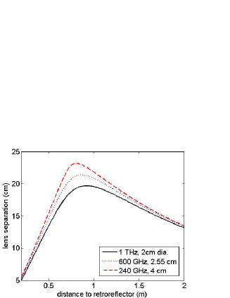
The optimal lens carriage position for relaying (“focusing”) a delayed beam is calculated using the “q” parameter methodKogelink and Li (1966), which is valid in the paraxial approximation. The thickness of the lenses can be treated within this formalism but the effect of finite lens thickness was found to be negligible in the present design. The cross section of the input beam is assumed to be a Gaussian intensity profile, and is characterized by two parameters: beam waist radius, and radius of curvature. The “focal” condition requires the outgoing, delayed beam have the same beam waist radius and radius of curvature as the incident beam. This is sufficient to determine the required spacing between the positive and negative lenses. The focal lengths of the lenses are chosen such that the spacing required to focus at short delays is not less than the minimum allowed by the interpositioned bending mirrors. The required lens separation is then calculated given the delay, the lens focal lengths, and minimum beam waist radius (Fig. 3).
The maximum delay per delay line is 12.8 ns (25.6 ns total). The minimum delay per delay line is limited by the minimum lens spacing, and is dependent on operating wavelength, falling in the range 3.5–4 ns. The lenses are kinematically located and can be removed from the beam path for visible alignment, and for use at frequencies which do not require diffraction compensation. The delay line contains two variable beam splitters (Fig. 2, BS1 and BS2), which can be removed or replaced with fixed ratio wire mesh beam splitters or fully reflecting mirrors. A variety of configurations are possible. With the second beamsplitter removed, the delay line produces two pulses of relative delay 3.5–12.8 ns. With a mirror at the position of the beamsplitter, two pulses are delivered with delays of 7-25.6 ns. Additionally, an extra 3.5 ns compensating path was designed with diffraction compensating lenses, which can be inserted in the path of the undelayed beam (Fig 2, ) to produce pulse of delay 0–9.3 ns or 3.5-22.1 ns. With the variable second beamsplitter in place, three pulses are generated, which are separated by equal, variable delays of 3.5–12.8 ns.
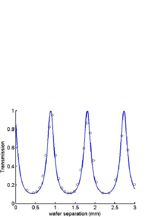
For pulses of nanosecond duration, an etalon-based variable beam splitter is used to control the relative intensities reflected by the first beamsplitter (Fig. 2, p1) and transmitted by the second beamsplitter (Fig. 2, p3). The etalon is comprised of two closely spaced 500 m thick Si wafers at 45 degree incidence. The wafer spacing can be adjusted via a translation stage to achieve transmission in the range 0.1–1 (reflectivity 0–0.9) (Fig. 4). For shorter pulses in the tens to hundreds of picoseconds time scale, fixed beam splitters based on wire meshes should be used, as multiple reflections from the four interfaces in the etalon would distort and stretch the pulse.
The lenses are cut from 100 mm diameter polypropylene (PPE) round stock on a CNC lathe, and the mirrors are fabricated in a cost-effective manner by e-beam depositing 600 nm of Au on 650 m thick polished Si wafers with a 20 nm Ti or Cr adhesion layer. During operation at frequencies above 0.5 THz, a diaphragm pump is used to continuously circulate the enclosed 0.5 m3 volume of air through an air dryer/filter, such as is commonly used in compressed air lines. Atmospheric moisture, as measured by a NIST traceable hygrometer, is reduced from ambient 40% to less than 1% relative humidity in approximately 45 minutes.
The delay line is tested with 240 GHz solid state frequency source based on Schottky diode multipliers that is coupled to a free space TEM00 Gaussian mode via a corrugated feedhorn. The source passes through two lenses which match the Gaussian beam to produce a minimum beam waist diameter of 2 cm at the input of the delay line (Fig. 2, BS1), which enables us to examine the effect of unmodeled nonidealities. The most significant nonidealities include (1) alignment error, (2) input beam parameter uncertainty, (3) wavefront distortion due to thickness dependent loss in the PPE lenses, (4) successive clipping of the beam peripheral fields by mirrors and lenses of size on the order of the beam waist diameter, (5) the paraxial approximation, and (6) lens and mirror defects due to material inhomogeneity, manufacturing defects and strained mounting. The delayed beam is profiled via a rastering pyroelectric detector of size 2 mm on a side. The metal housing is carefully shielded with black THz absorbing foam to prevent feedback on the source. Prior to passing through two input matching lenses, the beam is indistinguishable from a perfect Gaussian. Afterward, the center of the beam profile is slightly flattened due to loss from passing through several millimeter thick 0.25 m and -0.5 m focal length PPE lenses (Fig. 5a).
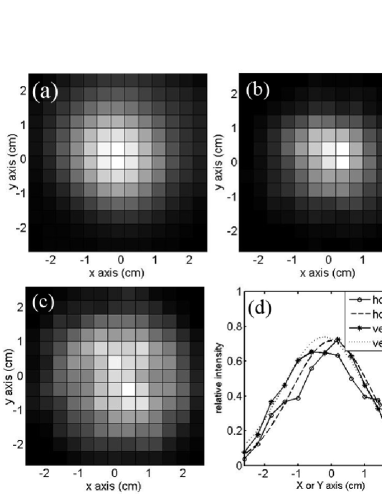
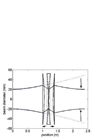
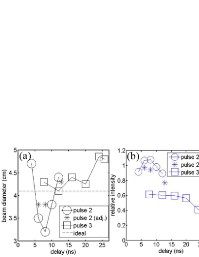
Figure 5b–c show the output beam profiles at locations p2 and p3 in Figure 2, at short and long delays, respectively. The beam width of a series of beam profiles, estimated by a fit to a Gaussian profile (e.g. Fig. 5d), and plotted in Fig. 6a, alongside the integrate intensity (Fig. 6b). At short delays over focusing is noticeable, relative to the expected result from q-parameter simulations. This is attributed to distortion of the beam intensity profile by thickness-dependent loss in the polypropylene lenses. The difference in lens thickness between the center and edge of the beam is most pronounced in the positive lenses, where the beam is large. The center part of the beam experiences more absorption, which results in a flattened intensity profile that requires less diffraction compensation than the Gaussian profile assumed by the Q-parameter method. The effect is only partially compensated by the negative lens, since the beam diameter is much smaller at the negative lens. At longer delays, the return beam is slightly wider than expected. This is due to the far field diffraction from non-Gaussian components (i.e. M) in the intensity profile introduced by the thickness dependent lens loss, as well as clipping of peripheral fields by mirrors of size on the order of the beam diameter, as evidenced by the negative slope in figure 6a at delay times corresponding to long delay paths.
The total power in the delayed beams is reduced by a factor of 0.5 per delay stage, attributable primarily to reflection from the six lens surfaces which are not antireflection coated, secondarily to lens absorptionJin et al. (2006), and lastly to diffraction losses. While this seems large in comparison to losses achievable in the optical regime, the utility of a compact, desiccated delay line becomes apparent when compared to the typically much higher losses of THz beams traversing the similar distances in a nondesiccated atmosphere.
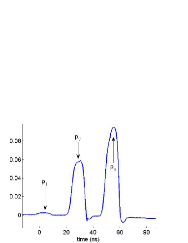
The delay of short pulses is demonstrated via use of fast PIN diode to switch the 15 GHz microwave oscillator that seeds the multiplier chain of the 240 GHz source, producing single triggered pulses of 10 ns duration and 10 mW average power, which are detected via a Schottky diode (Fig. 7).
Future quantum control experiments will employ the existing UCSB free electron laser (FEL) as a frequency-tunable source providing kilowatts of peak power, together with an optical pulse slicing systemHegmann and Sherwin (1996) which delivers single THz pulses of variable (3 ps–3 ns) duration at a 1–10 Hz repetition rate. The sliced FEL pulse will enter the delay line and emerge as two or three THz pulses of similar size, with variable intensity and delay suitable for Hahn echo and other pulsed coherent control techniques.
We emphasize that the delay line design presented herein is optimal for a subset of applications requiring time delayed THz pulses. There exist a variety of techniques for THz pulse generation and delay based on the timing of optical pulses, including photo-activated semiconductor switchesAlcock et al. (1975); Hendry et al. (2007), and THz generation via ultrafast pulses in nonlinear crystalsLee et al. (2003). When possible, THz pulse generation based on optical pulse timing is preferred because optical delay lines do not required diffraction compensation. In situations where optically gated technologies cannot produce the correct pulse shape or timing, a number of methods for physically delaying THz beams can be used. For fixed delay applications, diffraction in a THz beam can be managed via waveguides based on polymer, metal or semiconductor wires or ribbonsYeh et al. (2005); Mendis and Grischkowsky (2000); Deibel et al. (2006). For power hungry applications, intolerable waveguide dielectric losses and insertion loss are the primary concern. In long travel Michelson interferometers, arrays of corner cube retroreflectors compensate for diffraction by piecewise retroreflecting the face of a divergent beam. However, Michelson interferometers back reflect half the incident power and provide no offset of the return beam, resulting in a train of decaying pulses, rather than dividing the power between only two pulses. Deformable mirrors are another technology which may potentially be leveraged to provide diffraction compensation.
Future implementations of a diffraction compensating THz delay line will benefit by using Fresnel lenses, which can be thinner, and will cause less distortion of the Gaussian beam profile from thickness-dependent loss. Additionally, for nonideal beams where diffraction cannot be satisfactorily managed to produce a constant intensity of pulses versus delay, a method for compensating a change in power with changes in delay should be implemented. One such option would be inserting a variable attenuator/reflector in each of the two delay lines. Another alternative is to use one variable attenuator and motorize the etalon beamsplitters to compensate for measured changes in output power. An alternative layout suitable for 2D NMR-type experiments in which the delay of a third pulse is varied independently of the second pulse, could oppose or juxtapose two independent delay lines, with similar beam splitters and sliding lens carriages. These solutions coupled with the presented method for diffraction compensation will provide suitable pulses and delays for coherent control experiments in the sub-mm and THz spectral ranges.
The authors gratefully acknowledge funding through National Science Foundation grants NSF-CCF 0507295 and NSF-DMR 0507295.
References
- Freed (200) J. H. Freed, Annu. Rev. Phys. Chem. 51, 655 (200).
- Sherwin et al. (1999) M. S. Sherwin, A. Imamoglu, and T. Montroy, Phys. Rev. A. 60, 3508 (1999).
- Smelyanskiy et al. (2005) V. N. Smelyanskiy, A. G. Petukhov, and V. V. Osipov, Phys. Rev. B 72, 08134 (2005).
- Williams et al. (2005) B. Williams, S. Kumar, Q. Hu, and J. Reno, Opt. Express 13, 3331 (2005).
- Carter et al. (2005) S. G. Carter, V. Birkedal, C. S. Wang, L. A. Coldren, A. V. Maslov, D. S. Citrin, and M. S. Sherwin, Science 310, 651 (2005).
- Cole et al. (2001) B. E. Cole, J. B. Williams, B. T. King, M. S. Sherwin, and C. R. Stanley, Nature 410, 60 (2001).
- Takahashi et al. (2007) S. Takahashi, G. Ramian, M. S. Sherwin, L.-C. Brunel, and J. van Tol, submitted to Appl. Phys. Lett. (arXiv:0706.1116v1) (2007).
- Allen et al. (2005) D. G. Allen, M. S. Sherwin, and C. R. Stanley, Phys. Rev. B 72, 035302 (2005).
- Kogelink and Li (1966) H. Kogelink and T. Li, Appl. Opt. 5, 1550 (1966).
- Jin et al. (2006) Y.-S. Jin, G.-J. Kim, and S.-G. Jeon, Jour. Kor. Phys. Soc. 49, 513 (2006).
- Hegmann and Sherwin (1996) F. A. Hegmann and M. S. Sherwin, International Conference on Millimeterand Submillimeter Waves and Applications III (1996).
- Alcock et al. (1975) A. J. Alcock, P. B. Corkum, and D. J. James, Appl. Phys. Lett. 27, 680 (1975).
- Hendry et al. (2007) E. Hendry, M. J. Lockyear, J. G. Rivas, L. Kuipers, and M. Bonn, Phys. Rev. B 75, 235305 (2007).
- Lee et al. (2003) Y.-S. Lee, N. Amer, and W. C. Hurlbut, Appl. Phys. Lett. 82, 170 (2003).
- Yeh et al. (2005) C. Yeh, F. Shimabukuro, and P. H. Siegel, Appl. Opt. 44, 5937 (2005).
- Mendis and Grischkowsky (2000) R. Mendis and D. Grischkowsky, J. Appl. Phys. 88, 4449 (2000).
- Deibel et al. (2006) J. A. Deibel, K. Wang, M. D. Escarra, and D. M. Mittleman, Opt. Express 14, 279 (2006).