The ATLAS Level-1 Trigger: Status of the System and First Results from Cosmic-Ray Data
Abstract
The ATLAS detector at CERN’s Large Hadron Collider (LHC) will be exposed to proton-proton collisions from beams crossing at 40 MHz. At the design luminosity of there are on average 23 collisions per bunch crossing. A three-level trigger system will select potentially interesting events in order to reduce the read-out rate to about 200 Hz. The first trigger level is implemented in custom-built electronics and makes an initial fast selection based on detector data of coarse granularity. It has to reduce the rate by a factor of to less than 100 kHz. The other two consecutive trigger levels are in software and run on PC farms. We present an overview of the first-level trigger system and report on the current installation status. Moreover, we show analysis results of cosmic-ray data recorded in situ at the ATLAS experimental site with final or close-to-final hardware.
, , , , , , , , , , , , , , , , , , , , , , , , , , , , , , , , , , , , , , , , , , , , , , , , , , , , , , , , , , , , , , , , , , , , , , , , , , , . , , , , , , , , , , , , , , , , , , , , , , , . , , , , , , , , , , , , , , , , , , , , , , , , , , , , , , , , , , , , , , , , , , , , , , , , , , , , , , , , , , , , , , , , , , , , ,
1 Introduction
A three-level trigger system was designed for the ATLAS experiment to reduce the initial rate of 40 MHz to 100-200 Hz, a rate digestible by the online-processing and archival-storage facilities. The trigger system aims at retaining potentially interesting events by selecting signatures of high-transverse-momentum particles or large missing transverse energy. The first trigger level (LVL1) [1] of ATLAS is based on data from the calorimeters and dedicated fast muon detectors. It consists of the calorimeter trigger, the muon trigger, and the central trigger system. The output rate of LVL1 is required to be less than 100 kHz with an allowed latency of . The remaining two trigger levels, the level-2 trigger (LVL2) and the event filter, are implemented in software and run on commercial PC farms [2]. The LVL2 trigger design is a unique feature of ATLAS. It is based on the concept of “regions of interests” (RoIs). Algorithms request full-resolution data only from a fraction of the detector, from regions that were identified by the LVL1 trigger as regions of interest. For that purpose, event information like the coordinates of a particle candidate or energy and momentum values are generated by the LVL1 trigger systems and sent to the LVL2 trigger processors. Thereby the amount of full-resolution data that is accessed by the LVL2 is less than of the total event size significantly reducing the processing time. At LVL2 the rate is reduced by about a factor of 50 to a few kHz. The event filter in turn has access to the full resolution data of the whole detector. It runs offline-like reconstruction and selection algorithms and has to provide another factor of 10 in rate reduction to arrive at the final storage rate of 100-200 Hz.
2 The ATLAS LVL1 Trigger System
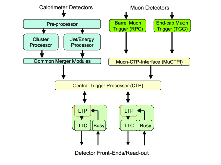
The first-level trigger system of ATLAS (cf. Fig. 1) synchronously processes information from the calorimeter and muon trigger detectors at the heartbeat of the LHC, the proton-proton bunch-crossing frequency of 40.08 MHz. It comprises three sub-systems, the calorimeter trigger, the muon trigger, and the central-trigger system.
2.1 The LVL1 Calorimeter Trigger
The LVL1 calorimeter trigger system receives trigger signals from the calorimeter detectors, that is, the electromagnetic liquid-argon calorimeter and the hadronic scintillator-tile calorimeter. On-detector electronics combine the analogue signals to 7200 trigger towers, which are passed on to the calorimeter-trigger system in the counting rooms next to the ATLAS cavern. The trigger system consists of three subsystems. The PreProcessor receives the trigger-tower signals with a typical granularity of in and . It digitises the analogue signals, assigns a proton-proton bunch crossing to the trigger pulses that extend over multiple bunch crossings, and does a final lookup-table based calibration in transverse energy before sending digital data to the next two calorimeter subsystems: the algorithmic trigger processors. The Cluster Processor identifies and counts isolated electron/photon and hadron/tau lepton candidates. The transverse energy of the electron/photon (hadron/tau) candidates is discriminated against up to 16 (8) programmable thresholds. The Jet/Energy-sum Processor identifies jet candidates and discriminates them against 8 programmable thresholds. It also calculates missing and total transverse energy of the whole event. Common-Merger Modules carry out merging before sending the data for each of the trigger objects multiplicity and threshold information to the central-trigger system synchronously with the 40 MHz machine. Upon reception of a LVL1-accept signal (L1A) the data are sent to the readout system and the LVL2 trigger.
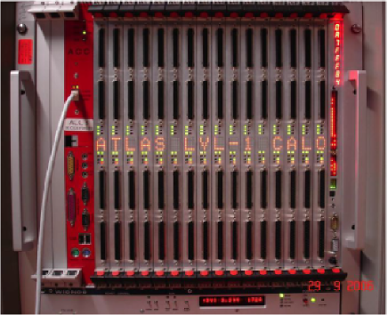
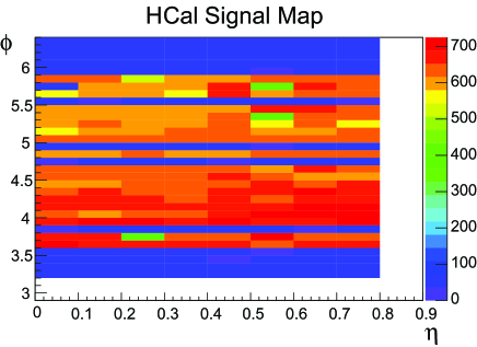
The installation of the calorimeter-trigger system at the ATLAS experimental site is proceeding well. Pre-production boards of the three main components, the PreProcessor (cf. Fig. 2), the Jet/Energy-sum Processor, and the Cluster Processor, are available and tested. The production of the final boards is well advanced and expected to be finished by the end of March 2007. The analogue trigger cables connecting the calorimeter front-end electronics with the off-detector calorimeter-trigger electronics are all produced and tested, about 80% are also installed and connected. First connection tests with the central-trigger system were successful. Integration with the calorimeters has started and is proceeding in parallel to the commissioning of the trigger boards. Figure 3 shows a result from these integration tests with the calorimeters. Using of the barrel hadronic calorimeter, the connection was tested recording calibration signals at the PreProcessor level. As can be seen from the map shown in the figure, a reasonable signal was recorded from almost all of the connected channels. One suspicious channel, at , which was connected but saw no signal, is under investigation. The connectivity tests proved also to be useful to learn about signal shapes and noise levels.
2.2 The LVL1 Muon Trigger
The ATLAS muon spectrometer consists of muon chambers for precision measurements and dedicated fast muon detectors for providing information about muon candidates to the LVL1 Central Trigger. The trigger chambers are resistive-plate chambers (RPCs) in the barrel region and thin-gap chambers (TGCs) for the end-caps . The trigger detectors in both the barrel and the end-caps are sub-divided in and space into trigger sectors. In total there are 64 sectors for the barrel and 144 sectors for the end-caps, the typical RoI size is .
The on-detector trigger electronics receives as input the pattern of hits in the trigger chambers from more than channels. Coincidences in different trigger stations are identified independently in and , based on geometrical roads whose width is related to a programmable transverse-momentum threshold making use of the deflection of muons in the magnetic field. The coincidence allows six transverse momentum thresholds to be used at the same time. Moreover, a proton-proton bunch crossing is assigned to muon-candidate tracks. In the off-detector part of the muon trigger, the Sector Logic, which is situated in the counting rooms next to the ATLAS cavern, combines the trigger data into muon candidates per trigger sector. For each clock cycle, the muon trigger system sends the muon candidate multiplicities per sector for each of the six transverse-momentum thresholds to the central trigger.
The installation of the LVL1 muon trigger chambers is in full swing. The production of the final on-detector electronics is almost finished:
-
•
For the RPCs, all of the on-detector components are installed. The barrel part of the muon spectrometer comprising the chambers, the readout electronics and the services, entered the commissioning phase and will be fully operational by November 2007. Pre-production versions of the off-detector parts of the LVL1 muon barrel trigger are already available and being used in integration tests. Production of the final boards is expected to commence in spring 2007.
-
•
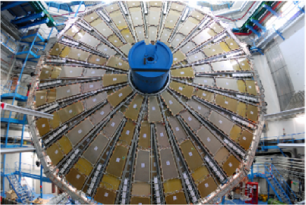
For the TGCs, the chambers and on-detector electronics are available and await installation in the ATLAS cavern. The end-cap part of the muon spectrometer is organised in eight big wheels, each of which is 25 m in diameter. Six of the wheels are composed of trigger chambers, while the other two are made of the precision readout chambers (which are Monitored Drift Tubes). Currently (February 2007), the first big TGC wheel is installed in the cavern, cf. Fig. 4, the second one is being assembled. Pre-production versions of the Sector-Logic boards are available and have been tested, mass production is about to commence (March 2007). Further integration activities, especially with the central-trigger system, have not yet begun but are planned for Spring 2007.
2.3 The LVL1 Central Trigger
The LVL1 Central Trigger is composed of the central-trigger processor (CTP) and the Muon-to-CTP-Interface (MuCTPI). The MuCTPI receives muon candidate information from the barrel and end-cap muon trigger chambers and resolves cases where a candidate traverses a region with overlapping trigger sectors to avoid double counting. It forms muon multiplicities for the six configurable transverse-momentum thresholds and sends these data to the CTP as trigger input. The CTP then derives the LVL1 trigger decision based on the information received from the calorimeter and muon trigger systems according to a programmable trigger menu which aims at selecting high-transverse-momentum leptons, photons and jets, as well as large missing and total transverse energy. The CTP also applies prescale factors and dead time and distributes the LVL1 accept (L1A) signal to the various sub-detectors to initiate data readout. Busy signals from sub-detectors are propagated to the CTP allowing to throttle the generation of L1As. For accepted events the CTP and MuCTPI send data to the readout system as well as to the LVL2 trigger.
A demonstrator of the MuCTPI and the final CTP system are already installed in the underground counting room next to the ATLAS cavern. The current MuCTPI provides almost the full functionality of the final system, missing only some flexibility in the handling of overlaps between muon trigger sectors. One sector input board out of 16 is currently available, corresponding to one octant of one half of the detector. It provides inputs for 14 out of 208 trigger sectors. The final boards are expected to become available for integration in the experiment mid 2007. The CTP crate is already equipped with the final boards. Both the CTP and MuCTPI are frequently used in integration and commissioning activities at the ATLAS site.
3 ATLAS Commissioning and Integration Activities
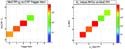
Various combined cosmic-ray runs including different sub-detectors of ATLAS were performed since August 2006. For some of these test runs, temporary gas systems were operational for one sector of the muon barrel detector [3], comprising six precision readout chambers (Monitored Drift Tubes) and six RPC trigger towers. The on-detector coincidence boards were connected to one off-detector sector-logic board which determined muon candidates per transverse-momentum threshold and sent them to the central trigger. The central trigger in turn was configured to trigger on any muon candidate and provided the L1A that initiated the readout of the sub-detectors. The data was used for validation in all involved sub-systems. Figure 5 shows correlation plots of data that was transmitted from the LVL1 muon-trigger electronic to the MuCTPI, and from the MuCTPI to the CTP. On the left-hand side, we plot the trigger item fired on the CTP versus the transverse-momentum threshold at the MuCTPI, on the right-hand side the candidate’s momentum threshold from the RPC data versus the MuCTPI data. As desired, there is an exact one-to-one correlation in both plots demonstrating the data integrity.
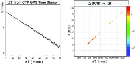
The left-hand side of Fig. 6 shows the distribution of time differences between consecutive events, determined from the CTP time stamp. As expected, the events are exponentially distributed. The right-hand side of Fig. 6 verifies the correct functioning of the GPS-time-stamp assignment to each event. The plot shows the correlation between the difference in the bunch-crossing identifier (BCID) of consecutive events and the GPS-time difference of these events. As expected from the fixed bunch-crossing frequency (of 40 MHz), there is a one-to-one correlation between the two quantities. One can also see that there are no events closer together than 20 bunch crossings, which is expected from the dead-time settings in the CTP for this particular run (for every L1A the CTP introduced a dead-time of 20 bunch crossings).
An ATLAS-wide effort to establish regular cosmic-ray data taking activities to integrate step by step the whole of ATLAS towards first collisions at the end of 2007 was started in December 2006. Cosmic rays were recorded with parts of the barrel hadronic and electromagnetic calorimeters. The CTP provided a common clock and distributed the L1As to initiate the detector readout. The next campaign beginning in March 2007 will include besides the barrel calorimeters also parts of the barrel muon detectors.
Another important milestone for the trigger system of ATLAS was reached in February 2007 with the successful integration of a full muon trigger slice up to LVL2. A LVL2 trigger algorithm was run for the first time in real online mode during a cosmic-ray run. One sector of the LVL1 muon barrel trigger was operated together with MuCTPI and CTP, which provided RoI data to the LVL2 farm. A trigger algorithm was run that selected downward-going muon candidates. The algorithm was seeded by the LVL1 RoI data and requested in turn sub-detector data from the readout system to reconstruct a muon candidate track. The algorithm was found to run as expected, reconstructing muon candidates with a mean processing time of 1 millisecond, well within the LVL2 time budget of 10 milliseconds.
4 Conclusions
The installation and integration of the ATLAS LVL1 trigger system is now in full swing. The final modules are mostly already produced and are being installed in the experiment as they become available. Parts of the system, especially one sector of the muon-barrel trigger and the central-trigger system, are frequently operated in test runs in combination with other ATLAS sub-detectors like the barrel calorimeters. These cosmic-ray data are used for system validation and data integrity checks. On the LVL1 trigger side, integration of the calorimeter-trigger system and the end-cap muon trigger system with the central trigger are expected to commence in spring 2007.
References
- [1] The ATLAS Collaboration, “First-level Trigger Technical Design Report”, CERN/LHCC/98-14, 1998.
- [2] The ATLAS Collaboration, “High-level Trigger, Data Acquisition and Controls, Technical Design Report”, CERN/LHCC/2003-022, 2003.
- [3] Chiodini et al., “RPC Cosmic-Ray Tests in the ATLAS Experiment”, these proceedings.