Tunability of wire-grid metamaterial immersed into nematic liquid crystal
Abstract
We propose electrically tunable hybrid metamaterial consisting of special wire grid immersed into nematic liquid crystal. The plasma-like permittivity of the structure can be substantially varied due to switching of the liquid crystal alignment by external voltages applied to the wires. Depending on the scale of the structure, the effect is available for both microwave and optical frequency ranges.
Electromagnetic properties of periodic arrays of metal wires, stripes and finely structured particles have attracted increasing attention in recent years. The variety of emerging phenomena extends from the negative refraction and subwavelength light constraining Pendry2000 to extraordinary transmission Ebbesen , which all have been attributed to regular metallic structures with periods smaller or much smaller than the wavelength of electromagnetic radiation. As a rule, the unusual properties are characterized by a considerable or even anomalously strong frequency dispersion. Undoubtedly, this opens prospective possibilities for tuning and switching, since a small modification of the system may result in a substantial change of its electromagnetic response at a given signal frequency.
Liquid crystals (LC) inherently have all the necessary characteristics to provide tunability to subwavelength metal arrays. By switching the orientation of LC medium between metal elements or in metal cavities one can trigger substantial changes in the overall properties. Importantly, LCs are transparent and significantly anisotropic in both microwave and optical frequency ranges, in which subwavelength metal arrays are usually operating deJeu ; Sambles . Finally, the metal constituents can be readily used as electrodes for applying switching voltages.
In the past decade, various types of metamaterials have received significant attention due to negative values of permeability and permittivity (see e.g. the recent reviews shalaev ; linden and refs. therein). Certain methods are known how to provide tunability to metamaterials at microwave frequencies by inserting electronic semiconductor components lapin ; zharov ; padilla . However, it still remains challenging to achieve this at optical frequencies. In this Letter we describe how nematic LC environment can provide tunability to the plasma frequency of wire-grid metamaterial.
Wire lattices exhibit plasma-like permittivity for electromagnetic radiation with wavelengths much larger than the lattice period Pendry ; Belov . In particular, for electromagnetic waves traveling normally to the grid of infinite parallel wires and polarized along them (-plane of incidence and -polarization of electric field in Fig. 1), the employed component of the effective local permittivity is
| (1) |
Here is the -component of the permittivity tensor of host medium surrounding the wires, and the parameter is determined by the grid geometry.
The so-called plasma-frequency, at which the permittivity (1) changes its sign, is . The grid on its own is transparent at frequencies higher than and reflecting at lower frequencies. Being accompanied by a 3D array of split-ring resonators providing negative permeability, the structure is a transparent left handed medium for and reflects waves with .
The presence of in Eq. (1) suggests an easy way of tuning the metamaterial by varying the host medium permittivity. Nematic LCs provide a natural opportunity to realize this. Anisotropic LC permittivity axes follow the orientation of the director :
| (2) |
Typically, elongated molecules of nematic LC tend to align along interfaces due to surface anchoring. The resulting LC alignment along the wires is shown in Fig.1 on the left.
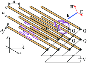
If external voltages are applied to the neighboring wires, this will load them with charges of different signs. The arising static electric field in the -plane will force the LC molecules to orient perpendicularly to the wires as shown in Fig.1 on the right. As a result, switches from to providing the relative switching range of
| (3) |
The dielectric anisotropy of LC is known to be at least of the order of several dozens of percent for both microwaves and light deJeu ; Sambles . Therefore, the proposed design provides a possibility of shifting the plasma-frequency by 10–20%.
Let us find out the voltage to be applied to the grid for efficient switching. Consider the quadratic lattice of cylindrical wires as shown in Fig. 1. Assume that a voltage applied across the nearest neighbors loads the wires with charge per length densities . The charges are distributed over the surfaces of thin wires. We neglect the angular inhomogeneity of this distribution and assume the electric field of a wire to be the same as that of a charged wire axis. We also presume that the static dielectric anisotropy of the nematic is small and the electric field pattern is not perturbed by the inhomogeneously oriented LC.
A single wire stretched along the line and loaded with the charge per unit length produces the electric field potential , where , is the static permittivity of the LC, and the zero of the potential is assigned to the wire surface. In the infinite 2D lattice of alternatingly charged wires, the total potential outside of the wires is
| (4) |
where and the coordinate origin lies on the axis of a positively charged wire.
We have calculated (4) for finite latices. In spite of the absence of true mathematical convergence of the series, the potential distribution establishes already for a lattice of wires. Further increase of the number of wires does not affect the potential in the middle provided that the overall electric neutrality is preserved.
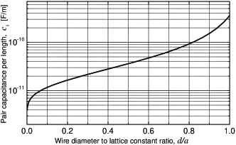
Applied voltage equals the difference of the potential on positively and negatively charged wires, . The capacitance per length of a grid of large even number of wires is . It is convenient to introduce the capacitance per pair of wires in the vacuum per length, , which naturally appears in the relation . Apparently, is a function of two geometric parameters, and , and depends on their ratio . The calculated values of are presented in Fig. 2. Note that tends to infinity at instead of , when the neighboring wire surfaces come in contact. This is the consequence of neglecting the anisotropy of the charge distribution over wire surface. We see that even for thick wires our approximation is reasonably good.
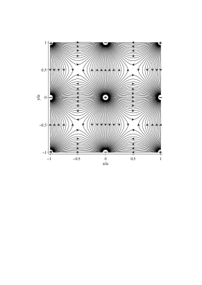
Typical calculated electric field pattern is shown in Fig. 3. The field amplitude is maximum at the wire surfaces (where the lines are condensed) and vanishes at the middle points of the diagonal lines connecting the nearest wires with the same sign of charge.
Now we consider the effect of this field on the nematic. If we totally neglect the LC elasticity, the anisotropic molecules should align along the field lines. The director then lies strictly in the -plane and the switching is perfect. The finite elasticity of the LC disturbs the ideal picture and the bending pattern of the director differs from the field lines pattern. However, this is of minor importance for the switching since the director still stays within the -plane.
The critical effect of LC elasticity occurs in the vicinity of the wires. To ensure the LC orientation along the wires when the voltage is switched off, the anchoring of LC molecules at wire surfaces must be strong. When the voltage is switched on, the anchoring still forces the molecules at the surfaces to point along the -axis. Accordingly, the director has to rotate by an angle of within the transient layer from the wire surface to the LC bulk. Efficient switching occurs when this layer is thin compared to the scale of the structure (lattice constant), i.e., practically important is the limit of strong electric field and thin transient layer.
In this limit, we can neglect the contributions from other wires to the field near a wire surface. In the cylindrical coordinates, the only present -component of the electric field equals while the nematic director has two components and . At the wire surface .
The free energy of the LC can be presented as the sum of the elastic deformation energy and the dielectric energy deJeu , where the latter reads
| (5) |
Here the upper limit is large enough to assure and can be extended to infinity. The simplest form of the LC elastic energy is given by the so-called one constant approximation:
| (6) |
Introducing the director polar angle as , we obtain the compact form of the total energy
| (7) |
where the parameter characterizes relative contribution of the voltage-driven term.
Minimizing the functional (7) yields the differential equation for :
| (8) |
with the boundary conditions and . For the exact solution reads:
| (9) |
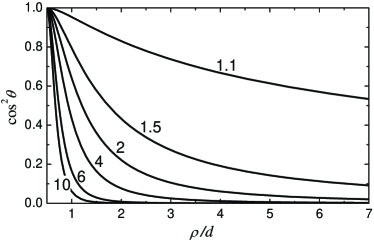
The spatial variation of the -component of dielectric tensor (2), is controlled by the factor . The profiles of the latter are given in Fig. 4 for several values of larger than unity. It is seen that the voltage has to exceed considerably the critical value to provide the LC reorientation within thin transient layer. For the layer thickness becomes comparable with the wire diameter. For estimates, we take a nematic LC elastic modulus N, static permittivity and static dielectric anisotropy . We also set the wire diameter to be ten times smaller than the lattice constant, which according to Fig. 2 yields F/m. Then appropriate voltage is estimated as
| (10) |
Remarkably, this moderate voltage is independent of the scale of the grid.
One notes that the studied LC switching geometry differs qualitatively from the conventional one within flat electrooptic cells. In our case, the LC bulk is directly aligned and reoriented by the immersed wires. We believe this to be an additional advantage for microwave applications, where the controlling of millimeter (or even centimeter) thick LC samples by cell surfaces is practically impossible.
In summary, we have demonstrated that the plasma frequency of wire-grid metamaterial immersed into nematic LC can be efficiently tuned by 10-20% due to the switching of LC alignment. Our estimates show that the necessary voltage applied to the wires is of the order of several Volts. The main conclusions are valid for both microwave and optical frequency ranges.
References
- (1) J.B. Pendry, Phys. Rev. Lett. 85, 3966 (2000).
- (2) W.L. Barnes, A. Dereux, and T.W. Ebbesen, Nature 424, 824 (2003).
- (3) W.H. de Jeu, Physical Properties of Liquid Crystalline Materials, Gordon and Breach, London, 1980.
- (4) J.R. Sambles, R.Kelly, and F. Yang, Phil. Trans. R. Soc. A 364, 2733 (2006).
- (5) V.M. Shalaev, Nature Photonics, 1, 41 (2007).
- (6) S. Linden, C. Enkrich, G. Dolling et al., IEEE J. of Selected Topics in Quant,. Electr., 12, 1097 (2006).
- (7) M. Lapine, M. Gorkunov, and K.H. Ringhofer, Phys. Rev. E 67, 065601(R) (2003).
- (8) A.A. Zharov, I.V. Shadrivov, and Yu.S. Kivshar, Phys. Rev. Lett. 91, 037401 (2003).
- (9) H.-T. Chen, W.J. Padilla, J.M.O. Zide, et al., Nature 444, 597 (2006).
- (10) J.B. Pendry, A.J. Holden, W.J. Stewart, and I. Youngs, Phys.Rev. Lett. 76, 4773 (1996).
- (11) P.A. Belov, R. Marques, S. I. Maslovski et al., Phys. Rev. B 67 113103 (2003).