[width=height=3.1cm]empty2w \titlefigurecaptionThis is the figure caption. \maile-mail arzhnikov@otf.pti.udm.ru, Phone +07-3412-218988, Fax +07-3412-250614 11institutetext: Physical-Technical Institute, Ural Branch of Russian Academy of Sciences, Kirov str. 132, Izhevsk 426001, Russia \publishedXXXX
Structural peculiarities of plastically-deformed cementite and their influence on magnetic characteristics and Mossbauer parameters
Abstract
Cementite Fe3C is studied with first-principles calculations. Two possible positions of carbon atoms in the iron sublattice are considered: with prismatic or octahedral environment. Mossbauer spectra (MS) with parameters calculated for both modifications are simulated above and below the Curie temperature. A possibility to detect the change in carbon position upon annealing from MS is discussed. It is shown that this is hardly possible using a standard approach to treatment of MS, but it can be seen in more subtle details of the MS below the Curie temperature, such as widths and positions of separate lines.
pacs:
75.50.Bb, 75.60.Cn, 71.15.ApThe properties of cementite, i.e. iron carbide , are being studied for a long time. Originally, cementite was investigated in order to improve the mechanical properties of steels. Its magnetic properties have received some attention in connection with nondestructive methods of the steel control. A recent interest in the properties is aroused by new possibilities of obtaining metastable compounds by mechanical alloying, implantation and so forth (see, for example, [1, 2, 3, 4]). An additional impact has been given by the studies dealing with the chemical composition of the Earth’s core [5, 6]. Besides, the monophase by itself has attracted considerable interest due to some peculiarities in the bulk-modulus behaviour [7] and the instability of the magnetic state under pressure [8, 9].
The structure of cementite is believed to be known well from the experiments on the X-ray diffraction, for example, [10]. But many magnetic, Mossbauer and EELS experimental data [11, 12, 13], conducted for non-equilibrium samples, lead us to think that its structure varies depending on the mechanical and thermal treatment. As these variations are not detected by the X-ray diffraction, one can suppose that there are cementite modifications differing in the carbon positions, which do not noticeably affect the X-ray diffraction patterns because of the large difference in the scattering factors between iron and carbon. The neutron diffraction experiments conducted recently on the well-annealed samples [14] showed that carbon atoms occupy the prismatic positions. So, after annealing at high temperatures (above 700 K [10, 14, 11]) cementite is in the ground state and has a sole, well-determined, structure. The structure of the non-equilibrium cementite comes into question.
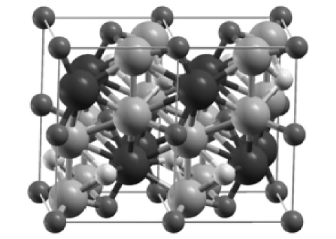
According to the structural considerations in [15], carbon can occupy four positions between the iron sites, that are called prismatic and octahedral, and distorted prismatic and octahedral. The carbon in the two last positions is closer to iron atoms and these modifications appear to be improbable. Fig. 1 displays the structure of cementite, with two possible carbon positions shown together.
In this work, first-principles calculations have been conducted for cementite with different positions of carbon in the lattice. Earlier in [16], using such calculations, we have received that the prismatic modification of cementite has a smallest energy and is its ground state, and explained an unusual behavior of the coercive force in the mechanically alloyed cementite on the annealing temperature as a transition of cementite from octahedral modification with small magneto-crystalline energy to the prismatic one with large . At the same time, we do not know unambiguous direct experiments demonstrating existence of the octahedral modification of cementite. The X-ray diffraction experiments do not show the carbon position with a necessary accuracy, and the neutron powder diffraction experiments have been done for well-annealed samples being in the ground state without traces of metastable phases. So, the aim of the paper is to calculate and compare the parameters of hyperfine interaction of cementite with different position of carbon atoms, to simulate the Mossbauer spectra (MS) and to estimate the possibility of experimental detection of the octahedral modification of cementite with the help of the Mossbauer spectroscopy.
Some theoretical investigations of cementite have been already carried out (see, for example, [6, 8, 17, 18]). Only in [17] an attempt to obtain and compare some characteristics of the prismatic and octahedral cementite modifications has been done, but no analysis on experimental detection has been conducted.
The crystal structure of is an orthorhombic lattice, we use the Pbnm space group. The unit cell contains 12 iron atoms and 4 carbon atoms (a double unit cell, drawn with the help of the package [19] in Fig. 1, shows carbon positions in both prismatic and octahedral environment).
The calculations presented in this paper have been conducted by the full-potential linearized augmented plane wave (FLAPW) method in the WIEN2k package [20]. The generalized gradient approximation of the exchange-correlation potential (GGA) [21] is used in this work. The details of the calculational procedure can be seen in [16]. Calculated are the Fe atomic magnetic moments, hyperfine magnetic fields (HFF), isomer shifts (IS), the electric field gradient (EFG) at the Fe nuclei. and are the maximum- and the minimum-in-magnitude components of the tensor of the EFG; ; and are the polar and azimuthal angles of the HFF in the local coordinate system of the EFG. Using the parameters calculated, we have simulated the Mossbauer spectra for polycrystals (which is usually characteristic of cementite) with the help of the program described in [22].
Table 1 gives data (cell parameters, magnetic moments, Mossbauer parameters) for each system.
| prismatic | octahedral | |||
| a, b, c | 0.4490, 0.5047, 0.6743 | 0.4711, 0.5111, 0.6960 | ||
| number | Fe I, | Fe II, | Fe I, | Fe II, |
| of atoms | 4 atoms | 8 atoms | 4 atoms | 8 atoms |
| 1.97 | 1.91 | 2.09 | 1.90 | |
| 0.05 | 0.04 | 0.05 | 0.03 | |
| -25.1 | -24.7 | -24.3 | -23.7 | |
| 3.1 | 2.7 | 3.1 | 1.9 | |
| -22.0 | -22.0 | -21.2 | -21.8 | |
| IS | 0.16 | 0.17 | 0.22 | 0.14 |
| 3.07 | 1.37 | 1.99 | -2.09 | |
| 0.05 | 0.83 | 0.996 | 0.23 | |
| 90 | 138.6 | 90 | 73.1 | |
| 0 | 11.2 | 90 | 26.6 | |
A difference between the magnetic moments in the prismatic and octahedral cementite is found numerically small, so magnetic measurements are not expected to determine which carbon position is realized in samples.


A difference in the EFG between the two modifications draws attention. One could expect that this difference should manifest itself in the MS above the Curie temperature. The simulation of the spectra with zero hyperfine field and other parameters from Table 1 (see Fig. 2) shows, however, that practically no difference can be seen between the two modifications. This occurs because the difference wears off due to summation of two subspectra from nonequivalent positions Fe I and Fe II.
Below the Curie temperature (see Fig. 3), the spectra can be distinguished better, as the difference becomes clearer in the outermost lines. The subspectra are essentially affected by the combined hyperfine magnetic and quadrupole interaction. The summary spectra cannot be also decomposed at a glance, but some traces of a combined interaction still exist and manifest themselves in the distances between the peaks of the simulated MS (see Table 2). We remind that in the absence of the quadrupole interaction the distances between the first and second lines and the fifth and sixth lines in the Mossbauer sextet are equal.
| prismatic | octahedral | |||||
|---|---|---|---|---|---|---|
| Fe I | Fe II | summary | Fe I | Fe II | summary | |
| 1.71 | 1.43 | 1.52 | 1.43 | 1.33 | 1.38 | |
| 1.21 | 1.52 | 1.50 | 1.43 | 1.64 | 1.57 | |
In an actual non-equilibrium sample, an even more complicated case should be realized, as there should be a mixture of the modifications, and only a scrupulous mathematical processing of spectra with a preliminary model of the relations between the HF parameters obtained theoretically for two modifications can give a necessary evidence of the octahedral modification.
The quadrupole splitting above the Curie temperature and its absence below have been also observed earlier in experiments of [23]. The parameter of quadrupole splitting measured above in [23] corresponds to our calculation (see [16]). However, the authors supposed that the disappearance of the quadrupole interaction in the spectrum below is a result of a special angle between EFG and HFF (55 degree). Our calculations show that this is not true for all positions of iron atoms and for both modifications (see Table 1). As the MS simulation shows, the presence of a large quadrupole interaction is concealed under the Curie temperature by superposition of few subspectra.
Observing the change in the carbon position upon annealing the plastically-deformed cementite is hardly possible using standard simple approaches to the MS. A first sign of existence of the octahedral modification in samples and its disappearance with annealing is a change of the width of lines in the MS and of the relative distances between lines (compare the MS’s marked as 3 in Fig. 3).
So, to construct an initial model of the local atomic structure for a mathematical processing of MS, a simple approach does not serve: it is not possible to finally receive an adequate fit of the MS. A correct description can be obtained using the results of first-principles calculations. Certainly, one must bear in mind that first-principles calculations do not give very accurate magnitude of hyperfine parameters and give correctly the tendencies in their behavior and the relations between different sites.
The authors are grateful to professor V. Rusakov for helpful discussions. This work was partially supported by RFBR (grant 07-03-96011).
References
- [1] E. P. Elsukov, G. A. Dorofeev, V. M. Fomin, G. N. Konygin, A. V. Zagainov, and A. N. Maratkanova, Phys. Met. Metallogr. 94, 356 (2002).
- [2] R. C. Reed and J. H. Root, Scr. Mater., 38, 95 (1998).
- [3] A. Koniger, C. Hammerl, M. Zeitler, and B. Rauschenbach, Phys.Rev.B 55, 8143 (1997).
- [4] M. Umemotoa, Z. G. Liu, K. Masuyamab, and K. Tsuchiyaa, Scr.Mater. 45, 391 (2001).
- [5] B. J. Wood, Earth Planet.Sci.Lett. 117, 593 (1993).
- [6] L. Vocadlo, J. Brodholt, D. P. Dobson, K. S. Knight, W. G. Marshall, G. David Price, and I. G. Wood, Earth Planet.Sci.Lett. 203, 567 (2002).
- [7] E. Duman, M. Acet, T. Hulser, E. F. Wassermann, B. Rellinghaus, J. P. Itil, and P. Munsch, J. Appl. Phys. 96, 5668 (2004).
- [8] J.-F. Lin, V. V. Struzhkin, H. Mao, R. J. Hemley, P. Chow, M. Y. Hu, and J. Li, Phys. Rev. B 70, 212405 (2004).
- [9] E. Duman, M. Acet, E. F. Wassermann, J. P. Itie, F. Baudelet, O. Mathon, and S. Pascarelli, Phys.Rev.Lett. 94, 075502 (2005).
- [10] E. J. Fasiska and G. A. Jeffrey, Acta Cryst. 19, 463 (1965).
- [11] E. P. Yelsukov, A. I. Ul’yanov, A. V. Zagainov, and N. B. Arsent’yeva, JMMM 258-259, 513 (2003).
- [12] A. N. Maratkanova, Y. V. Ruts, D. V. Surnin, A. N. Deev, V. M. Schastlivtsev, I. L. Yakovleva, T. I. Tabatchikova, S. A. Gusev, and N. N. Salashchenko, Phys. Met. Metallogr. 89 N 6, 604 (2000).
- [13] E. P. Elsukov, V. M. Fomin, D. A. Vytovtov, G. A. Dorofeev, A. V. Zagainov, N. B. Arsent’eva, and S. F. Lomaeva, Phys. Met. Metallogr. 100, N 3, 251 (2005).
- [14] I. G. Wood, L. Vocadlo, K. S. Knight, D. P. Dobson, W. G. Marshall, G. D. Price, and J. Brodholt, J. Appl. Cryst., 37, 82 (2004).
- [15] V. M. Schastlivtsev, I. L. Yakovleva, D. A. Mirzaev, and K. Yu. Okishev, Phys. Met. Metallogr. 96, 313 (2003).
- [16] A. K. Arzhnikov, L. V. Dobysheva, and C. Demangeat, J.Phys.: Cond.Mat. 19, 196214 (2007).
- [17] I. N. Medvedeva, L. E. Kar’kina, and A. L. Ivanovskii, Phys. Met. Metallogr. 96, 452 (2003).
- [18] J. Haglund, G. Grimvall , and T. Jarlborg, Phys. Rev. B. 44, 2914 (1991).
- [19] A. Kokalj, J. Mol. Graphics Modelling 17, 176 (1999).
- [20] P. Blaha, K. Schwarz, G. K. H. Madsen, D. Kvasnicka and J. Luitz, WIEN2k, An Augmented Plane Wave + Local Orbitals Program for Calculating Crystal Properties (Karlheinz Schwarz, Techn. Universitat Wien, Austria), 2001. ISBN 3-9501031-1-2.
- [21] J. P. Perdew, S. Burke, and M. Ernzerhof, Phys. Rev. Lett. 77, 3865 (1996).
- [22] R. N. Kuzmin (ed.), Practice of the Mossbauer effect (Moscow State University, Moscow, 1987), 160 p. (in Russian).
- [23] M. Ron and Z. Mathalone, Phys.Rev.B 4, 774 (1971).