Experimental position-time entanglement with degenerate single photons
Abstract
We report an experiment in which two-photon interference occurs between degenerate single photons that never meet. The two photons travel in opposite directions through our fibre-optic interferometer and interference occurs when the photons reach two different, spatially separated, 2-by-2 couplers at the same time. We show that this experiment is analogous to the conventional Franson-type entanglement experiment where the photons are entangled in position and time. We measure wavefunction overlaps for the two photons as high as 94 3%.
pacs:
78.67.-n, 85.35.DsI INTRODUCTION
The fact that the mathematical model of quantum mechanics suggests an object can exist in a superposition state, for instance in two different places at the same time, is one of the most surprising realisations people have when first learning quantum mechanics. The fact that a number of different particles can exist in a superposition-state is the logical extension made by Einstein, Podolski and Rosen (EPR) EPR and then Greenberger, Horne and Zeilinger GHZ . Often the EPR experiment is explained to students as if the two particles are entangled at the point of emission, usually in the polarization-basis. However, it can be shown that two separate single particles which are certainly not entangled at the point of emission, but are identical, can also display entanglement if an appropriate experiment is designed which post-selects events where they cannot be distinguished. Here we interfere two single photons from a single-photon-source using only a Mach-Zehnder interferometer (MZI), in which the photons actually travel in opposite directions and interfere on separate couplers, at different times.
II EXPERIMENTAL ARRANGEMENT
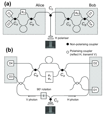
The experiment, similar to that proposed by Franson Franson , is shown schematically in Fig.1(a). The experiment is set up so that the two indistinguishable photons emitted by the source have a time separation which is equal to the difference in the delays induced by each arm in each MZI, , where is the refractive index, and the lengths of the long and short arms in Alice’s MZI. is an order of magnitude longer than the coherence time of the photons and thus no second-order interference can occur when the paths are recombined Brendel ; Kwiat . The only way a coincidence can occur is if the first photon takes the long path and is delayed by relative to the second photon, taking the short path. In this case, it will not be possible for two detectors in Alice’s interferometer (D1 and D2) to distinguish the events where both photons arrive at the detectors at the same time: either both were reflected at coupler , or both were transmitted. If the coupler has equal reflection and transmission coefficients fourth-order interference ensures these two events cancel out and no coincident detection events for D1 and D2. This two photon interference effect requires only that is approximately equal to to within the length of the photon wavepacket. In other words, the observation of fourth order interference does not require a fixed phase relationship between each pair of photons or wavelength-scale stability of , and so is independent of the phase . A similar requirement is needed to observe two-photon interference at Bob’s end of the apparatus. Quantum-dot single-photon sources that can lead to this two-photon interference effect have now been reported by several groups SantoriNature ; BennettOptExp2 ; Varoutsis . Already a number of experiments have used this effect to implement simple quantum protocols such as teleportation Fattal1 and polarization entanglement generation Fattal2 . It is sometimes argued that this interference effect, widely studied with photons, is due to their bosonic nature and results from the photons sticking together when they collide at the coupler . However, there is no interaction between photons. The Franson entanglement experiment shows that in actual fact the photons can interfere even if they are incident on separate couplers, such that they are never in the same place at the same time. Considering detectors it can be shown that the probability of a coincidence, is given by:
| (1a) | |||
| (1b) | |||
| (1c) | |||
| (1d) | |||
where, for clarity, we have assumed a perfect single photon source with and perfect spatial overlap of the two input modes at each coupler. The wave-function overlap of the two photons is . From equation [1], we see that if coincidences will only occur for detectors arranged symmetrically about the experiment and in Fig1(a), whereas anti-symmetric detector pairs, and , will not detect coincidences. In this way, it appears that post-selected events where Alice and Bob receive one photon each are entangled in position and time. If the opposite is true. As the positions of the two photons are uncertain until the time at which the measurements are made this scheme offers a useful way of distributing entanglement between remote parties. This scheme is particularly well suited to a demonstration in optical fibres as it is robust against decoherence occurring in the long fibre lengths between coupler and the MZIs. A number of cryptographic schemes have been demonstrated based on this idea using parametric down-conversion sources Tittel . One difference we would like to stress is that in previous works with non-linear crystals both photons are created simultaneously, with a fixed phase relationship. Thus interference occurs when each photon takes the same paths in either interferometer (either long-long or short-short). However, in our experiment the two photons are created at different times and have no fixed phase relationship. Thus only fourth order interference occurs when the photons take opposite paths in the two MZIs.
Note that any variation in that is much less than the photon coherence time does not affect the results of these correlations. However, to observe this effect it is necessary to stabilize to be fixed for each measurement and to be able to control this quantity on a sub-radian scale. Variations in room temperature, air flow and mechanical stress will disrupt the MZIs and lead to a loss of entanglement.
The matching of to , and also to , could be achieved using variable delay lines in each MZI but these components typically induce a sizable photon loss. Although, wavelength-scale stability can be achieved with active stabilization and some feedback system ZYOptExp we have opted to perform the experiment in a modified interferometer where any shifts in phase occur equally to both MZIs simultaneously. This interferometer is shown in Fig. 1(b). In our interferometer the two photons are once again split at coupler and travel in opposite directions. However, now the leftward traveling photon has its polarization changed from H to V. The two photons are then fed into opposite sides of a single MZI where they travel through in opposite directions. As both photons have orthogonal polarization a polarization-dependent phase shift can be applied in one arm of the interferometer, to provide the required control of the phase shift analogous to in Fig. 1(a). In our experiment any drift then occurs equally in both the leftward and rightward traveling photons. The logic behind our labeling of the couplers and in Fig. 1(a) is now clear. If it is assumed that there is a negligible polarization dependence to and , we can predict the visibilities of interference that may be expected between detector pairs, , from equations [1]. Although this is an approximation we have confirmed experimentally that there is a significantly larger difference between and values for a given coupler than between the two values for different polarizations.
| (2a) | |||
| (2b) | |||
| (2c) | |||
| (2d) | |||
Interestingly, due to our symmetric choice of couplers as defined above we see that is limited only by the wave-function overlap of the two photons, .
III RESULTS
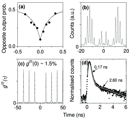
We now discuss our experimental results. Our single-photon-source is a pillar microcavity containing a single quantum dot with exciton () emission at 943.2nm, coincident with the cavity mode. The cavity was photolithographically defined to have a nominal diameter of 1.75 m, and contained 17 (25) periods in the Bragg mirror above (below) the one-wavelength thick cavity. Processing is carried out with standard photolithography and a reactive ion etch to produce cavities with =4500. During the experiment the sample is held in a continuous flow cryostat at 3.6K and optically excited at to the normal with a ps-pulsed tuneable laser optimised to excite a resonance in the photoluminescence-excitation spectrum of the state, at 908.85nm. The excitation density was chosen to be more than one order of magnitude below the level required to saturate emission from the state so as to minimize dephasing and temporal jitter associated with occupation of the biexciton state BennettOptExp2 . Care is taken to ensure that the excitation density is constant throughout the experiment. Photons are collected with a NA = 0.5 microscope objective on axis with the pillar. The source delivers photons with a high multi-photon suppression ratio ( = 1.5%, Fig. 2(c)) which are close to the time-bandwidth limit BennettOptExp2 . We note that for this source bunching of photons in adjacent pulses is negligible. The emission is then spectrally filtered by a monochromator and the single photons coupled into our fibre optic interferometer.
Monitoring correlations between detectors on the same side of the interferometer, say detectors , the temporal overlap of the two photons on is optimized by varying the time delay between the two laser pulses used to excite the source. A Hong-Ou-Mandel dip is observed with a visibility of 80% (Fig, 2(a)).
Using a 4-channel timer card we record correlations between 4-pairs of detectors ( and ) simultaneously. For each pair we normalize the data to the total number of coincidence events occurring on that channel within 16 ns of time zero, excluding the central 0.6 ns. This procedure removes any effect due to varying singles-count rates on each detector pair (due to unequal detection efficiencies) and also any effect due to varying count rates between measurements at each setting of (which occurs due to small changes in the coupling of photons into the optic fibres). After this normalization procedure every peak at a given time delay has the same area in each correlation. An example is shown in Fig. 4(a) for channel 1,3 for maximally constructive and destructive interference. For each channel we then define as the integrated area within a 0.6 ns-wide window centered on time zero for this normalized data. We chose a 0.6ns time window as this encompasses the central peak area whilst minimizing the contribution of the flat background we observe in the correlation (the origin of which will be discussed later). All are then normalized by the same constant, so as to ensure the mean value , calculated from all measured settings of , is unity. The results of this data set are shown in Fig. 3 for each of the four pairs of detectors. Least squares fits to the functions stated in equation 1 are shown as solid lines and from these the visibilities of the interference, are calculated (see Fig. 3). As expected the highest visibility of interference is observed on detectors .
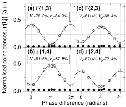
We note that because we have unequal reflection and transmission coefficients in our couplers the average count rate observed on each channel differs (shown as a dotted horizontal line in Fig. 3). On average it is higher for both the anti-symmetric pairs, and the visibilities are lower for both of these pairs. From fits to the measured data we have confirmed that for each setting of within errors. This observation can only be made because our definition of is independent of the degree of correlation on other channels for that particular setting of . An alternative method of analysis would have been to define the sum of the counts in central 0.6ns for all channels at each setting of to be unity.
IV FACTORS LIMITING THE VISIBILITY
The experiment was repeated with three separate quantum dots located on the same semiconductor chip. In all cases visibilities in excess of 55% have been observed, suggesting that more than half of all post-selected photon pairs are entangled. For simplicity we have only presented data from one of these photon sources here but we have noted that for all these QDs there is a clear tail to the photoluminescence excited from the sample. Shown in Fig.2(d) is a time-resolved photoluminescence trace data recorded from the photon source recorded under the same excitation conditions. An excellent fit to this data can be made using two exponential functions: a fast component which occurs promptly after the excitation pulse (measured decay time of 170 ps, limited by our APD time resolution) and a longer lived component with a decay time of 2.60 ns. Such long-lived components in the emission from a single QD have been observed before Smith ; Schwab and are usually attributed to the population of dark-states or charge states in the QD that store carriers for a time before repopulating the state. Such delayed photons are obviously not time-bandwidth limited and can in fact lead to small number of false coincidences at time zero.
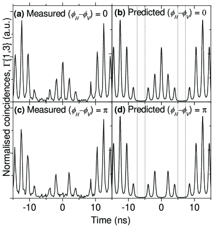
To estimate the number of false counts we might expect at time zero from this tail we have used the raw data to reconstruct the correlations we may expect between a pair of detectors if the visibility were 100%. This was achieved by convolving the experimental time-resolved data in Fig.2(d) with itself to obtain the shape of the peaks expected in the autocorrelation. This peak shape provides an excellent fit to the peak-shapes in Fig. 2(b) and (c). Multiple peaks, scaled correctly and offset from time-zero are then used to construct the expected correlations. Finally, the effect of dark counts was added into each plot. The resulting fits are shown in Fig. 4 for both the cases where (Fig. 4(b)) and (Fig. 4(d)), which show good agreement with the corresponding experimental data from (1,3), shown in Fig. 4(a) and (c). Our purpose in showing the modeled data is to illustrate that the long lived component of the emission results in a number of false counts in the central 0.6 ns window which is identical to the constant level of false counts observed between 5.0 and 7.5 ns (and similar time-windows spaced at the 12.5ns repetition period). The presence of the long-lived component to the state emission thereby degrades the visibility of the interference. Therefore, from the raw correlation data for each channel we have obtained a direct indication of the contribution to counts at time zero for every dataset. The results of this analysis are shown in Fig.3 as filled-data points on each plot. Subtracting the effect of these false counts we are able to obtain a more accurate measure of the visibility of interference, , which is stated for each channel in Fig.3. The visibilities observed from each detector pair are now either greater than, or within error equal to, the 71% value required prove non-locality Franson . As predicted by equation 2, the correlation observed between displays the highest visibility at 84 3 %.
We also expect that the finite value of will add to false counts at time zero. Using the formula quoted for the area of the central peak by Santori SantoriNature it is possible to calculate the overlap of the wavefunctions of the two photons, where is the probability that the source emits more than one photon as a result of either one of the excitation pulses occurring in each 12.5 ns cycle. In the limit where the excitation level is well below saturation, as it is here, we assume that . Thus we are able to infer a wavefunction overlap, , of 94 3%. The remaining effect reducing this value from 100 % is the temporal distinguishability of the photons emitted from the source.
V CONCLUSION
To conclude, we have used a single photon source to generate photons entangled in position and time. Passive matching of time delays and phase shifts are achieved by passing the two photons through the same interferometer in different directions, with different polarizations. The degree of wave-function overlap for the two photons is as high as 94 3 % suggesting that with further improvements these sources may be of use for quantum information applications, such as entanglement distribution between remote stations or as ancilla photon sources in photonic quantum computing.
This work was partly supported by the EU through the IST FP6 Integrated Project Qubit Applications (QAP: contract number 015848) and Network of Excellence SANDiE.
References
- (1) A. Einstein, B. Podolsky, and N. Rosen, Phys. Rev. 47, 777 (1935).
- (2) D. M. Greenberger, M. A. Horne, and A. Zeilinger, in Bell’s Theorem, Quantum Theory, and Conceptions of the Universe, edited by M. Kafatos (Kluwer Academics, Dordrecht, The Netherlands) 72 (1989).
- (3) J. Franson, Phys. Rev. Lett. 62, 2205 (1989).
- (4) J. Brendel, E. Mohler and W. Martienssen, EuroPhys. Lett. 20, 575 (1992).
- (5) P. G. Kwiat, A. M. Steinberg and R. Y. Chiao, Phys. Rev. A 47, R2472 (1993).
- (6) C. Santori, D. Fattal, J. Vukovi , G. S. Solomon and Y. Yamamoto, Nature 419, 594 (2002).
- (7) A. J. Bennett, D. C. Unitt, A. J. Shields, P. Atkinson, and D. A. Ritchie, Opt. Exp. 13, 7772 (2005).
- (8) S. Varoutsis, S. Laurent, P. Kramper, A. Lemaître , I. Sagnes, I. Robert-Philip, and I. Abram, Phys. Rev. B 72, 041303 (2005).
- (9) D. Fattal, E. Diamanti, K. Inoue, and Y. Yamamoto, Phys. Rev. Lett. 92, 037904 (2004).
- (10) D. Fattal, K. Inoue, J. Vukovi , C. Santori, G. S. Solomon, and Y.Yamamoto, Phys. Rev. Lett. 92, 037903 (2004).
- (11) W. Tittel, J. Brendel, H. Zbinden and N. Gisin , Phys. Rev. Lett. 84, 4737 (2000).
- (12) Z. Yuan and A. Shields, Opt. Exp. 13, 660 (2005).
- (13) J. M. Smith,P. A. Dalgarno, R. J. Warburton, A. O. Govorov, K. Karrai, B. D. Gerardot, and P. M. Petroff, Phys. Rev. Lett. 94, 197402 (2005).
- (14) M. Schwab, H. Kurtze, T. Auer, T. Berstermann, M. Bayer, J. Wiersig, N. Baer, C. Gies, F. Jahnke, J. P. Reithmaier A. Forchel, M. Benyoucef and P. Michler, Phys. Rev. B 74, 045323 (2006).