UPDATE ON ION STUDIES111This work is supported by the Commission of the European Communities under the 6th Framework Programme ”Structuring the European Research Area”, contract number RIDS-011899.
Abstract
The effect of ions has received one of the highest priorities in R&D for the damping rings of the International Linear Collider (ILC). It is detrimental to the performance of the electron damping ring. In this note, an update concerning the ion studies for the ILC damping ring is given. We investigate the gap role and irregular fill pattern in the ring. The ion density reduction in different fills is calculated analytically. Simulation results are presented.
1 Introduction
Ions are recognized as a potential current limitation in storage rings with negatively charged particle beams [1]. The ions mainly come from beam-gas collisions. In some circumstances, they are trapped in the potential well of the beam. They couple to the motion of the beam and lead to adverse effects such as beam emittance growth, betatron tune shift and spread, collective instabilities and beam lifetime reductions [2].
There are two kinds of ion effects in electron storage rings. One is the conventional ion trapping which occurs when the circulating beam traps ions after multiple turns. It can be cured by introducing a few successive empty RF bucket (gaps), which are long compared to the inter-bunch spacing. In this case, the ions are strongly focused by the passing electron bunches in the beginning and then over focused in the gap. With a sufficiently large gap, the ions can be driven to large amplitudes, where they form a diffuse halo and do not affect the beam. However, in high current storage rings or linacs with long bunch trains, the ion accumulation during the passage of a single bunch train may cause a transient instability which is called fast ion instability (FII) [3, 4]. For the electron damping ring of the ILC, the bunch intensity is large and the bunch spacing is small and the fast ion instability is potentially striking [5]. Since the vertical beam emittance is much smaller (2 pm) than the horizontal one (0.5 nm), the FII is much more serious in the vertical plane.
In this note, the linear theory of ion effect is briefly recalled in section 2. In section 3, the gap effect in the fill is studied and the ion density reduction due to mini-trains in different fill patterns is investigated analytically. Section 4 shows the simulation results of FII for mini-trains. A short summary is given in the end.
2 Linear theory of ion effects
Without gaps in the fill, the ions with a relative molecular mass greater than A will be trapped in the beam potential, where,
| (1) |
here, denotes the number of particles per bunch, the classical radius of proton, the bunch spacing, the horizontal and vertical beam size, respectively. It can be seen that the minimum trapped mass is closely related to the beam size. By using the beam parameters of three typical fill patterns in the ILC damping ring, from case A to case C as shown in Table 1 [6], the minimum trapped mass along the ring for two fill pattern case A and C is shown in Figure 1 and Figure 2 respectively. The number of bunches decreases from A to C while the particles per bunch increase to maintain a comparable overall charge. Here we take one sextant of the ring as an example.
Beam parameters Fill pattern Case A Case B Case C Number of bunches 5782 4346 2767 Particles per bunch [1010] 0.97 1.29 2.02 Bunch spacing [bucket] 2 2 4 Number of trains 118 82 61 Bunches per train f2 0 0 23 Gaps between trains g2 0 0 28 Bunches per train f1 49 53 22 Gaps between trains g1 25 71 28 FII char. growth time at train end [10-9 s] 3.922 4.527 4.030 FII expo. growth time with 30% ion freq. spread [10-6 s] 6.889 6.892 6.913 Coherent tune shift at train end 0.325 0.325 0.324
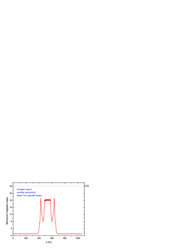

It can be seen that for the fill pattern case A, all the CO ions will be trapped in the beam along the ring. While for the fill pattern case C, the CO ions can not be trapped in some parts of the ring.
The linear theory [3, 4] gives characteristic growth rate of FII which strongly depends on the bunch intensity, number of bunches, transverse beam size and the residual gas pressure. It can be estimated as
| (2) |
where is the residual gas pressure, is the bunch number, and are the classical radius of electron and proton respectively, is the speed of light, is the relativistic gamma factor, is the atomic mass number of the residual gas molecules and is the vertical betatron frequency. The ion coherent oscillation frequency is given by
| (3) |
However, the ion motion becomes decoherent because the vertical ion frequency depends on the horizontal position. Furthermore, the existence of various ion species and the variation of the beam size along the ring also introduce a spread in the ion oscillation frequency. Taking into account the ion coherent frequency spread, the linear theory gives the coupled bunch motion in the bunch train rising as , and in this case the exponential growth rate is given by
| (4) |
where denotes the rms spread of the ion coherent frequency as the function of the azimuthal position around the ring. the bunch train length. For the baseline design of the ILC damping ring, simulation shows the spread of ion coherent frequency to be about 30% [7].
If the ions are trapped in the beam potential, they give rise to additional focusing to the beam. The ion induced coherent tune shift is given by
| (5) |
here C is the circumference of ring, is the vertical beta function, is the ion line density, is the ionization cross section (1.86 Mbarn and 0.31 Mbarn for carbon monoxide and hydrogen ions, respectively at beam energy of 5 GeV). k is Boltzmann constant and T is the temperature. By using beam parameters of the ILC baseline damping ring [8], the FII characteristic growth time, exponential growth time with 30% ion coherent frequency spread and ion induced coherent tune shift at bunch train end for a single long bunch train case are analytically estimated in Table 1. A CO partial pressure of 1 nTorr is assumed here. It can be seen that the growth time is extremely fast for the case of one long train. Even with 30% ion frequency spread, the FII growth time is still faster than one revolution period . The ion induced tune shift is large at a gas pressure of 1 nTorr for CO, so a lower vacuum gas pressure is critical to alleviate FII effect.
3 Gap effect in the fill
In the previous section, one long bunch train has been assumed and the ions are trapped by the bunch train. The trapping condition is disturbed when the fill pattern consists of a number of short bunch trains (mini-trains) with gaps in between. In the following, we will analyze the gap effect and ion density in different fill patterns.
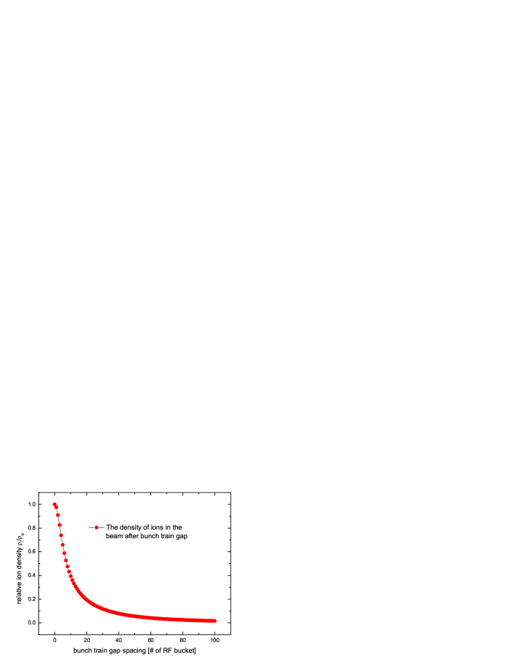
The ions inside the beam are defined as those ions within of the beam centroid. Note that the growth rate of FII is proportional to the ion density [9]. The diffusion of the ions during the gaps increases the size of ion cloud and therefore reduces the ion density. With a gap introduced in the bunch train, one can estimate the density of the ions in the beam after the clearing gap as [2]
| (6) |
where is the ion density at the end of the one bunch train, is the gap length between two adjacent bunch trains, are the ion oscillation frequencies as follows
| (7) |
For the ILC damping ring, the harmonic number h = 14516, the circumference C = 6695.057 m. We made an analytic estimation of the relative ion density reduction versus train gap spacing. The result is shown in Figure 3. It can be seen that the relative ion density diminishes with respect to the bunch train gap spacing. If the gap length is larger than 30 RF bucket, the ion density is about 10% of the initial ion density. Beyond 30 RF bucket, the ion density no longer changes significantly. Taking into account the transient beam loading effect, train gap should not be too long. For current ILC damping ring fill patterns, the length of train gap varies from 25 to 71 RF bucket. Meanwhile, in order to evaluate the effect of the gaps, an Ion-density Reduction Factor (IRF) is defined as [9]
| (8) |
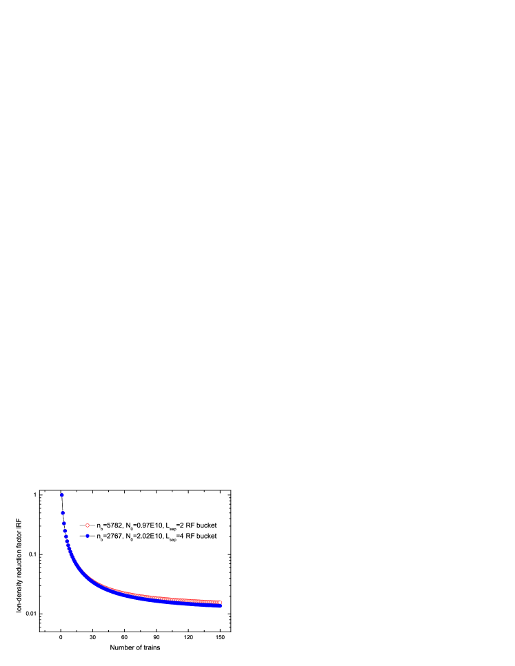
where is the number of trains, is the diffusion time of the ion cloud which can be estimate from Eq.(3). IRF is the ratio of the ion density with gaps and without gaps. In one long bunch train case, the ring is completely filled and the ions can accumulate indefinitely. With a fixed gap, a larger number of shorter bunch train helps to keep the ion density low. However, for a fixed ring circumference and total number of bunches, the length of gap shrinks as the number of bunch trains increases. The optimum fill pattern depends on the diffusion time, the circumference, and number of bunches. Figure 4 shows the IRF versus number of trains in OCS6 damping ring for fill pattern case A and C respectively. It can be seen here if the harmonic number and ring circumference are fixed, the IRF reduces with respect to the number of trains. Beyond 60 trains the IRF does not change a lot.
The beam parameters of the ILC damping ring are listed in Table 2.4-1 of Ref. [8]. There are 5 different fills in this ring. For different fill patterns, the total number of particles is kept constant so that the specified luminosity can be achieved.
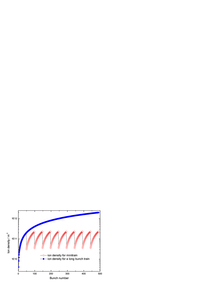
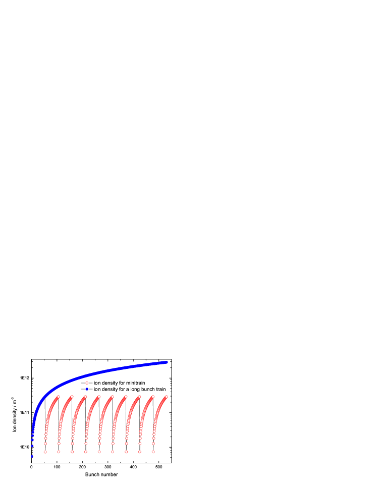
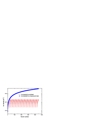
The ion density for different fill patterns case A, B and C are shown in Figure 5, Figure 6 and Figure 7 respectively for ten bunch trains. The CO partial pressure is 1.0 nTorr. It can be seen that the ion density for a single long bunch train will increase linearly with respect to the bunch number. However, if the gaps are introduced between the adjacent bunch trains, the ion density is reduced significantly. It also indicates that the ion density for mini-trains can quickly reach the peak value after the first few bunch trains. For the fill patterns A, B and C, the mini-trains can reduce the ion density by about two orders of magnitudes comparing to a single long bunch train. Since the growth rate of FII is proportional to the ion density, it indicates that the growth rate of FII can be reduced by a factor of 100. In this case, the FII can be potentially damped by a fast feedback system.
4 Simulation study of FII in the ILC damping ring
A weak-strong code is used to simulate the FII in the ILC electron damping ring [10]. The effect of mini-trains is taken into account. Figure 8 shows the growth of the vertical oscillation amplitude versus number of turns for a single long bunch train and for mini-trains of fill pattern A. The bunch is recorded here.
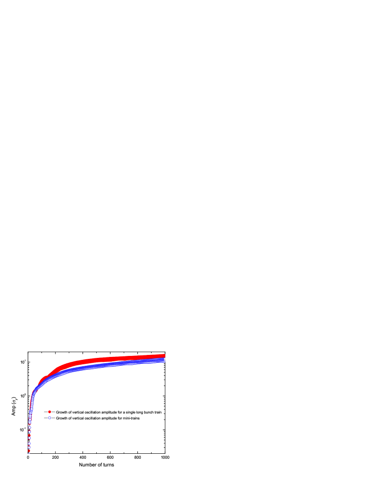
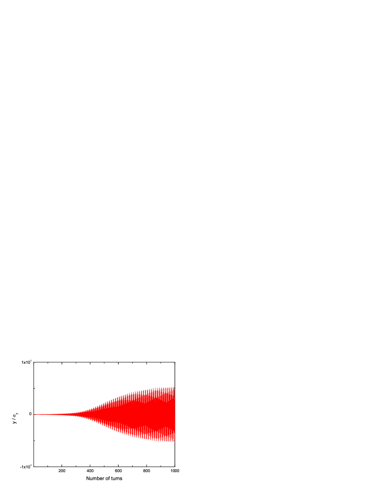
It can be seen when the gap is introduced in the bunch trains, the growth of vertical oscillation slows down. This is because in the case the ion density for mini-trains is less than that of a single long bunch train case in Figure 5. Figure 9 shows the bunch centroid oscillation versus number of turns in the fill pattern case A. The bunch is recorded here. We can see the bunch centroid begins to oscillate with small amplitude and then reaches the saturation after about 600 turns [11]. This is also one of the characteristics of the FII.
5 Conclusion
Gaps between bunch trains can significantly reduce the ion density in the ILC damping ring; a gap exceeding 30 RF bucket reduces the ion density by a factor 10. Depending on fill pattern the ion density diminishes by about two orders of magnitude compared to one long bunch train case. Simulation shows the growth of vertical oscillation amplitude to be attenuated with gaps in the fill.
References
-
[1]
Slides:
http://ilcagenda.linearcollider.org/contributionDisplay.py?contribId=334&sessionId=65&confId=1296 - [2] J.M. Byrd et al., SLAC-PUB-7389 (1996).
- [3] T. Raubenheimer and F. Zimmermann, Phys. Rev. E 5 5487 (1995).
- [4] G.V. Stupakov, T. Raubenheimer and F. Zimmermann, Phys. Rev. E 5 5499 (1995).
- [5] A. Wolski et al., LBNL-59449 (2006).
- [6] M. Kuriki, et al., ILC-Asia-2006-03 (2006).
- [7] L. Wang, talks at ILCDR07 Workshop in Frascati, (2007).
- [8] G. Aarons, et al., ILC-Report-2007-01 (2007).
- [9] L. Wang, et al., SLAC-PUB-12643 (2007).
- [10] G. Xia, et al., Proceedings of EPAC06, MOPLS133, Edinburgh, UK (2006).
- [11] G. Xia, et al., Proceedings of PAC07, THPMN016, Albuquerque, New Mexico, USA (2007).