The Time Response of Glass Resistive Plate Chambers to Heavily Ionizing Particles
Abstract
The HARP system of resistive plate chambers (RPCs) was designed to perform particle identification by the measurement of the difference in the time-of-flight of different particles. In previous papers an apparent discrepancy was shown between the response of the RPCs to minimum ionizing pions and heavily ionizing protons. Using the kinematics of elastic scattering off a hydrogen target a controlled beam of low momentum recoil protons was directed onto the RPC chambers. With this method the trajectory and momentum, and hence the time-of-flight of the protons can be precisely predicted without need for a measurement of momentum of the protons. It is demonstrated that the measurement of the time-of-arrival of particles by the thin gas-gap glass RPC system of the HARP experiment depends on the primary ionization deposited by the particle in the detector.
keywords:
Gaseous detectors, detectors, particle identification methods, timing detectors1 Introduction
The HARP experiment [1], [2] has been designed to measure hadron production cross-sections on nuclear targets with a precision of a few percent over almost the full solid angle. A set of solid and liquid targets spanning a large range in atomic number was exposed to beams of protons and pions with momenta between 1.5 and 15 . The elements used ranged from hydrogen to lead. HARP took 450 million physics triggers, collected data for about 300 different settings and recorded 30 TB of information from August 2001 to October 2002.
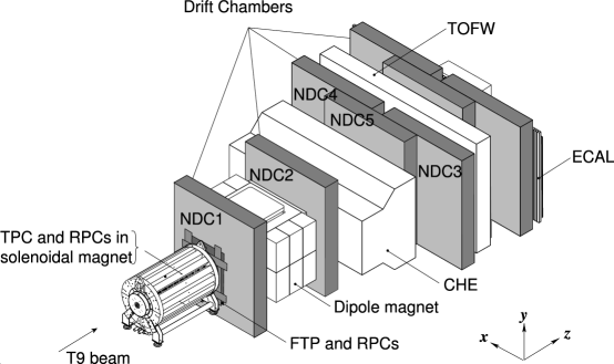
The setup of the HARP experiment is shown in figure 1. A detailed description of the detector and its performance is given in Ref. [1], [2]. The spectrometer can be subdivided into three main systems. Beam and trigger detectors provide tracking and identification of beam particles, and trigger decisions. Forward detectors provide tracking, momentum measurement and identification of secondary particles at angles less than with respect to the beam axis. Large angle detectors deal with tracking, momentum measurement and particle identification at large production angles.
The large angle detector system consists of Time Projection Chamber (TPC), Resistive Plate Chambers (RPC) and an Inner Trigger Cylinder (ITC).
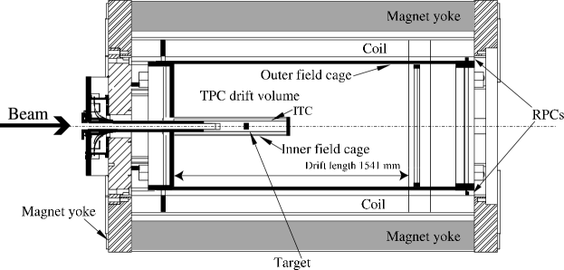
The TPC has a cylindrical form with a length of 200 cm and a diameter of 83 cm. It is located inside a solenoid magnet producing a 0.7 T field. It measures momentum, trajectory and ionization energy losses of particles emitted from the target at large angles () with respect to the incoming beam. The RPCs are arranged in the shape of a barrel around the outer field cage of the TPC. A target station and the ITC are situated inside TPC volume, in a truncated inner field cage (see figure 2).
This paper concentrates on a specific effect found when calibrating the time response of the HARP RPCs. Besides the well-known time-walk correction, their time response was found to depend on the primary ionization deposited in the gas gap. Brief information needed to understand the RPC hardware and calibration procedures is given in the next section. The evidence for the effect itself is given in the Section 3, followed by some discussion (Section 4) and conclusions (Section 5).
2 HARP RPC system
Particle identification (PID) at large angles is mainly performed by mean energy loss () measurements in the TPC. A complementary system for particle identification to distinguish between electrons and pions in the momentum range 125 –250 is needed. For these relatively low momenta PID can be performed by time-of-flight (ToF) measurements. A time resolution of 200 ps is required when particles traverse the TPC over the shortest distance ( 400 mm). ToF measurements with such a resolution also help in pion–proton separation up to 1 . A system of resistive plate chambers has been designed and used as additional PID device for particles emerging with large production angles.
The RPCs are constructed as a four-gap stack of glass plates. The gap size is precisely set to 0.3 mm by interposing a fishing line (nylon mono-filament) with suitable diameter between the plates. The stack consists of two identical structures of three glass plates each, arranged symmetrically on both sides of a central readout electrode. The glass plates are 0.7 mm thick and made of standard float glass with a specific resistivity of cm. A view of the cross-section through the short side of the glass stack is shown in figure 3. The negative high voltage is applied to the glass plates by means of a coated graphite layer with resistivity of 200 on the two outer glass plates of both sets. A single readout electrode, located in the center of the glass stack, collects signals from all four gaps. It is segmented into 64 rectangular strips. Eight strips are connected to one pre-amplifier forming a readout channel. Thus, each chamber has eight readout channels, in the following referred to as pads, and numbered from 1 to 8 starting from the most upstream one. Pads with one and the same number define a pad-ring. A chamber is 1920 mm long, 104 mm wide and 7.8 mm thick. Each chamber is housed in an aluminum box with dimensions 2 m 150 mm 10 mm.

Thirty such chambers are arranged around the TPC in two staggered layers forming a barrel. They cover polar angles from to with respect to the beam axis and in azimuthal angle with a small 13 mm overlap between the layers. The set of two layers fits into a 25 mm radial space between the TPC and the coils of the solenoid magnet. The readout electrodes of the inner and outer layer are located at radial distances of 421 mm and 434.5 mm, respectively. The front-end electronics of each channel consists of a pre-amplifier board mounted on the chamber and a combined splitter/discriminator module.
Pre-amplifiers are based on the AD8009 chip operating with an amplification factor of 30. The amplified signals are transmitted through mini coaxial cables over a distance of 0.8 m – 2.5 m (depending on the channel in question) to a passive patch panel and from there over a distance of 5 m through Lemo 50 cables to a custom-made splitter and leading edge discriminator module. Each signal is amplified once more there (with a factor 3 using the same AD8009 chip) and split into two separate signals. One of them is discriminated (the discriminator threshold is put at 5 mV) and is sent via a 80 m twisted pair cable to a Time–to–Digital Converter (TDC), model CAEN V775 with a channel nominal width of 35 ps. The other signal is sent through another 80 m twisted pair cable to a Charge–To–Digital Converter (QDC), model CAEN V792.
The RPCs were operated in avalanche mode at a voltage of kV between outer and central electrodes and with a gas mixture of 90% , 5% , and 5% .
Typical random noise rates were in the range of 200 Hz–300 Hz per chamber, i.e. 1 kHz/m2, which is an acceptable level compared to the typical particle rate 10 kHz/m2 over the area covered by the barrel RPC.
A precise calibration of the RPC sub-detector is needed before it can be used for time-of-flight measurements. The aim of the calibration is to develop a procedure that transforms data read out from a TDC channel into a flight-time of particles from the production point in the target to the RPC pad feeding that particular TDC channel. An in-situ calibration procedure has been developed [5] by using reconstructed charged particle tracks in the TPC from interactions produced by beams of positive particles with momenta of 3 , 5 , and 8 bombarding 0.05 (nuclear interaction length) thick Ta, Pb, Sn and Cu targets. Pion tracks were selected by using measurement in the TPC. The algorithm converts the TDC scale into physical units, accounts for the arrival time of the beam particle at the target, for the transit time of the signal within the pad and from the pad to the preamplifier, and for temperature fluctuations of the time response. It also corrects for so called time-walk arising from the fact that signals with different pulse-height and the same shape cross the fixed discriminator level at different time. It is worth mentioning that the calibration procedure corrects for threshold crossing delays under the assumption of a single, universal pulse-shape of the signals from all particles. The correction is quite large, up to 2 ns and is of the order of the smallest time-of-flight to be measured.
3 RPC time response
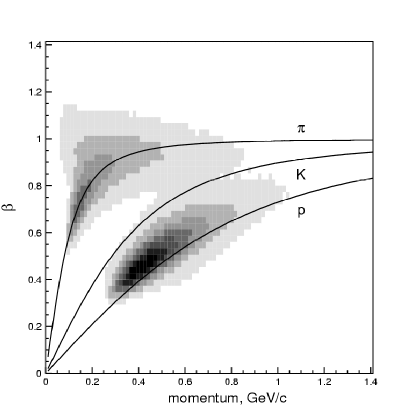
Figure 4 demonstrates the correlation between measured relativistic velocity of positively charged particles and their momentum measured in the TPC when the time-walk is calibrated with pion signals and applied to all tracks [5]. It is clearly seen that proton signals are shifted with respect to the theoretical curve. The rest of this section is devoted to the understanding of the origin of this shift.
In Ref. [9] two mechanisms were suggested which could be the cause of this effect. One possible explanation is the fluctuation in arrival time of the first cluster of the primary ionization. This fluctuation is smaller for heavily ionizing particles. The other possibility is a change of pulse shape near threshold due to a possibly different ionization and different gas amplification regime.
Since the observed rise-time of the signal to the discriminator threshold is several ns, a small difference in signal shape between heavily ionizing particles (protons with momenta between 250 and 800 in our case) and minimum ionizing particles (here pions with momenta above 150 ) could induce such an effect. Effects below a ns are contained within the expected avalanche formation time.
Dedicated analyses have been performed to understand the effect better.
First, we compared the relative time offset between the measured over-threshold time of the signal and the predicted arrival time of protons above 1 with relativistic pions and with heavily ionizing protons as a function of the measured energy loss of particles in the TPC gas (Figure 5). To reduce the possible effect of the time-walk correction we use a total pulse charge range in terms of channel counts, which is a region of relatively high pulse charge where still a large statistics can be obtained. The energy loss in the TPC gas is correlated with the ionization density of the same particle crossing the RPC gas gaps, just shifted by the material between the TPC gas volume and the RPC gas gaps. Figure 5 shows a clear dependence of the time offset on the ionization density. The points where both pions and protons are minimum ionizing show a similar time offset, while the points at higher display a trend justifying our hypothesis.

This result came as first evidence that a dependence on the ionization density in the gas gaps plays a role [9].
Further, if our hypothesis is correct, the time difference between the observed signal (corrected for the time–walk per pad) and the expected arrival time calculated on the basis of the track length and particle momentum as measured in the TPC should show a dependence as a function of momentum for the same set of pad-rings due to the correlation between the energy loss and momentum for a given particle species 111It is important to distinguish between different pad-rings because particles emerging from the target cross the pad-rings at different inclinations, hence they produce different total ionization even having the same momentum.. Such a dependence was suggested in Ref. [5] and the respective plots are reproduced here in figure 6. The behavior seen in the figure indeed demonstrates a clear dependence on ionization density () and a dependence on different path lengths at fixed only for low values of this quantity.


It should be noted that the above momentum dependencies were obtained using the momentum of the particles measured in the TPC gas. In Ref. [10], [11] it has been pointed out that a similar behavior can be obtained when a systematic shift in the measurement of momentum is present. Besides our confidence, based on various independent calibration methods, that our momentum measurement is unbiased ([2], [9], [12], [13]) the effect of any momentum measurement bias in the TPC can be eliminated by an analysis employing the kinematics of elastic scattering using a liquid hydrogen target. Such a measurement makes it possible to send a “controlled beam” of slow protons through the TPC and towards the RPC system without the need to measure the momentum of the recoil proton with the TPC. The prediction for the momentum and direction of the recoil proton can be obtained from the kinematics of the event by measuring the scattering angle of the forward scattered proton or pion. Exploiting this, we have used an exposure of the HARP detector where a 5 beam of protons and pions is directed onto a 60 mm long liquid hydrogen target. Elastic events are selected from the total sample of triggers requiring one and only one track in the forward spectrometer, and exactly one track in the TPC. The momentum of the track measured in the forward dipole spectrometer is required to be consistent with elastic scattering hypothesis. Only events with exactly one RPC hit are retained. The position of the RPC hit has to be consistent with the predicted impact point of the recoil track, using the direction of the forward scattered track to define the trajectory of the recoil particle. This selection of elastic scattering events has a purity of 99% [12]. Due to the acceptance of the forward spectrometer, the distribution of selected recoil protons peaks at with respect to the beam direction, thus almost perpendicular to the RPC chambers, with most of the tracks contained between and . The recoil momenta are between 350 and 600 . The geometry of the RPC system is such that the large majority of selected recoil protons traverses pad-ring 3, therefore, this measurement is performed using this pad-ring only. In order to predict the time-of-flight of the particle reliably, the initial momentum and energy loss in the material traversed has to be described accurately. For example, a proton with 325 momentum in the TPC gas has lost in terms of momentum on average 45 with an r.m.s. of 15 in the material between the interaction point and the TPC gas volume and is going to lose 83 more (with an r.m.s. of 25 ) in the outer field cage before reaching the RPC detection volume. At 575 the total reduction in momentum is 38 on average with similar r.m.s.222The general HARP Monte Carlo simulation package (see [2]) based on GEANT4 toolkit [14] has been used throughout the analysis presented in this article.
The properties of the kinematics of elastic scattering are used to predict the path-length of the particle from the interaction point to the RPC detector and the time-of-flight over this distance. Monte Carlo simulation is used to verify that the predicted and reconstructed time and path-length agree within 5 ps and 2 mm, respectively. In the left panel of figure 7 the time difference, defined as the measured time minus the predicted time, is displayed as a function of the predicted momentum of the proton in the gas of the TPC. The momentum was predicted using the kinematics of elastic scattering. The fact that the simulated difference of prediction and measurement is consistent with zero shows that the prediction of the flight-time (and thus of the momenta) using the elastic scattering kinematics and Monte Carlo corrections in the reconstruction procedure for respective energy losses is correct. The data exhibits a clear deviation pointing to a difference in RPC time response as a function of the momentum. The right panel of figure 7 shows the same time difference as a function of the momentum predicted at the RPC detection volume. Plots in figure 7 clearly demonstrate the existence of a remarkable dependence of the RPCs response on the primary ionization density produced in the gas-gap by the particles of different types. The magnitude of the effect is in agreement with our previous analysis [2], [5], [9].


In fact, one would expect that the RPC response does not depend directly on momenta of detected particles, but only on their energy deposition in the gap. Given the small range of path lengths in the RPC gas gaps in the sample of elastic events it is natural to show the time differences as a function of total energy deposition in the RPC gas. The energy deposition can be predicted as a function of momentum using our simulation. In figure 8 the same time difference measurements as the ones of figure 7 are displayed as a function of the above energy deposition. The range of this quantity in the data is between two and eight MIP (the average deposition of one minimum ionizing particle). In this limited range a nearly linear behavior of the shift in time response is observed, with the extrapolation to one MIP consistent with a vanishing shift. This is to be expected, since the RPC system was calibrated using pions with momenta close to the value where their energy deposition is minimal. Although the dependence does not show a flattening at higher energy deposition in the measured range, one would expect this to occur at very high ionization losses.

4 Discussion
We have clearly shown in the previous section that the time response of RPCs with thin gas gaps depends on ionization density of detected particles in those gaps even after correction for the usual time-walk based on the total charge of the signal. Evidence for such an effect was reported by us earlier [2], [5], [9], [15]. Now we support our findings by strong additional evidence exploiting proton–proton and pion–proton elastic scattering kinematics that allows us to avoid any dependence on the momentum measurement in the TPC.
In view of the evidence presented in this work, the comments of Ammosov et al. about our first indication [2] of the effect, e.g. [10]:
The timeslewing correction for the timing of pulses with finite rise time has been well understood for over half a century. The discovery that on top of the timeslewing correction a further correction for protons ’due to their higher ionization rate’ is needed, is only one example out of many grave misconceptions and mistakes contained in the above-cited paper. … The above-mentioned discovery that the proton timeslewing correction is different from the pion timeslewing correction by 500 ps is a plain mistake stemming from the lack of understanding of the interplay between TPC track and RPC timing reconstruction.
show that for the authors of [10] such an effect was unexpected and therefore missed.
It is interesting to mention that, after more evidence for the discussed effect was published in our papers [5], [9], the same authors acknowledged the effect without proper reference to our work and tried to construct a physical model explaining it [16]. Their estimation of 80 ps time difference for protons at 400 is by factor of 2.5 smaller than our measurement. In a very recent preprint [17] the same authors exploit the time-of-flight of low momentum protons measured by the same RPC system as a benchmark for their procedure of momentum measurement in the HARP TPC. They do not account for the effect reported here risking a shift in their momentum calibration.
5 Conclusions
It was found that the time response of the thin gap RPC system used in the HARP experiment and calibrated with the assumption of a unique pulse-shape appeared to be different for pions and protons in the momentum range below 1 . In earlier publications we proposed the higher energy loss of protons as a probable explanation of the effect. In this paper it was clearly confirmed that the effect is present and can indeed be understood as originating from the considerably higher ionization produced by the protons in the RPC. Momentum measurement biases in the TPC, if any, have been eliminated as possible cause of the effect.
It should be noted that possible measurement of the effect using a direct beam of protons with momenta as low as 300 –600 would be interesting. However, it is not an easy task due to the high energy losses of such protons.
Acknowledgments
We gratefully acknowledge the help and support of our colleagues from the HARP collaboration M. Apollonio, A. Bagulya, G. Barr, F. Bobisut, M. Bonesini, S. Bunyatov, J. Burguet–Castell, C. Buttar, M. Chizhov, L. Coney, A. De Santo, E. Di Capua, U. Dore, J. Dumarchez, R. Edgecock, M. Ellis, R. Engel, F. Ferri, G. Giannini, D. Gibin, S. Gilardoni, P. Gorbunov, C. Gößling, V. Grichine, P. Gruber, P. Hodgson, L. Howlett, I. Kato, A. Kayis-Topaksu, M. Kirsanov, J. Martín–Albo, G. B. Mills, M.C. Morone, P. Novella, D. Orestano, M. Paganoni, F. Paleari, V. Palladino, I. Papadopoulos, F. Pastore, S. Piperov, N. Polukhina, G. Prior, D. Schmitz, F.J.P. Soler, M. Sorel, A. Tonazzo, L. Tortora, G. Vidal–Sitjes and P. Zucchelli. We are indebted to the PS beam staff and to the numerous technical collaborators who contributed to the detector design, construction, commissioning and operation. In particular, we would like to thank G. Barichello, R. Brocard, K. Burin, V. Carassiti, F. Chignoli, D. Conventi, G. Decreuse, M. Delattre, C. Detraz, A. Domeniconi, M. Dwuznik, F. Evangelisti, B. Friend, A. Iaciofano, I. Krasin, D. Lacroix, J.-C. Legrand, M. Lobello, M. Lollo, J. Loquet, F. Marinilli, J. Mulon, L. Musa, R. Nicholson, A. Pepato, P. Petev, X. Pons, I. Rusinov, M. Scandurra, E. Usenko, and R. van der Vlugt, for their support in the construction of the detector. The authors acknowledge the major contributions and advice of M. Baldo-Ceolin, M.T. Muciaccia and A. Pullia during the construction of the experiment. The authors are indebted to V. Ableev, P. Arce, F. Bergsma, P. Binko, E. Boter, C. Buttar, M. Calvi, M. Campanelli, C. Cavion, A. Chukanov, M. Doucet, D. Düllmann, R. Engel, V. Ermilova, W. Flegel, A. Grant, P. Gruber, Y. Hayato, P. Hodgson, A. Ichikawa, A. Ivantchenko, I. Kato, O. Klimov, T. Kobayashi, A. Krasnoperov, D. Kustov, M. Laveder, M. Mass, H. Meinhard, T. Nakaya, K. Nishikawa, M. Paganoni, F. Paleari, M. Pasquali, J. Pasternak, C. Pattison, M. Placentino, S. Robbins, S. Sadilov, G. Santin, V. Serdiouk, S. Simone, V. Tereshchenko, A. Tornero, S. Troquereau, S. Ueda, A. Valassi, F. Vannucci, R. Veenhof and K. Zuber for their contributions to the experiment and to P. Dini for his contribution to MC production. We acknowledge the contributions of V. Ammosov, G. Chelkov, D. Dedovich, F. Dydak, M. Gostkin, A. Guskov, D. Khartchenko, V. Koreshev, Z. Kroumchtein, L. Linssen, A. De Min, I. Nefedov, A. Semak, J. Wotschack, V. Zaets and A. Zhemchugov to the work described in this paper.
The experiment was made possible by grants from the Institut Interuniversitaire des Sciences Nucléaires and the Interuniversitair Instituut voor Kernwetenschappen (Belgium), Ministerio de Educacion y Ciencia, Grant FPA2003-06921-c02-02 and Generalitat Valenciana, grant GV00-054-1, CERN (Geneva, Switzerland), the German Bundesministerium für Bildung und Forschung (Germany), the Istituto Nazionale di Fisica Nucleare (Italy), INR RAS (Moscow) and the Particle Physics and Astronomy Research Council (UK). We gratefully acknowledge their support. This work was supported in part by the Swiss National Science Foundation and the Swiss Agency for Development and Cooperation in the framework of the programme SCOPES - Scientific co-operation between Eastern Europe and Switzerland.
References
- [1] M.G. Catanesi et al., Proposal to study hadron production for the neutrino factory and for the atmospheric neutrino flux, CERN-SPSC/99-35, Dec. 1999.
- [2] M.G. Catanesi et al., The HARP detector at the CERN PS, Nucl. Instr. Meth. A, 571 (2007), pp. 527-561.
- [3] A. Akindinov et al., A four-gap glass-RPC time-of-flight array with 90 ps time resolution, IEEE Trans. Nucl. Sci., 48 (2001), pp. 1658-1663.
-
[4]
V. Ammosov et al., arXiv:hep-ex/0204022;
V. Ammosov et al., arXiv:hep-ex/0205061. - [5] M. Bogomilov et al., Physics performance of the barrel system of the HARP experiment, IEEE Trans. Nucl. Sci., 54 (2007), pp. 342-353.
- [6] M. Bogomilov et al., The HARP RPC time-of-flight system, Nucl. Instr. Meth. A, 508 (2003), pp. 152-158.
- [7] G. Barr et al., Performance of multigap RPC detectors in the HARP experiment, Nucl. Instr. Meth. A, 533 (2004), pp. 214-220.
- [8] M. Bogomilov, Resistive plate chambers in the HARP experiment, Ph.D. thesis, St. Kliment Ohridski University, Sofia, Bulgaria, (2006).
- [9] M.G. Catanesi et al., Rebuttal of ’Comments to ’The HARP detector at the CERN PS”, Nucl. Instr. Meth. A, 571 (2007), pp. 564-573.
- [10] V. Ammosov et al., Comments on: ’The HARP detector at the CERN PS’ Nucl. Instr. Meth. A, 571, (2007), pp. 562-563.
- [11] V. Ammosov et al., Comments on: ’Physics performance of the barrel system of the HARP experiment’ IEEE Trans. Nucl. Sci., 54 (2007), pp. 1454-5.
- [12] M.G. Catanesi et al., [HARP Collaboration], Measurement of the production of charged pions by protons on a tantalum target, Eur. Phys. J. C51 (2007) 787, arXiv:0706.1600.
- [13] M.G. Catanesi et al., [HARP Collaboration], Momentum scale in the HARP TPC, arXiv:0709.2806 [physics.ins-det]
- [14] S. Agostinelli et al., GEANT4 Collaboration, Nucl. Instr. Meth. A506 (2003), 250.
- [15] M. Bogomilov et al., Rebuttal of Comments on: ’Physics performance of the barrel system of the HARP experiment’ IEEE Trans. Nucl. Sci., 54 (2007), pp. 1455-6.
- [16] V. Ammosov et al., The HARP resistive plate chambers: characteristics and physics performance, Nucl. Instr. Meth. A 578 (2007), pp. 119-138.
- [17] A. Bolshakova et al., The HARP time projection chamber: characteristics and physics performance, CERN-PH-EP/2007-030, 10 August 2007.