Extraordinary surface voltage effect in the invisibility cloak with an active device inside
Abstract
The electromagnetic field solution for a spherical invisibility cloak with an active device inside is established. Extraordinary electric and magnetic surface voltages are induced at the inner boundary of a spherical cloak, which prevent electromagnetic waves from going out. The phase and handness of polarized waves obliquely incident on such boundaries is kept in the reflected waves. The surface voltages due to an electric dipole inside the concealed region are found equal to the auxiliary scalar potentials at the inner boundary, which consequently gain physical counterparts in this case.
pacs:
41.20.Jb, 42.25.FxPendry et al. Pendry et al. (2006) firstly proposed the invisibility cloak based on coordinate transforms where a “hole” is created in the transformed coordinate system and an object in the “hole” can be concealed from detection. Another method was reported to produce similar effects in the geometric limit Leonhardt (2006). Designs of invisibility cloaks based on other methods have also been published Greenleaf et al. (2007); Alu and Engheta (2005); Milton and Nicorovici (2006); Sihvola (2006). From the viewpoint of transformation method Pendry et al. (2006), the hole creation does not result in an electromagnetic vacuum but rather a complete separation of electromagnetic domains into a cloaked region and those outside Pendry et al. (2006); Sheng (2006). More precisely, a “true” cloak should not only cloak passive objects from incoming waves, but also cloak active devices by preventing waves from going out and being detected. The effectiveness of a transformation based cloak design for hiding a passive object was first confirmed computationally in the geometric optics limit Pendry et al. (2006); Schurig et al. (2006a), in full-wave finite-element simulations Cummer et al. (2006); Zolla et al. (2007), and in full-wave analytic scattering models with deeper physical interpretations Chen et al. (2007); Zhang et al. (2007). It has also been demonstrated experimentally with a simplified practical model Schurig et al. (2006b). On the other hand, however, the electromagnetic wave behavior in this concealed region with an active device inside remains unknown, due to the fact that the concealed region, or the “hole”, created by the transformation method does not exist before transformation and has no counterpart in the original Euclidian space. A rigorous mathematical treatment of cloaking shows that “finite energy solutions” to Maxwell’s equations do not exist in the presence of active sources inside the concealed region Greenleaf et al. (2007), which strongly implies that some special physical phenomenon must exist but has not been revealed. Also, the exact electromagnetic field solution to the Maxwell equations in this case, as well as whether waves can go out of the concealed region, still haven’t been established or confirmed.
In this Letter, the exact field solution to the Maxwell equations with an active source inside the concealed region of a spherical cloak is established. We show that, electric and magnetic surface voltages are induced due to an infinite polarization of the material at the inner boundary, which prevent the electromagnetic waves from going out. The special property of the material at the inner boundary of the cloak, is able to keep not only the handness of polarization, but also the phase information, in the waves reflected from the inner boundary, whose behavior is different from a perfect electric/magnetic conductor (PEC/PMC), or the artificial soft and hard surface (SHS) in electrical engineering Lindell and Puska (1996). The induced surface electric and magnetic voltages are shown to be exactly equal to the auxiliary scalar electric and magnetic potentials at the inner boundary, respectively. Therefore, these auxiliary potentials, which are commonly introduced in accompany with vector potentials as strictly mathematical tools for most engineers Balanis , have physical counterparts at the inner boundary in this case.
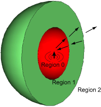
Figure 1 shows the configuration of a spherical cloak with outer radius and inner radius . The cloak layer within is a specified anisotropic and inhomogeneous medium with permittivity tensor and permeability tensor . According to Ref. Pendry et al. (2006), it is chosen such that and . Without loss of generality, we assume that the background material in the region has permittivity and permeability . A time-harmonic electric dipole is put inside as an active device. The electromagnetic waves from the dipole as well as the response of the surrounding environment can be decomposed into TE and TM modes with respect to , corresponding to scalar potentials and , whose expressions in the current case have been derived in Ref. Chen et al. (2007).
Since TE and TM modes in such a radially inhomogeneous medium can be shown to be decoupled Chew , the derivations for these two kinds of modes are identical to each other. We start with the case that an outgoing TM wave is excited in the concealed region. This outgoing wave will induce a standing wave in region , an outgoing wave and a standing wave in region , and an outgoing wave in region Chew , as shown in Fig. 1. Thus the scalar potentials in these three regions can be written as
| (1) | |||||
| (2) | |||||
| (3) |
where , , and are Riccati-Bessel Functions of the first, the second, and the third kind respectively; , , , and are the unknown expansion coefficients. Especially, and are called the general reflection coefficient and general transmission coefficient, respectively Chew .
For the sake of illustration, the inner boundary of the cloak is set at instead of and then the limit is taken Zhang et al. (2007). Consequently, four boundary equations can be listed utilizing the continuities of tangential and tangential at the outer boundary (Eq.(4) and (5)) and at the inner boundary (Eq.(6) and (7)):
| (4) | |||
| (5) | |||
| (6) | |||
| (7) |
After solving all the equations, it can be obtained that , indicating that no field exists in the cloak layer as well as the outside space. Meanwhile we can get that , which is important for later use. In addition, it follows that in the limit , is nonzero. Obviously, the value of this product in Eq.(6) is nonzero only at the inner boundary, bringing out the discontinuity of the tangential field across the inner boundary. This result is very interesting. Since both and are finite everywhere and no conductive media exist, it is unreasonable to include surface current to support this discontinuity, as the common boundary conditions do. It should be noted that due to the same reason the displacement surface currents introduced in the cylindrical cloak Zhang et al. (2007); Greenleaf et al. (2007) are not applicable in the present case.
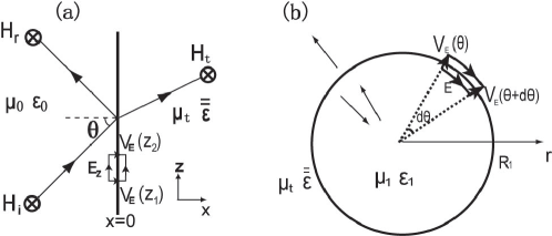
In order to understand this discontinuity, let us first consider a similar case in Cartesian coordinates as shown in Fig. 2(a), where a TM wave is obliquely incident () from free space onto an uniaxial medium with permittivity tensor and permeability . The dispersion relation in this medium is . Thus, when is very small, becomes imaginary and the transmitted wave becomes evanescent. In the limit , it can be found that the transmitted wave is so strongly evanescent that no fields exist in the region . More interestingly, in the limit , the integration has a finite value . In other words, is compressed on the interface like a delta function. This special finite and nonzero value can be named as an electric surface voltage . When a free charge moves to the interface, this voltage will push it to the other side and transfer energy to it. This voltage is not caused by conductive charges but an infinite polarization of the material on the interface, i.e. it corresponds to a distribution of polarized dipole moments on the interface. In addition, the tangential electric field at the left side of the interface is while that at the right side is zero, meaning the tangential field is discontinuous across the interface. However, since , as shown in Fig. 2(a), Faraday’s law still holds on this interface. Clearly, using this uniaxial material, which is the same with the inner boundary of the cloak, becomes a delta function and forms the electric surface voltage which supports the discontinuity of the tangential field. Meanwhile, the reflection coefficient becomes -1, meaning that this medium behaves like a PMC by means of controlling the medium’s electric response.
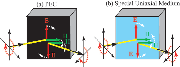
Similarly, the reflection coefficient for a TE wave is also -1 if goes to zero. Thus, the special uniaxial medium whose and go to zero simultaneously behaves like a PMC for TM waves due to electric surface voltages, and a PEC for TE waves due to magnetic surface voltages. This leads to another interesting aspect of the reflection. First, in the sense that there is a complete reflection, the interface behaves like a mirror. Second, this special mirror not only keeps the polarization but also the phase information of the reflected waves. For example, for a right-handed circularly polarized wave incident onto this boundary, the reflected wave retains its handness, but for a mere PEC or PMC boundary, the reflected wave becomes left-handed, as shown in Fig. 3. This property is similar to the SHS boundary used in radar and microwave engineering Lindell and Puska (1996). But for a SHS with its conducting vector fixed, if the incident plane changes, the phase of the reflected wave also changes. However, the phase of the reflected wave in Fig. 3(b) is independent on the incident plane, meaning it only depends on the optical path the wave travels. So, this mirror behaves the same in any plane of incidence, and the information of a source including the polarization and phase is entirely retained in the reflected wave.
From the above discussion in Cartesian coordinate system, we see that the surface voltages are introduced by the zero permittivity and permeability in the normal direction of the interface, which contribute to the discontinuity of the tangential electromagnetic fields across the boundary. This is also true for a spherical interface in spherical coordinate system. For example, as shown in Fig. 2(b), a sphere with permittivity and permeability is embedded in the homogeneous background medium with permittivity tensor and permeability . Similar to the case in Fig. 2(a), for TM waves, in the limit , no fields exist in the region , but the electric surface voltage is induced at the boundary. Since , Faraday’s law still holds across the boundary. The similar result can be obtained for component. Outgoing TE waves have similar derivation when goes to zero. Therefore the condition where the material at the inner boundary of a spherical cloak has radial permittivity and permeability of zero is sufficient for total reflection of all waves back by inducing surface voltages, no matter whether the outside medium satisfies the relation of constitutive parameters proposed in Ref. Pendry et al. (2006) or not. Mathematical treatment in time domain in Ref. Weder et al. (2007) has also gotten the similar result of complete reflection.
Based on the above discussion, the electric and magnetic surface voltages at the inner boundary as well as the field distribution inside the concealed region due to an electric dipole located at an arbitrary position (,,), where , can be derived. By expanding the wave from the dipole into spherical waves, the corresponding scalar potentials and for the incident waves can be obtained. Since it is known that the reflection coefficient for both TE and TM waves is , the scalar potentials of reflected waves, and , can be easily obtained. Consequently, the induced electric and magnetic surface voltages at the inner boundary of the spherical cloak can be calculated as follows
| (8) | |||
| (9) |
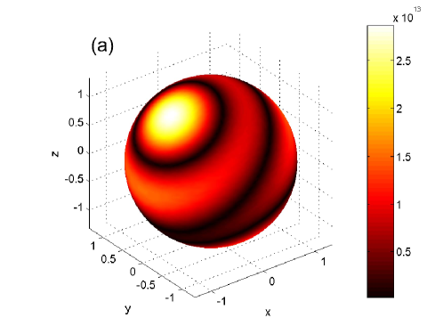
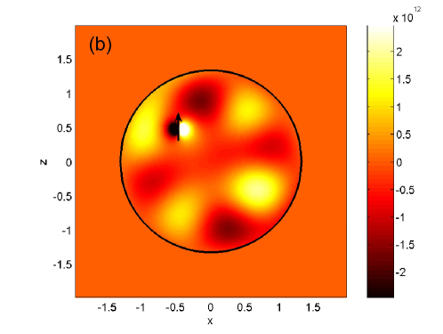
Figure 4 plots the amplitude of at the inner boundary of a spherical cloak and the field inside the concealed region in the - plane, due to an electric dipole pointing in direction and located at (, , ). Firstly, it is seen that surface voltages distributions are not uniform on the surface. But for an outside observer, the dipole is invisible since no wave propagates outside. Secondly, the field inside exists in the form of standing waves. Figure 4(b) shows the field at the moment that the magnetic field reaches maximum. After a quarter of cycle, the magnetic field becomes zero while the electric field reaches maximum. Since and are always out of phase, the time-averaged Poynting power is zero anywhere, meaning no time-averaged power flowing inside. In other words, the energy radiated from the dipole at this moment will be returned to the dipole the next moment. Thus the total energy inside will not blow up.
It can be calculated from Eqs.(8) and (9) that, in the presence of an electric dipole inside, when decreases to zero, becomes zero while survives. Similarly, if a static magnetic dipole is inside instead of a static electric dipole, vanishes while survives. The cloak for the static magnetic field can be realized artificially Wood and Pendry (2007). Since there is no magnetic charge in nature, this magnetic surface voltage induced by a static magnetic dipole must exist in the form of its equivalent electric surface current. The inner boundary in Ref. Wood and Pendry (2007) is made of superconductor which makes this surface current realizable.
Furthermore, the value of surface voltages can relate to another parameter directly. In derivation of the scalar potential in Ref. Chen et al. (2007), the condition Balanis , where represents the auxiliary electric scalar potential, is applied. It is interesting to note that . Similarly, . Thus these auxiliary scalar potentials, and , which were introduced originally as mathematical tools, have direct physical counterparts at the inner boundary of the cloak, i.e. surface voltages in this case.
In conclusion, the exact electromagnetic field solution to the Maxwell equations for a spherical cloak with an active source inside the concealed region is established. It is shown that, an infinite polarization of the material at the inner boundary of the cloak will induce the electric and magnetic surface voltages, which prevent all waves from going out. These peculiar surface voltages are rare in nature, but they do not violate the Maxwell equations. The handness of the polarization and phase information of the waves reflected from the inner boundary of the cloak are unchanged. Finally, these surface voltages due to an electric dipole inside the concealed region are found to be exactly equal to the auxiliary scalar potentials at the inner boundary of the cloak which gain physical counterparts in this case.
This work is supported by the ONR under Contract N00014-01-1-0713, the Chinese NSF under Grant 60531020, and China PSF under Grant 20060390331.
References
- Pendry et al. (2006) J. B. Pendry, D. Schurig, and D. R. Smith, Science 312, 1780 (2006).
- Leonhardt (2006) U. Leonhardt, Science 312, 1777 (2006).
- Alu and Engheta (2005) A. Alu and N. Engheta, Phys. Rev. E 72, 016623 (2005).
- Milton and Nicorovici (2006) G. W. Milton and N.-A. P. Nicorovici, Proc. R. Soc. A 462, 3027 (2006).
- Sihvola (2006) A. Sihvola, Prog. Electromagn. Res. pier-66, 191 (2006).
- Greenleaf et al. (2007) A. Greenleaf, M. Lassas, and G. Uhlmann, Math. Res. Lett. 10, 685(2003).
- Sheng (2006) P. Sheng, Science 313, 1399 (2006).
- Schurig et al. (2006a) D. Schurig, J. B. Pendry, and D. R. Smith, Opt. Express 14, 9794 (2006a).
- Cummer et al. (2006) S. A. Cummer, B.-I. Popa, D. Schurig, D. R. Smith, and J. B. Pendry, Phys. Rev. E 74, 036621 (2006).
- Zolla et al. (2007) F. Zolla, S. Guenneau, A. Nicolet, and J. B. Pendry, Opt. Lett. 32, 1069 (2007).
- Chen et al. (2007) H. Chen, B. I. Wu, B. Zhang, and J. A. Kong, Phys. Rev. Lett. 99, 063903 (2007).
- Zhang et al. (2007) B. Zhang, H. Chen, B. I. Wu, Y. Luo, L. Ran, and J. A. Kong, Phys. Rev. B 76, 121101(R) (2007).
- Schurig et al. (2006b) D. Schurig, J. J. Mock, B. J. Justice, S. A. Cummer, J. B. Pendry, A. F. Starr, and D. R. Smith, Science 314, 977 (2006b).
- Greenleaf et al. (2007) A. Greenleaf, Y. Kurylev, M. Lassas, and G. Uhlmann, Commun. Math. Phys. 275, 749 (2007).
- Lindell and Puska (1996) I. V. Lindell and P. Puska, IEE Proc.-Microw. Antennas Propag. 143, 417 (1996).
- (16) C. A. Balanis, eprint Advanced Engineering Electromagnetics, John Wiley&Sons, 1989.
- (17) W. C. Chew, eprint Waves and Fields in inhomogeneous Media, 2nd ed, IEEE Press, 1995.
- Greenleaf et al. (2007) A. Greenleaf, Y. Kurylev, M. Lassas, and G. Uhlmann, Opt. Express 15, 12717 (2007).
- Weder et al. (2007) R. Weder, arXiv:0704.0248v3 (2007).
- Wood and Pendry (2007) B. Wood and J. B. Pendry, J. Phys.: Condens. Matter 19, 076208 (2007).