Constraining spiral structure parameters through Galactic pencil-beam and large-scale radial velocity surveys
Abstract
We investigate the effect of spiral structure on the Galactic disk as viewed by pencil beams centered on the Sun, relevant to upcoming surveys such as ARGOS, SEGUE, and GAIA. We create synthetic Galactic maps which we call Pencil Beam Maps (PBMs) of the following observables: line-of-sight velocities, the corresponding velocity dispersion, and the stellar number density that are functions of distance from the observer. We show that such maps can be used to infer spiral structure parameters, such as pattern speed, solar phase angle, and number of arms. The mean line-of-sight velocity and velocity dispersion are affected by up to km/s which is well within the detectable limit for forthcoming radial velocity surveys. One can measure the pattern speed by searching for imprints of resonances. In the case of a two-armed spiral structure it can be inferred from the radius of a high velocity dispersion ring situated at the 2:1 ILR. This information, however, must be combined with information related to the velocities and stellar number density in order to distinguish from a four-armed structure. If the pattern speed is such that the 2:1 ILR is hidden inside the Galactic bulge the 2:1 OLR will be present in the outer Galaxy and thus can equivalently be used to estimate the pattern speed. Once the pattern speed is known the solar angle can be estimated from the line-of-sight velocities and the number density PBMs. Forthcoming radial velocity surveys are likely to provide powerful constraints of the structure of the Milky Way disk.
Subject headings:
stellar dynamics, spiral structure1. Introduction
It has been well established by now that the Milky way is not axisymmetric with both a central bar and spiral structure perturbing its disk. Due to our location in the Galactic plane both spiral and bar structure is impossible to observe directly. Galactic bar parameters such as orientation and pattern speed have been inferred indirectly from both asymmetries around the Galactic center (e.g., Blitz and Spergel 1991; Weinberg 1992) and its effect on the local velocity distribution of old stars, i.e., the Hercules stream (Dehnen, 1999, 2000; Fux, 2001; Minchev et al., 2007).
Spiral structure parameters, however, are much more uncertain. Current spiral density wave models (Fux, 2001; Lépine et al., 2001; De Simone et al., 2004; Quillen and Minchev, 2005) strongly disagree on the strength of the spiral structure, the number of arms, and the pattern speed. These models differ in their predictions of the induced velocity streaming at different angular positions in the Galaxy. For example, a four-armed density wave with velocity perturbations of km/s will exhibit rapidly varying radial and tangential velocity components with azimuth across distances of a few kpc, and we could expect to detect km/s variations in the mean line-of-sight stellar velocity as a function of the distance from the Sun. However, the strength of the spiral arm perturbation remains controversial. Based on the OGLE number counts, Paczynski et al. (1994) estimated that the Sagittarius-Carina arm has a factor of two increase in density compared to the underlying disk. This model is inconsistent with COBE studies which find a much smaller contrast () and show that the Perseus and Scu-Cru arms are more dominant (Drimmel and Spergel, 2001).
HI, CO, Cepheid, and far-infrared observations suggest that the Galactic disk contains a four-armed tightly wound structure. On the other hand, Drimmel and Spergel (2001) have shown that the near-infrared observations are consistent with a dominant two-armed structure. Lépine et al. (2001) suggest that locally the Milky Way can be modeled by the superposition of a two- and four-armed structure moving at the same pattern speed. By studying the nearby spiral arms, Naoz and Shaviv (2007) find that the Sagittarius-Carina arm is a superposition of two features, moving at different pattern speeds. The effect of a two- and four-armed structure, moving at different angular velocities, on the velocity dispersion of a galactic disk has been explored numerically by Minchev and Quillen (2006).
Estimates for the pattern speed of the Milky Way spiral structure, or equivalently, the Sun’s position with respect to resonances associated with spiral structure, span a large range of values. Reviewing previous work, Shaviv (2003) finds a clustering of estimates for the pattern speed of local spiral structure near , though other studies suggest . The model by Lépine et al. (2001) places the Sun near the corotation resonance ), and was fit to Cepheid kinematics. The recent gas dynamical studies (Martos et al., 2004; Bissantz et al., 2003) match the properties of the gas in nearby arms with a spiral pattern speed of . Martos et al. (2004) propose that a two-armed stellar structure consistent with the stellar distribution inferred from COBE could cause four-arms in the gas distribution near the Sun. The gas dynamical model proposed by Bissantz et al. (2003) with a similar spiral pattern speed matches HI and CO kinematics. The pattern speed of a spiral density wave can be tightly constrained from the location of its resonances. For example, Quillen and Minchev (2005) associated stellar streams in the solar neighborhood with the 4:1 ILR resonance of a two-armed pattern and were then able to tightly constrain the pattern speed of the driving spiral density wave to within 5%. Independent constraints on the pattern speed come from recent surveys of nearby open clusters (e.g. Dias and Lépine 2005) where the older clusters are found to have drifted further from their original density wave location. These authors concluded that the Sun is located near the CR. A solar circle near the CR is also favored by Lépine et al. (2001) and Naoz and Shaviv (2007).
In this paper we investigate how spiral structure parameters can be inferred from velocity and density maps resulting from pencil-beam and large-scale surveys of the Galaxy. At present the influence of spiral arms on the observed kinematic properties of the Galactic disk is very poorly understood. With the advent of future Galactic all-sky (GAIA, SEGUE) and pencil-beam (ARGOS, BRAVA) radial velocity surveys, large amounts of kinematic data will be collected. The types of dynamical constraints made possible with these new data sets is not currently known. We address that issue here with synthetic models for the purpose of exploring how spiral structure might be constraint from these data.
2. The simulations
We perform 2D test-particle simulations of an initially axisymmetric exponential galactic disk. In order to reproduce the observed kinematics of the Galactic disk, we use disk parameters consistent with observations (table 1). The reader is referred to Minchev and Quillen (2007) for a more detailed description of our simulation set up. In all of our simulations we start with an initially warm disk, i.e., the radial velocity dispersion at is where is the velocity of the local standard of rest. The background axisymmetric potential due to the disk and halo has the form , corresponding to a flat rotation curve.
We treat the spiral pattern as a small perturbation to the axisymmetric model of the galaxy by viewing it as a quasi-steady density wave in accordance with the Lin-Shu hypothesis (Lin et al., 1969). The spiral wave gravitational potential perturbation is expanded in Fourier components as
| (1) |
The parameter is related to the pitch angle of the spiral wave, , as , negative for trailing spirals with rotation counterclockwise, and are plane polar coordinates. The pattern speed is given by and the spiral strength by . For a two-armed structure the term dominates. Upon taking the real part of equation 1 the perturbation due to the two-armed spiral density wave becomes
| Parameter | Symbol | Value |
|---|---|---|
| Solar neighborhood radius | 1 | |
| Circular velocity at | 1 | |
| Radial velocity dispersion | ||
| scale length | ||
| Disk scale length | ||
| Spiral strength | ||
| Pitch angle |
| (2) |
Integrations are performed forward in time. The perturbation is grown from zero to its maximum strength in four rotation periods at . In order to improve statistics, positions and velocities are time averaged for 10 spiral periods. We distribute particles (stars) between in inner and outer galactic radii . New particles are added until the final number of outputs is . In addition, the two-fold symmetry of our model galaxy is used to double this number.
We present our results by changing the spiral pattern speed, , and keeping the solar radius fixed at . For a two-armed spiral pattern the primary resonances are the 2:1 inner and outer Lindblad resonances (ILR and OLR). Those are achieved when , respectively, where is the epicyclic frequency. Similarly, the second order resonances are the 4:1 Lindblad resonances (LRs) at . We examine a region of parameter space for a range of pattern speeds placing the SN between the 4:1 LRs.
3. Variation of Galaxy morphology with pattern speed
Interpretation of line-of-sight velocities with Galactic longitude and distance from the Sun is not straightforward. To help out we first discuss morphology as seen by an outside viewer.
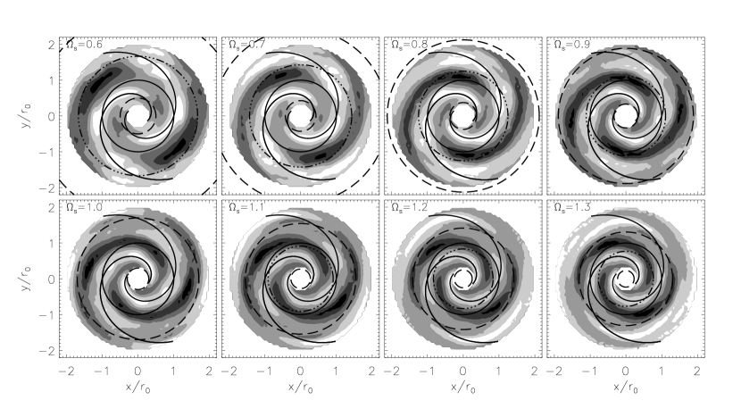
In figure 1 we present stellar number density contour plots for simulations of galactic disks with different pattern speeds. The background axisymmetric disk is subtracted to emphasize the spiral structure. The quantity plotted is , where and are the perturbed and axisymmetric stellar number densities. Concentric circles represent the 2:1 LRs (dashed), the solar radius (solid), and the CR (dash-dotted). Darker colors correspond to lower density. The inner disk is not plotted since we do not model the Galactic center. Each panel represents a simulation with a distinct pattern speed, , and all other parameters kept the same (see table 1). Pattern speeds considered range approximately between the 4:1 LRs, in units of 0.1. The minima of the two-armed spiral potential are graphed in each panel as solid curves. Note the crowding of resonances as the pattern speed increases.
In general, changing the solar radius in a simulation with the same pattern speed is equivalent to changing the pattern speed and keeping the solar radius fixed. However, this is exactly true only if the stellar density and velocity dispersion varied linearly with radius. This is not the case in real galaxies; both of these are found to vary exponentially with radius. Lewis and Freeman (1989) estimated the number density and radial velocity dispersion scale lengths in the Milky Way to be , and , respectively. Thus we need to perform different simulation runs when changing the pattern speed.
Note the disruption of the spirals near the 2:1 LRs (dashed circles). A rapid decrease of spiral strength at the 2:1 OLR was also observed by Vorobyov and Theis (2007) in a galactic disk model consisting of solving numerically the Boltzmann moment equations. It has also been suggested by Contopoulos (1985) that strong (nonlinear) spiral structure cannot extend beyond the 4:1 ILR since at that location the stellar orbits are not in phase with the imposed spiral. As pointed out by Sellwood (1993), however, this limited extent of the spirals found by Contopoulos (1985) is probably related to the restrictive assumptions they make in order to constructing self-consistent spiral structure. Another remarkable feature in the plots of figure 1 is the overdensity of stellar orbits just outside the 2:1 LRs (where they exist) and near the CR (dash-dotted circles). In the case of the CR, the enhancement is due to the stable Lagrange points associated with this resonance.
Assuming the primary spiral structure in the solar neighborhood is two-armed, the question arises: How can we determine any spiral structure parameters, given our inconvenient position in the Galaxy? One way to do this is by collecting a large number of stars with known velocities, distances, etc, and constructing velocity and density maps by plotting these versus Galactic longitude, and heliocentric distance, . In the next section we show what such maps would look like when a two-armed spiral structure perturbs a stellar disk. We examine different pattern speeds and solar positions with respect to a spiral arm. We call these maps ”Pencil Beam Maps” or PBMs.
4. Pencil Beam Maps (PBMs) of a Galactic disk perturbed by a two-armed spiral structure
To investigate the global structure of the Galaxy we require accurate stellar velocities and distances. In a pencil-beam spectroscopic survey line-of-sight velocities can be measured to great distances. On the other hand, proper motions are hard to measure for stars farther than about two kpc from the Sun. Thus those cannot be used in our investigation.
For a complete kinematic study accurate distance estimates are also needed. Due to the large distances involved in a such survey trigonometric parallax measurements are not possible. Instead, photometric distances can be estimated given accurate photometry. This way of computing distances, however, is hampered by the dust obscuration in the Galactic plane aside from several known windows, e.g., Baade’s Window at . Another distance estimator is the use of standard candles such as Cepheids, etc. Here we do not attempt to model the reddening resulting from dust extinction but present an idealized model as a first attempt to tackle this problem. A future paper will be dedicated to a more detailed modeling. Due to this shortcoming our model can be directly applied only to the known low extinction Galactic plane windows. Like Baade s window, the Scutum window at has low extinction and we can observe stars at 10 kpc distances towards the inner disk. Clump giants of the intermediate-age and older population of the disk and thick disk will be abundant in these fields. This line-of-sight at is tangent to the Scu-Cru spiral arm, with an AV extinction of about 3 mag at the distance of the spiral arm tangent point ( kpc). In the Scutum window, the HI and H profiles clearly show the presence of spiral arms (Madsen and Reynolds, 2005).
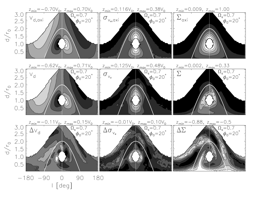
In figure 2 we present PBMs of the line-of-sight velocity (left column), the corresponding velocity dispersion (middle column), and the stellar number density (right column). This is a simulation of a galactic disk perturbed by a two-armed spiral density wave moving with . To create the contour plots in this figure we bin the disk in Galactic longitude (x-axis), and heliocentric distance (y-axis) as seen from an observer at a solar orientation with respect to the concave spiral arm of . This is in contrast to figure 1 where we present number density plots of a face-on view. The contours in the first row in figure 2 show the results of an axisymmetric disk, which is indicated by the subscript . In the second row the disk is perturbed by an spiral density wave. The third row in figure 2 plots contours of the difference between the perturbed and axisymmetric disks for the mean velocity and its dispersion: and . The number density, on the other hand, is obtained as in figure 1: We showed a number density plot in the x-y plane of this particular simulation in figure 1 (panel with ). In figure 2, however, we plot observables from a point of view centered on the Sun, as pencil-beam surveys would see the Galaxy. The shaded contours are equally spaced with darker color corresponding to lower density. On top of each panel we show the minimum and maximum contour values (in units of in the case of the velocities and the velocity dispersion). As it is commonly accepted, the Galactic longitude is zero in the direction of the Galactic center, with the Galactic anticenter at . The inner disk has been removed everywhere as in the density plots in figure 1. The white curve in each panel represents the projection of the solar circle in a PBM and the vertical line shows the Galactic longitude .

Note that in the background subtracted PBMs (third row) the spiral structure is much better pronounced compared to the raw values (first row). Knowing the global Galactic potential is imperative to extracting information from a PBM. This presents a problem since the Milky Way potential is not very well known. We could, however, use our model axisymmetric data to subtract from the observational data.
How well do we need to know the axisymmetric structure so that spiral features are not wiped out? From the third row of figure 2 we can estimate that distance uncertainties of do not prevent detection of spiral structure. We also need line-of-sight velocity precision of km/s and the axisymmetric potential must be known to within .
What information about the spiral structure can we infer from PBMs such as figure 2? To answer this question we need to vary the parameters and look at how structure in these PBMs changes. We do this in the following sections.
4.1. Changing the spiral pattern speed
We would like to know how to infer the spiral pattern speed from structure in the
PBMs.
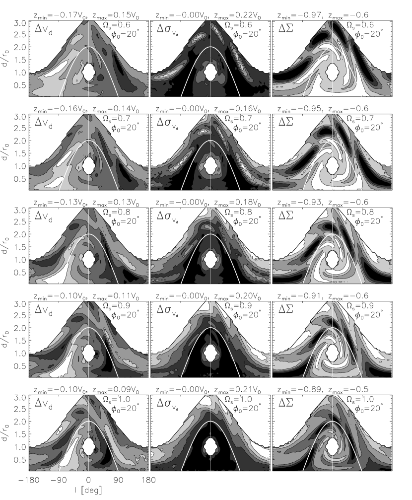
In figure 3 we plot the variation of PBMs with a change in the spiral
pattern speed in the range ; the solar orientation
with respect to the concave spiral arm is kept fixed at .
This range places the Sun from just inside the 4:1 ILR to the CR.
In contrast to figure
2 here all panels have the axisymmetric background subtracted to
reveal the symmetry of the spiral residuals.
We are now looking for features that are strong enough to be detected in an actual
pencil-beam survey. The values indicated above each panel
give the maximum error introduced by spiral structure in the otherwise axisymmetric
background disk. These values for the line-of-sight velocity , and its
standard deviation , are km/s for km/s
(left and middle columns in figure 3), which is well above the
resolution of upcoming radial velocity surveys ( km/s).
Strong features showing marked variation with the change in pattern speed are
apparent in all three observables:
(1) In the case of high positive and negative velocity groups
resulting from the effect of the 2:1 ILR are found at
and , respectively,
for (top left panel). With the increase of pattern speed,
these clumps spiral in a clockwise direction toward the Galactic center.
(2) The standard deviation of the line-of-sight velocities, , which
can also be described as the ”heating” (or the random motions) of stars,
peaks at a particular ring-like shape around the Galactic center for all pattern
speeds (middle column). These rings are associated with the 2:1 ILR induced by
the spiral density wave. It is clear that the radii of these rings are changing with
the change of the pattern speed and thus the location of the 2:1 ILR.
Beyond the CR () this resonance falls inside the inner
three kpc or inside the Galactic bulge. Thus, using the radius of this hot ring
to infer the location of the 2:1 ILR (and thus the pattern speed) is only valid
if values are in the range considered in figure 3.
(3) Lastly, the number density PBMs in figure 1 (right column)
are also indicative of the changing pattern speed. The disruption of the spiral
arms near the 2:1 LRs and variation in spiral strength due to the encounter the
second order resonances and CR, creates a large contrast in these axisymmetric
background subtracted PBMs.
Many of these features can be used in addition to the information extracted from
the velocities.
All of the features described above can be used to identify the location of the 2:1 ILR and thus the patter speed. As we mentioned, however, if the solar circle is placed at or beyond the CR, the 2:1 ILR falls inside the Galactic bulge. Consequently, the features created by it disappear. Fortunately, just as this happens the 2:1 OLR enters the Galactic disk (our disks extend to a radius of ) and similarly to the 2:1 ILR case, resonant features are created, this time in the outer parts of the disk.
4.2. Changing the Sun’s orientation with respect to a spiral arm
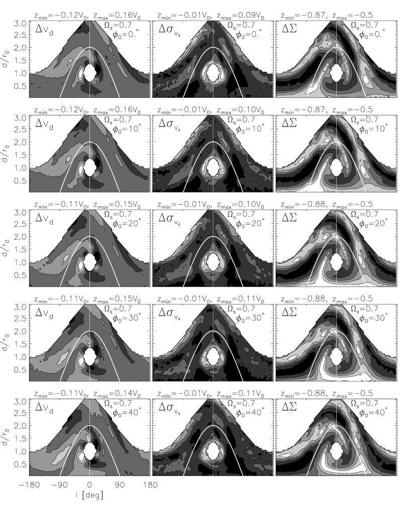
How can we infer the Sun’s azimuth with respect to the galactocentric line passing through the intersection of the Solar circle and a concave spiral arm? To find out we plot PBMs of simulation runs with the same pattern speed and different solar phase angle. Figure 4 shows such plots for a fixed and a solar phase angle changing from top to bottom in the range .
Similarly to figure 3 we now look for strong features in the
three observables that can be used to estimate :
(1) Inspection of the left column of figure 4 reveals a negative
velocity stream which changes position with a change of phase angle.
For (top left) this feature is centered on
at a heliocentric distance of . As the angle is
increased this steam moves to larger longitudes roughly preserving its distance
from the Sun. Note that the high positive and negative features discussed in
the context of in figure 3, do not vary as the angle is
changed since the pattern speed is kept fixed.
(2) The line-of-sight velocity dispersion (middle column of figure 3)
does not seem to be particularly useful for constraining the solar phase angle.
(3) Finally, the structure in the number density PBMs shows prominent variation with
the change in solar angle. For example pencil-beam observations at
would be drastically different depending on the phase angle.
In an actual survey we would first try to infer the position of the inner or outer LR as discussed in Section 4.1 and thus find the pattern speed.
5. Four-armed spiral structure
So far we have only discussed simulations involving a two-armed spiral density wave perturbation. In this section we show the effect of a four-armed structure, make comparison with the two-armed case and suggest a way to distinguish between the two.
Figure 5 shows PBMs of a galactic disk, similarly to figure 3, but perturbed by a four-armed spiral structure. As in figure 3 pattern speed changed from top to bottom in the range and the solar orientation with respect to a concave arm is kept fixed at . In this case the first order resonances are the 4:1 ILR/OLR which occur at , respectively.
As expected, more structure is apparent in all PBMs in the case of the four-armed structure. Note that the hot rings in present in the case of the two-armed structure (figure 3) are also apparent in the four-armed case although not as pronounced. The reason for this is the fact that the 2:1 ILR which causes these is a second order when . These hot rings can be used in both the two- and four-armed cases to estimate but are expected to be much stronger for . Inspecting and (left and right columns) in figure 3 and 5 it is clear that pencil-beam observations along Galactic longitudes or , for example, can unambiguously distinguish between and spiral structure, as the oscillation frequency doubles when .
6. Conclusion
Upcoming Galactic disk surveys will reveal the age, composition and phase space distribution of stars within the various Galactic components. These stellar excavations will provide essential clues for understanding the structure, formation and evolution of our Galaxy. To facilitate the interpretation of the huge amounts of data resulting from these surveys, Galactic disk models, such as the one presented here, are needed to interpret the observations.
We have investigated how the Milky Was spiral structure parameters, such as pattern speed and solar phase angle, can be estimated in a deep all-sky survey. We performed a series of test-particle simulations of a warm galactic disk approximating the disk kinematics of the Milky Way. We considered both two- and four-armed spiral structure and suggested a way to distinguish between the two using velocity and number density maps.
We found that the axisymmetric potential needs to be known to , line-of-sight velocities to km/s, and distance uncertainties need to be less than . The mean line-of-sight velocity and the velocity dispersion are affected by up to km/s which is well within the detectable limit for forthcoming radial velocity surveys. Pattern speed can be constrained by a hot ring at the 2:1 ILR in both two- and four-armed spiral structure. To distinguish between the two, however, we also need information related to the velocities and stellar number density. If the pattern speed is such that the 2:1 ILR is hidden inside the Galactic bulge the 2:1 OLR would be present in the outer Galaxy and thus can equivalently be used to estimate the pattern speed. Once the pattern speed is known the solar angle can be estimated from the number density variation with heliocentric distance; is also reflected in the PBMs.
Future work needs to address the issue of how to obtain the axisymmetric background potential needed to subtract from the observational data as discussed at the end of Section 4. Also, it is important to know what type of tracer stars are needed that would allow the estimation of photometric parallaxes with errors less than , and the distribution of those stars.
While here we only considered steady state spiral stricture, other theories of spiral structure, such as transient and swing-amplified spirals, need to be investigated as well. It has also been suggested that the Galaxy harbors two sets of spiral structure moving at the same (Lépine et al., 2001) or different (Naoz and Shaviv, 2007; Minchev and Quillen, 2006) pattern speeds. We expect in all those cases it will be again resonant features to relate to the pattern speed and solar angle. In the case of non-steady state spirals, however, the structure in the PBMs will vary with integration time and interpretation will become more complicated. We refer these cases to a future study.
It is also known that the Milky Way is a barred galaxy. The simulations performed here do not include the influence of the bar. This is not necessarily a shortcoming since most of the features in the PBMs we use to infer spiral structure parameters are caused by resonances and, unless a resonance overlap with the central bar exists in the same location, those would not be different when a bar is included in the simulations. Future work should also look at this problem.
References
- Bissantz et al. (2003) Bissantz, N., Englmaier, P., and Gerhard, O.: 2003, MNRAS 340, 949
- Blitz and Spergel (1991) Blitz, L. and Spergel, D. N.: 1991, ApJ 379, 631
- Contopoulos (1985) Contopoulos, G.: 1985, Comments on Astrophysics 11, 1
- De Simone et al. (2004) De Simone, R., Wu, X., and Tremaine, S.: 2004, MNRAS 350, 627
- Dehnen (1999) Dehnen, W.: 1999, ApJ 524, L35
- Dehnen (2000) Dehnen, W.: 2000, AJ 119, 800
- Dias and Lépine (2005) Dias, W. S. and Lépine, J. R. D.: 2005, ApJ 629, 825
- Drimmel and Spergel (2001) Drimmel, R. and Spergel, D. N.: 2001, ApJ 556, 181
- Fux (2001) Fux, R.: 2001, A&A 373, 511
- Lépine et al. (2001) Lépine, J. R. D., Mishurov, Y. N., and Dedikov, S. Y.: 2001, ApJ 546, 234
- Lewis and Freeman (1989) Lewis, J. R. and Freeman, K. C.: 1989, AJ 97, 139
- Lin et al. (1969) Lin, C. C., Yuan, C., and Shu, F. H.: 1969, ApJ 155, 721
- Madsen and Reynolds (2005) Madsen, G. J. and Reynolds, R. J.: 2005, ApJ 630, 925
- Martos et al. (2004) Martos, M., Hernandez, X., Yáñez, M., Moreno, E., and Pichardo, B.: 2004, MNRAS 350, L47
- Minchev et al. (2007) Minchev, I., Nordhaus, J., and Quillen, A. C.: 2007, ApJ 664, L31
- Minchev and Quillen (2006) Minchev, I. and Quillen, A. C.: 2006, MNRAS 368, 623
- Minchev and Quillen (2007) Minchev, I. and Quillen, A. C.: 2007, MNRAS 377, 1163
- Naoz and Shaviv (2007) Naoz, S. and Shaviv, N. J.: 2007, New Astronomy 12, 410
- Paczynski et al. (1994) Paczynski, B., Stanek, K. Z., Udalski, A., Szymanski, M., Kaluzny, J., Kubiak, M., and Mateo, M.: 1994, AJ 107, 2060
- Quillen and Minchev (2005) Quillen, A. C. and Minchev, I.: 2005, AJ 130, 576
- Sellwood (1993) Sellwood, J. A.: 1993, PASP 105, 648
- Shaviv (2003) Shaviv, N. J.: 2003, New Astronomy 8, 39
- Vorobyov and Theis (2007) Vorobyov, E. I. and Theis, C.: 2007, ArXiv e-prints 709
- Weinberg (1992) Weinberg, M. D.: 1992, ApJ 384, 81