Optical design of reflectionless complex media by finite embedded coordinate transformations
Abstract
Transformation optics offers an unconventional approach to the control of electromagnetic fields. A transformation optical structure is designed by first applying a form-invariant coordinate transform to Maxwell’s equations, in which part of free space is distorted in some desired manner. The coordinate transformation is then applied to the permittivity and permeability tensors to yield the specification for a complex medium with desired functionality. The transformation optical structures proposed to date, such as electromagnetic ”invisibility” cloaks and concentrators, are inherently reflectionless and leave the transmitted wave undisturbed. Here we expand the class of transformation optical structures by introducing finite, embedded coordinate transformations, which allow the electromagnetic waves to be steered or focused. We apply the method to the design of several devices, including a parallel beam shifter and a beam splitter, both of which exhibit unusual electromagnetic behavior as confirmed by 2D full-wave simulations. The devices are designed to be reflectionless, in accordance with a straightforward topological criterion.
pacs:
42.79.-e, 42.79.Fm, 42.79.Ls, 42.15.Eq, 02.40.-k, 02.70.DhMetamaterials offer an enormous degree of freedom for manipulating electromagnetic fields, as independent and nearly arbitrary gradients can be introduced in the components of the effective permittivity and permeability tensors. In order to exploit such a high degree of freedom a viable method for the well-aimed design of complex materials is required. Pendry et al. reported a methodology based on continuous form-invariant coordinate transformations of Maxwell’s equations which allows for the manipulation of electromagnetic fields in a previously unknown and unconventional fashion Pendry:2006 . This method was successfully applied for the design and the experimental realization of an invisibility cloak Schurig2:2006 . This work generated widespread interest specifically in the prospects of electromagnetic cloaking, a topic that has dominated much of the subsequent discussion Greenleaf:2006 ; Leonhardt:2006 ; Milton:2006 ; Milton2:2006 ; Cummer:2007 ; Cai:2007 ; Ruan:2007 ; Chen:2007 ; Wood:2007 ; Cummer:2006 ; Rahm:2007 ; Kong:2007 ; Cai2:2007 . All the transformation-optical designs reported in the literature so far have in common that the electromagnetic properties of the incident waves are exclusively changed within the restricted region of the transformation-optical device. However, for continuous transformations the field manipulation cannot be transferred to another medium or free space and thus remains a local phenomenon.
In this letter, we report a generalized approach to the method of form-invariant coordinate transformations of Maxwell’s equations based on finite embedded coordinate transformations. The use of embedded transformations adds a significant amount of flexibility to the transformation design of complex materials. For example, with finite-embedded transformations, it is possible to transfer field manipulations from the transformation-optical medium to a second medium, eliminating the requirement that the transformation optical structure be invisible to an observer. The finite-embedded transformation thus significantly broadens the range of materials that can be designed to include device-type structures capable of focusing or steering electromagnetic waves. Like transformation optical devices, the finite-embedded transform structures can be reflectionless under conditions that we describe below.
The mathematical formalism used for the calculation of the complex material properties is similar to the one reported in Schurig:2006 ; Rahm:2007 . Throughout this paper, we use the same terminology as introduced in these references.
For a given coordinate transformation (: Jacobi matrix, ), the electric permittivity and the magnetic permeability of the resulting material can be calculated by
| (1) | |||||
| (2) |
where denotes the determinant of the Jacobi matrix. For all the transformations carried out in this letter, the mathematical starting point is 3-dimensional euclidian space expressed in cartesian coordinates with isotropic permittivities and permeabilities and (: Kronecker delta).
A possible coordinate transformation for the design of a parallel beam shifter and a beam splitter consisting of a slab with thickness and height can be expressed by
| (3) | |||||
| (5) |
with
| (6) |
| (7) |
| (8) |
| (9) |
where is the maximum allowed width of the incoming beam, determines the shift amount and is the order of the nonlinearity of the transformation.
The transformation equations are defined for , and . For the case , equations (3)-(5) describe a parallel beam shifter whereas for the equations refer to a beam splitter. The Jacobi matrix of the transformation and its determinant are
| (10) |
| (11) |
with
| (12) | |||||
| (13) |
where
| (14) | |||||
| (15) |
and .
By equations (1)-(2) it is straightforward to calculate the tensors of the transformed relative electric permittivity and the relative magnetic permeability , which in the material representation are obtained as
| (16) |
where
| (17) |
is the metric tensor of the coordinate transformation.
At this point it should be mentioned, that only the domain with has to be considered in the material implementation which simplifies the mathematical expressions.
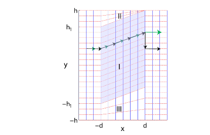
A linear coordinate transformation (l=1) for the design of a parallel beam shifter is illustrated in Fig. 1. The space within the grey shadowed region I () is tilted at an angle with respect to free space, which inherently results in a compression of space in region II and a dilution of space in region III. Considering the boundary between region I and free space, the coordinate systems are seen to be discontinuous at the interface . At this point, it is important to explain the difference between ”embedded transformations” and ”discontinuous transformations”. Interpreting the transformation as discontinuous, the boundary must be taken into account and the transformation of the y-coordinate at the transition from region I and free space must read
| (18) |
so that . As in the ray approximation the y-coordinate lines in fig. 1 represent the direction of the power flow for a beam propagating from to . The inclusion of the delta distribution in the material parameters would result in the trajectory indicated by the black arrows. The incoming wave would be shifted in the y-direction and abruptly be forced back on its old path at the boundary at , thereby rendering the entire beam shifting section invisible to an observer. However, as can be seen from equation (LABEL:eqn:ytrafo), the boundary is not included in the calculation of the material properties for the beam shifter and beam splitter. The coordinate transformation is carried out locally for the transformation-optical medium and then embedded into free space which results in the trajectory indicated by the green arrows. The beam is shifted in the y-direction and maintains its lateral shift after exiting the transformation-optical medium. This method is similar to the ”embedded Green function” approach in the calculation of electron transport through interfaces Inglesfield:1981 , so that we call it an ”embedded coordinate transformation”.
At this point, the question arises as to which conditions must hold for the embedded transformation in order to design a reflectionless optical device. We found as a necessary – and in our investigated cases also sufficient – topological condition that the metric in and normal to the interface between the transformation-optical medium and the non-transformed medium (in this case free space) must be continuous to the surrounding space. In the case of the beam shifter this means that the distances as measured along the x-, y- and z-axis in the transformation-optical medium and free space must be equal along the boundary (). As can be clearly seen from fig. 1, this condition is fulfilled by the embedded coordinate transformation of the beam shifter within the green shadowed region I. It should be mentioned, that the material properties in the domains II and III can be arbitrarily chosen as no fields penetrate into these regions.
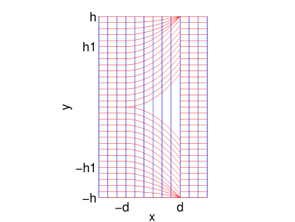
As a second, more sophisticated example a beam splitter is presented for the case of a nonlinear transformation of second order. The material properties are described by equation (16) with () and (. This specific coordinate transformation is illustrated in fig. 2. The underlying metric describes the gradual opening of a wedge-shaped slit in the y-direction. The metric in the x-direction is not affected by the transformation. Similar to the parallel beam shifter, the beam splitter obeys the topological condition in order to operate without reflection.
To confirm our findings, 2D full-wave simulations were carried out to adequately predict the electromagnetic behavior of waves impinging on a beam shifter and a beam divider, respectively. The calculation domain was bounded by perfectly matched layers. The polarization of the plane waves was chosen to be perpendicular to the x-y plane.
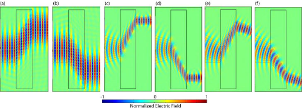
Fig. 3 depicts the spatial distribution of the real part of the transverse-electric phasor (color map) and the direction of the power flow (grey lines) of propagating waves across a parallel beam shifter at perpendicular (fig. 3a-d) and oblique incidence (fig. 3e-f). The curvature of the incoming wave fronts was freely chosen to be plane (a-b) or convergent (c-f). As can be seen from fig. 3a-b, the beam shifter translates the incoming plane wave in the y-direction perpendicular to the propagation x-direction without altering the angle of the wave fronts. In contrast, the direction of the power flow changes by an angle (: shift parameter) with respect to the power flow of the incoming plane wave. After propagation through the complex transformation-optical medium, the wave fronts and the power flow possess the same direction as the incoming beam, however the position of the wave is offset in the y-direction. The shift parameter was arbitrarily chosen to be 1.8 (fig. 3a) and -1.8 (fig. 3b).
A similar behavior can be observed for waves with wave fronts of arbitrary curvature, as for example for convergent waves (fig. 3c-f). In this case, the focus of the beam can be shifted within a plane parallel to the y-axis by variation of the shift parameter . As is obvious from fig. 3e-f, the same behavior applies for incoming waves at oblique incidence. The beam solely experiences a translation in the y-direction whereas the x-position of the focus remains unchanged. In all cases, the realized transformation-optical parallel beam shifter proves to operate without reflection confirming our metric criterion used for the design. The presented parallel beam shifter could play a crucial role in connection with tunable, reconfigurable metamaterials as it would allow scanning of a beam focus along a flat surface without changing the plane of the focus and without introducing a beam tilt or aberrations. These properties become even more significant for applications where short working distances are used between scanner and object.
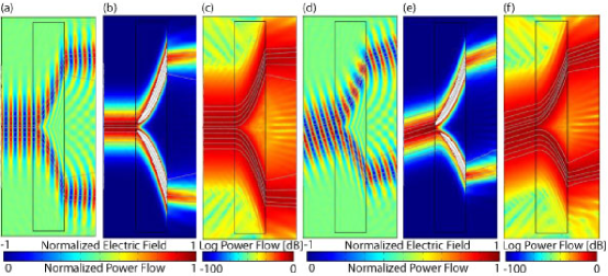
Similar simulations were carried out for the transformation-optical beam splitter. Fig. 4a shows the electric field distribution and the power flow lines for waves at perpendicular incidence. The beam splitter shifts one half of the wave in the (+y)-direction and the second half in the (-y)-direction, thus splitting the wave at the mid-point. The split waves are not perfectly parallel at the exit plane of the device due to diffraction of the incoming wave of finite width. As can be seen, there exists a small fraction of scattered fields within the split region which can be explained in terms of diffraction and scattering which is out of the scope of this letter. The beam splitter was found to operate without reflection in agreement with the metric criterion.
Fig. 4b displays the normalized power flow inside and outside the device. In order to enhance the contrast in the visualization of the power distribution at the beam splitter output, the color scale is saturated inside the beam splitter medium. As obvious from the transformation (fig. 2), the power density inside the transformation-optical medium is expected to be higher than outside the material, which is indicated by the density of the grid lines in fig. 2 and confirmed by the simulations. The power flow density abruptly decreases at the output facet of the beam splitter. For clarification, fig. 4c shows the power flow on a logarithmic scale. By integration of the power density inside the gap region between the beams and the power density inside either the upper or lower arm of the split beams a power ratio of 10:1 was calculated. The scattered waves in the gap carried about 4% of the total power.
In fig. 4d-f the spatial distribution of the transverse electric field (d) and the power flow on a linear (e) and a logarithmic scale (f) are shown for an obliquely incident wave on the beam splitter. Again, the beam is clearly divided into two beams with a small fraction of diffracted and scattered fields inside the gap between the split beams. As for perpendicular incidence, no reflection was observed in the simulation at both the input and output facet of the beam splitter. Similar to the result for perpendicular incidence, the propagation directions of the outgoing waves are not parallel. In addition, the angles of the central wave vectors of the split beams with refer to the central wave vector of the incident beam are not equal.
In conclusion, the concept of embedded coordinate transformations significantly expands the idea of the transformation-optical design of metamaterials which itself was restricted to continuous coordinate transformations so far. In contrast to continuous transformations, the expansion to embedded transformations allows for the first time to non-reversibly change the properties of electromagnetic waves in transformation media and to transmit the changed electromagnetic properties to free space or to a different medium in general. In order to design the medium as reflectionless, a new topological criterion for the embedded transformations was found, which imposes constraints to the metric of the spaces at the interface between the transformation-optical medium and the surrounding space. This metric criterion was applied in the conception of a parallel beam shifter and a beam splitter and confirmed in 2D full wave simulations. Both devices showed an extraordinary electromagnetic behavior which is not achievable by conventional materials. Both examples clearly state the significance of embedded coordinate transformations for the design of new electromagnetic elements with tunable, unconventional optical properties.
D. Schurig wishes to acknowledge support from the IC Postdoctoral Research Fellowship program.
References
- (1) J. B. Pendry, D. Schurig, D. R. Smith, Science 312, 1780 (2006).
- (2) D. Schurig, J. J. Mock, B. J. Justice, S. A. Cummer, J. B. Pendry, A. F. Starr, D. R. Smith, Science 314, 977 (2006).
- (3) A. Greenleaf, Y. Kurylev, M. Lassas, G. Uhlmann, www.arxiv.org/abs/math.AP/0611185 (2006).
- (4) U. Leonhardt, Science 312, 1777 (2006).
- (5) G.W. Milton,M. Briane, J. R. Willis, New J. Phys. 8, 248 (2006).
- (6) M. Rahm, D. Schurig, D. A. Roberts, S. A. Cummer, D. R. Smith, J. B. Pendry”, arXiv:0706.2452v1, also: doi:10.1016/j.photonics.2007.07.013 (2007).
- (7) G. W. Milton and N.-A. P. Nicorovici, Proc. Roy. Soc. London A 462, 1364 (2006).
- (8) S. A. Cummer and D. Schurig, New J. Phys. 9, 45 (2007).
- (9) W. Cai, U. K. Chettiar, A. V. Kildishev, V. M. Shalaev, Nature Photonics 1, 224 (2007).
- (10) Z. Ruan, M. Yan, C. W. Neff, M. Qiu, arXiv:0704.1183v2 (2007).
- (11) H. Chen and C. T. Chan, Appl. Phys. Lett. 90, 241105 (2007).
- (12) B. Wood and J. B. Pendry, J. Phys.: Condens. Matter 19, 076208 (2007).
- (13) S. A. Cummer, B.-I. Popa, D. Schurig, D. R. Smith, and J. B. Pendry, Phys. Rev. E 74, 036621 (2006).
- (14) H. Chen, B.-I.Wu, B. Zhang, and J. A. Kong, Phys. Rev. Lett. 99, 063903 (2007).
- (15) W. Cai, U. K. Chettiar, A. V. Kildishev, G. W. Milton, and V. M. Shalaev (2007), arXiv:0707.3641v1.
- (16) D. Schurig, J. B. Pendry, and D. R. Smith, Opt. Expr. 14, 9794 (2006).
- (17) J. E. Inglesfield, J. Phys. C: Solid State Phys. 14, 3795 (1981).