\runtitleRoma International Conference on Astro-Particle physics \runauthorMuon electromagnetic shower reconstruction
Algorithm for muon electromagnetic shower reconstruction
Abstract
The ANTARES neutrino telescope is presently being built in the Mediterranean Sea at a depth of 2500 m. The primary aim of the experiment is the detection of high energy cosmic muon neutrinos, which are identified by the muons that are produced in charged current interactions. These muons are detected by measuring the Cerenkov light which they emit traversing the detector. Sometimes a high momentum muon produces electromagnetic showers. The subject of this paper is a method to reconstruct these showers which includes several steps: an algorithm for the fit of the muon track parameters, preselection of detected photons belonging to a shower, and a final fit with the preselected detected photons to calculate the electromagnetic shower position. Finally a comparison between data obtained with that part of the detector that is currently in operation and simulations is presented.
1 Introduction
The ANTARES [1] detection principle relies on the observation of Cerenkov (CK) light emitted by relativistic charged particles in water. The emitted CK photons are detected by a 3-dimensional grid of 900 photomultiplier tubes (PMTs) arranged in 12 detection lines at a depth of 2500 m in the Mediterranean Sea. The detector will be completed in early 2008. Since the end of January 2007, the detector has 5 operating detection lines. Amongst others first data of atmospheric downward going muons have been measured, which are up to m long tracks with energies larger than GeV. This gives the unique opportunity to study the average number of showers per track length for high energy muons passing through sea water.
The muon track is reconstructed from the arrival times of the CK light detected by the PMTs, whose positions are known. The muon energy loss mechanism in water are ionization, pair production, bremsstrahlung, and photonuclear interactions. Above several hundred GeV the muon energy loss is dominated by the latter three effects [2], which are discrete and are characterized by large energy fluctuations. Furthermore, the average muon energy loss due to these effects is proportional to the energy of the muon.
In the following a method to reconstruct discrete electromagnetic (EM) showers is presented, which gives additional information about a muon track (e.g. the shower multiplicity) as compared to existing algorithms only measuring the direction and position of the muon track.
2 Identification of muon EM showers
The challenge of EM shower reconstruction is to distinguish CK photons from EM shower photons. The EM shower light has two key characteristics: it is produced in one point on the muon path and it arrives, in general, delayed compared to the CK light.

The first characteristic distinguishing CK light from EM shower light is illustrated in Fig. 1. The CK photons are emitted continuously along the muon path, whereas EM showers are emitted stochastically and discretely. Furthermore, the number of photons from EM showers is proportional to the deposited energy. By projecting the 3-dimensional position and arrival time of all detected photons onto the muon axis, the identification of EM showers is reduced to a one-dimensional problem. This transformed information is presented by a one-dimensional histogram, in which the EM shower position appears as a peak. So, the peak indicates where on the muon trajectory the EM shower is produced.
3 Algorithm for shower reconstruction
The algorithm consist of three steps using digitized PMT signals which are referred to as hits111 A hit occurs when a PMT signal crosses a threshold corresponding to 0.3 of a single photon-electron amplitude.. The first step selects muon candidates. Then, hits are preselected which originate from one distinct shower. The third step is a -minimization yielding the space-time position of the shower within the preselected hits.
3.1 Selection of shower hits
This section presents the mathematical framework which is schematically illustrated by Fig. 1.
Muon events are selected by using an existing muon reconstruction algorithm described in [3], which provides an estimate of the direction and position of the muon at some fixed time. For all hits in one muon event, the hit time is considered relative to the expected arrival time of a direct CK photon from the reconstructed muon track. This calculation can be simplified by a rotation of the coordinate system. The hits with of an event are rotated by the rotation matrix:
where and are given by the muon direction. The situation after the rotation of the -th measured hit as well as the rotated muon space-time coordinates is presented in Fig. 2.

The expected CK arrival time () of the photon is calculated by (see Fig. 2):
| (1) |
where is the speed of light in vacuum, is the refraction index of water, is the CK angle and is the perpendicular distance between the muon trajectory and the PMT given by .
3.1.1 Calculation of the photon emission point from the muon
In order to suppress random background hits, a selection is made of hits for which the difference between the calculated arrival time of CK photons and the measured arrival time is in the interval . Furthermore, this interval is subdivided in two unequal intervals, because photons from EM showers arrive in general later than CK photons. The early time interval contains CK photons and is given by . The late time interval contains mostly EM shower photons. The value for is given by the timing resolution of the PMT and the dispersion of light in water, whereas is defined by a value where the number of signal hits approaches the background level.
The emission location of photons from the early time interval is calculated under the CK angle assumption and is given by (see Fig. 2):
| (2) |
For the late time interval the unknown photon emission location is given by (see Fig. 2):
| (3) | |||||
where the second term is the time for a muon moving at speed of light to reach the point where the light is emitted, while the third term is the time needed for the light in water to travel from to the PMT. Eq. 3 corresponds to a quadratic equation with two distinct solutions222The late time interval ensures that two real solutions exist. represented by and .
3.1.2 Peak finder
All calculated , and positions are presented by a one-dimensional histogram. The upper panel of Fig. 3 shows an example of a full simulation of the detector response to an atmospheric muon event with background noise.
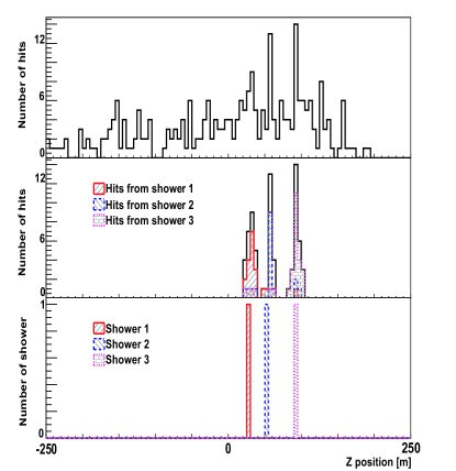
These , and positions are used by a one-dimensional peak finder algorithm. It selects peaks with amplitudes higher than a threshold identifying only statistically relevant peaks. The peak finder takes into account that if the two solution and are used in different peaks, the solution in the smaller peak is eliminated. The result of the peak finder is shown in the middle panel of Fig. 3. In addition hits produced from a particular shower are represented by a different hatching. The non-hatched hits are either produced by CK light or background noise.
In the lower panel of Fig. 3 the generated position of the three showers are also presented. The agreement between the middle and lower panel shows that the selected peaks in this event have a high hit-purity and the algorithm succeeds in properly reconstructing the shower position on the muon axes.
3.2 Reconstruction of the shower position
The last step of the algorithm is to calculate the EM shower space-time position under the assumption of a point-like shower source for each peak. For this, a first estimate of the shower space-time position as explained in [4] is used. Then for a peak with hits a with a fixed can be introduced:
| (4) | |||||
If necessary the is minimized by removing hits until among all possible permutations of the hits used to calculate the shower position a satisfactory normalized to the number of freedom is found.
The result of the algorithm is that for each muon candidate the shower multiplicity can be calculated. For each shower candidate different quantities can be evaluated: e.g. the position of the shower, the closest approach between shower position and muon track and the number of hits per shower.
4 Conclusion
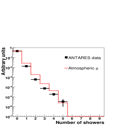
The performance of the reconstruction algorithm for EM showers induced by muons has been validated in a sample of simulated multiple atmospheric muon events with background noise. Next, the algorithm was applied to data obtained with ANTARES. The results of the shower multiplicity for down going muon events is shown in Fig. 4. The agreement between data and simulation is satisfactory. For the used set of selection cuts, the one shower muon events constitute about 5% of all muon events.
In summary a method to reconstruct EM showers from a muon has been developed and applied for the first time in ANTARES. The essential element of the algorithm is that the selection of shower hits is reduced to a one-dimensional problem. Improvements of the algorithm as well as a more extensive application to data are subject of the future work.
References
- [1] E. Aslanides et al., astro-ph/9907432
- [2] W.-M. Yao et al. 2006 J. Phys. G: “Nucl. Part. Phys.” 33 1
- [3] R. Bruijn, “Ph.D. Thesis”,Universiteit van Amsterdam, 2008 (in preparation)
- [4] B. Hartmann, arXiv:astro-ph/0606697v1