Further author information: (Send correspondence
to F.F.)
F.F: E-mail: frontera@fe.infn.it, Telephone: +39 0532 974 254
Development status of a Laue lens project for gamma-ray astronomy
Abstract
We report the status of the HAXTEL project, devoted to perform a design study and the development of a Laue lens prototype. After a summary of the major results of the design study, the approach adopted to develop a Demonstration Model of a Laue lens is discussed, the set up described, and some results presented.
keywords:
Laue lenses, gamma-ray instrumentation, focusing telescopes, gamma-ray observations1 INTRODUCTION
The hard X–/gamma–ray astronomy is moving toward a new generation of telescopes: from direct sky-viewing telescopes to focusing telescopes. Nowadays it is happening something similar to what happened in the late ’70s to the soft X–ray astronomy (2 keV) and in the ’90s to the 2–10 keV X–ray astronomy, in the first case with the Einstein satellite, in the second case with the launch of the ASCA and BeppoSAX satellites, when the first X–ray focusing telescopes were flown. With the advent of focusing telescopes in the hard X–/gamma–ray astronomy, it is expected a big leap in sensitivity, by a factor 10–100 with respect to one of the most sensitive instruments of the current generation, and a significant increase in angular resolution (from arcmin of the mask telescopes like the INTEGRAL IBIS to less than 1 arcmin).
Both the hard X-ray (100keV) and the gamma–ray ( 100 keV) focusing telescope generation make use of the Bragg diffraction technique, in the first case, from multilayer coatings (ML) in reflection configuration (supermirrors), in the second case, from mosaic crystals in transmission configuration (Laue lenses).
A mission proposal that makes use of both supermirrors and Laue lenses, named Gamma Ray Imager (GRI), has been recently submitted to ESA in response to the first AO of the ’Cosmic Vision 2015–2025’ plan [1]. It covers with unprecedented sensitivity the energy band from 10 keV to 1 MeV. While below 100 keV other missions are now under study, like Simbol-X [2] and NeXT [3], above 100 keV GRI is unprecedented. For the astrophysical importance of the 100 keV band see, e.g., Refs. 4, 5, 6.
Here we report on the current status of our project HAXTEL (= HArd X-ray TELescope) devoted to develop the technology for building broad energy passband Laue lenses, mainly for the study of the continuum emission of celestial sources above 100 keV.
2 Summary of the lens design study results
Results of the previous activity have been reported and discussed in Ref. 5. In short, the activity has mainly concerned a theoretical design study to establish the best design of a Laue lens telescope [7, 8], Monte Carlo simulations of the expected optical properties of Laue lenses [9], reflectivity measurements of mosaic crystal samples of Cu[111] [10]. We have investigated the geometry of the lens, the crystal material and lattice configuration that optimize the crystal reflectivity and energy passband. Given that we have to cover with good reflection efficiency a relatively broad energy band (several hundreds of keV), special crystals, with properly controlled lattice deformations, appear to be more useful. Crystals of this kind include mosaic crystals, bent crystals and crystals with non constant lattice spacing induced by doping materials or thermal gradients. For our project we have assumed mosaic crystals, made of crystallites misaligned each with other with controlled angular spread (FWHM of the Gaussian-like angular distribution of the crystallite misalignments). The growing technique of mosaic crystals with the desired spread is now being consolidated (e.g., Courtois et al.[11]).
Crystal tiles of thickness are assumed to have their mean crystalline plane normal to the tile main facets, which are assumed to be square of side .
To correctly focus photons, the direction of the vector perpendicular to the mean lattice plane of each crystal has to intersect the lens axis, while its inclination with respect to the focal plane has to be equal to the Bragg angle (see figure in Ref. 10). The angle depends on the distance of the tile center from the lens axis and on the focal length . For a correct focusing, it is needed that . Once the crystal material is established, the Bragg angle increases with , while the energy of the focused photons decreases with . More generally, once the focal length is established, the outer and inner lens radii, and , depend on the nominal energy passband of the lens (, ) and on the crystal lattice spacing: higher implies lower radii [5]. For given crystal material, outer lens radius and the focal length, the minimum energy that can be focused is established.
Thus, for a fixed inner and outer radius, the lens passband can be established by the use of a combination of different crystal materials. Among the candidate materials for their high reflectivity and for which the mosaic technology has been developed (see, e.g., Ref. 11), Cu[111] appears very promising for the hard X-/gamma–ray range [5]. However, for a long focal length (100 m), like in the case of the GRI mission, given the low lattice spacing value Å of Cu[111], the minimum photon energy that can be focused is 320 keV for an outer lens radius of 185 cm (that of GRI lens). The extension of the Laue lens passband below 320 keV can be obtained by the use of other crystal materials, e.g., Ge[111] with mosaic structure ( Å) or Si1-xGex[111] (Silicon Å) with a composition–gradient [12].
Mosaic spread and, for a fixed material, crystal thickness are the most crucial parameters for an optimization of the lens performance. A single crystal thickness is not the best solution for optimizing the lens effective area in its entire passband. However the optimization of the lens effective area at the highest energies could imply large thicknesses, that could be incompatible with lens weight constraints. We have investigated this issue [9], finding that a good compromize between crystal thickness and lens weight can be found.
Also the mosaic spread issue has been investigated. A higher spread gives a larger effective area, but also produces a larger defocusing of the reflected photons in the focal plane. By introducing a focusing factor
| (1) |
in which is the effective area of the lens and is the area of the focal spot which contains a fraction of photons reflected by the lens, it is found that, for long focal lengths like in the case of GRI (100 m), for its maximization, a very low spread (30 arcsec) is requested. However a lower spread requires a higher accuracy in the positioning of the crystals in the lens. A compromize has to be found.
Another issue we have investigated is the disposition of the mosaic crystal tiles in the lens for a uniform effective area of the lens passband. The best crystal tile disposition is an Archimedes’ spiral that provides a smooth behavior of the lens effective area with energy. However the Archimedes’ spiral becomes less important for long focal lengths ( 30 m) and other approaches are needed.
Also the required accuracy of the crystal tile positioning in the lens has been investigated [7]. It depends not only on the mosaic spread but also on the focal length. Higher focal lengths require higher positioning accuracies, which at the current stage of development is one of the major problems to be faced for the realization of a Laue lens.
Results from a Monte Carlo (MC) code, that has been developed to derive the properties of different lens configurations, like their Point Spread Functions (PSF), for either on–axis and off–axis incident photons, have been already reported [8, 9, 5]. They confirm the results obtained from the theoretical investigation and extend them.
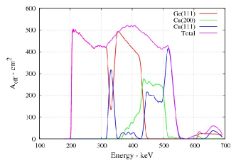
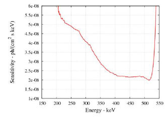
We show in Fig. 1 the expected on–axis effective area and 3 sensitivity of the lens described in Table 1. This lens configuration nicely fits also the GRI requirements.
The expected angular resolution of the lens is better than 1 arcmin.
| Parameter | |
|---|---|
| Focal length (m) | 100 |
| Nominal passband (keV) | 200–530 |
| Inner radius (cm) | 88 |
| Outer radius (cm) | 185 |
| Crystal material | Ge[111], Cu[111], Cu[200] |
| Mosaic spread (arcmin) | 0.5 |
| Tile cross section (mm2) | |
| Tile thickness (mm) | optimized |
| Number of crystal rings | 61 |
| No. of tiles | 17661 (Ge[111]), 3254 (Cu[200]), 3386 (Cu[111]) |
| Crystal weight (kg) | 155 |
| Effective area (cm2) @ 200 keV | 500 |
| Effective area (cm2) @ 400 keV | 530 |
| Effective area (cm2) @ 511 keV | 430 |
| Half power radius(mm) | 12 |
3 Demonstration Model Development
A lens Demonstration Model (DM) is being developed. Unlike the Laue lens in Ref. 14, the lens under development will be made of crystal tiles rigidly fixed to the lens frame, without mechanisms for adjustment of their orientation. Thus their positioning in the lens has to be correctly performed during the lens assembling. The goal of the DM development is just to establish the best crystal assembling technique of the lens. Figure 2 shows the drawing of the DM under development.
It is composed of a ring of 20 mosaic crystals with diameter of 36 cm. The tiles are made of Cu[111] with arcmin spread, 1515 mm2 front surface and 2 mm thickness.
3.1 Lens assembly technique
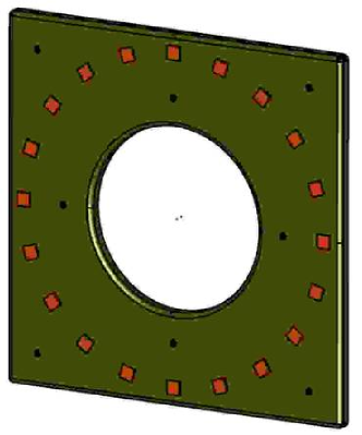
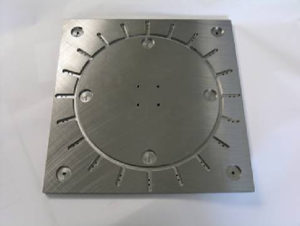
The adopted lens assembling technique is based on the use of a counter-mask (see Fig. 3). The counter-mask is provided with holes, two for each crystal, with their axes directed toward the center of curvature of the lens. Actually, in the case of the DM under development, the hole axis is parallel to that of the lens axis. This simplification has been adopted in this phase in order to focuse gamma–rays coming from a source at finite distance from the lens. In our case m.
Each crystal tile is positioned on the counter-mask by means of two pins (see Fig. 4) that are glued to each crystal with their axis parallel to the direction of the average crystalline plane.
Once each crystal is positioned on the counter-mask, the lens frame is glued to all the crystals. The lens frame is made of carbon fiber and is obtained starting from a mould. The lens is then separated from the counter-mask by means of a chemical treatment that dissolves an aluminum cup that covers the pin base closest to the crystal.
Thus the assembling of the DM lens comprises the following main activities:
-
•
Proper alignment of each crystal on the X–ray optical bench;
- •
-
•
Positioning of all crystals (with support pins) on the counter-mask;
-
•
Bonding of all crystals to the lens frame;
-
•
Chemical etching of the support pins, and removal of the counter-mask.
3.2 Test facility
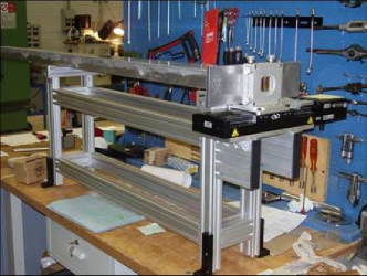
The set up for the crystalline plane determination and for the alignment of the two pins with the crystalline plane direction, along with the gluing system of the pins to the crystal tiles, is shown in Fig. 10.
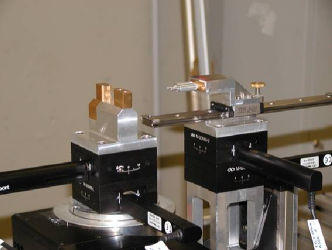
It is located in the X–ray facility LARIX (LARrge Italian X–ray facility) of the University of Ferrara (for a description see Ref. 15). The gluing is performed when the crystal correctly reflects the X–ray beam toward the lens focus.
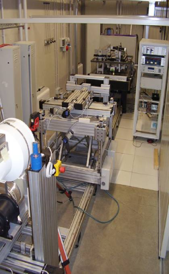
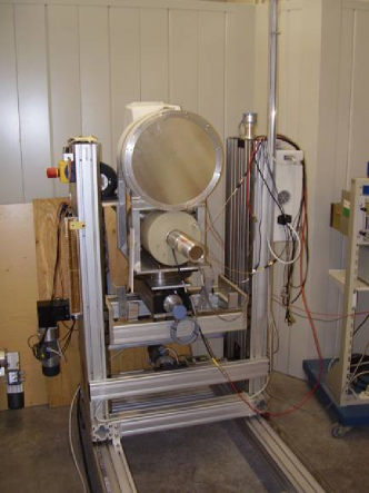
A view of the experimental apparatus for assembling and testing the lens DM is shown in Fig. 6.
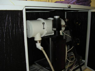
The apparatus includes an X–ray generator tube (see Fig. 7) with a Tungsten target, a fine focus of 0.4 mm radius, a maximum voltage of 150 kV and a maximum power of W. The X–ray tube, mounted on (X,Z) translation stage, is located in a lead box in which a hole is made in correspondence of the X–ray.
The X–ray photons coming out from the hole are collimated by a pyramidal collimator, at the end of which it is mounted a Tantalum slit with selectable aperture along the vertical and the horizontal directions, both perpendicular to the pyramid axis. The slit can be also translated perpendicularly to the pyramid axis (see Fig. 8). The slit defines the cross section of the X–ray beam that irradiates the crystal main surface.
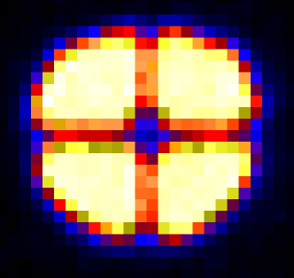
The radiation coming out from the slit collimator is used to both determine the mean lattice crystalline plane of the crystal tile and to align the pins to the X–ray beam. The image and spectrum of the X–ray beam, either the direct one or that transmitted through the crystal tile or that diffracted, can be detected. The available detectors include an X–ray imager, a cooled HPGe detector and a position sensitive scintillator detector (see Fig. 9). All of them can be rotated along the horizontal axis, and can be translated along the vertical and along the horizontal. The position resolution of the X–ray imager is 0.3 mm.
3.3 Determination of the average crystalline plane
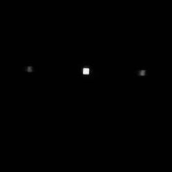
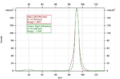
In order to determine the direction of the average lattice plane of the mosaic crystal tiles using the set up shown in Fig. 5, the crystal tile is located on a crystal positioner. This can be rotated around a vertical axis and tilted along two orthogonal axes until the diffracted beam from two symmetrical orientations of the crystal tile give symmetrical images and coincident spectra (see Fig. 10). An accuracy better than 10 arcsec in the determination of the average crystalline plane is achieved.
3.4 Alignment of the pin axis to the average crystalline planes
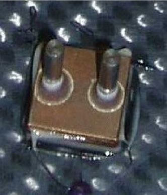
The 2 pins needed for each crystal are mounted on the pin positioner (see Fig. 5). This can be rotated along a circle with its center located in the vertical axis of the crystal positioner, and can be tilted along two orthogonal directions like the crystal positioner. The pin axis is requested to be parallel to the beam axis, previously made parallel to the average crystalline plane. This alignment is obtained by using X–ray shadow projected by two Tungsten crosses located along the pin positioner, with their axes parallel to the pin axes (see Fig. 11).
4 DM assembling status
A preliminar DM model with few mosaic crystal tiles of Cu[111] with arcmin spread is expected to be assembled and tested in a short time to evaluate the cumulative error budget of the assembling technique. Soon after, the DM model made of a ring of Cu[111] mosaic crystal tiles will be assembled. Results of the first rigid Laue lens are expected in a few month time.
Acknowledgements.
We acknowledge the financial support by the Italian Space Agency ASI and a minor contribution by the Italian Institute of Astrophysics (INAF). The design study was also possible thanks to the received Descartes Prize 2002 of the European Committee.References
- [1] J. Knödlseder, “GRI: focusing on the evolving violent universe,” in Optics of EUV, X–ray and Gamma–ray Astronomy III. Edited by O’Dell, Stephen L.; Pareschi, Giovanni. Proceedings of the SPIE, this issue., S. L. O’Dell and G. Pareschi, eds., Presented at the Society of Photo-Optical Instrumentation Engineers (SPIE) Conference 6688, July 2006.
- [2] P. Ferrando, M. Arnaud, U. Briel, O. Citterio, R. Clédassou, P. Duchon, F. Fiore, P. Giommi, A. Goldwurm, G. Hasinger, E. Kendziorra, P. Laurent, F. Lebrun, O. Limousin, G. Malaguti, S. Mereghetti, G. Micela, G. Pareschi, Y. Rio, J. P. Roques, L. Strüder, and G. Tagliaferri, “Simbol-X: mission overview,” in Space Telescopes and Instrumentation II: Ultraviolet to Gamma Ray. Edited by Turner, Martin J. L.; Hasinger, Günther. Proceedings of the SPIE, Volume 6266, pp. 62660F (2006)., M. J. L. Turner and G. Hasinger, eds., Presented at the Society of Photo-Optical Instrumentation Engineers (SPIE) Conference 6266, July 2006.
- [3] T. Takahashi, K. Mitsuda, and H. Kunieda, “The NeXT mission,” in Space Telescopes and Instrumentation II: Ultraviolet to Gamma Ray. Edited by Turner, Martin J. L.; Hasinger, Günther. Proceedings of the SPIE, Volume 6266, pp. 62660D (2006)., M. J. L. Turner and G. Hasinger, eds., Presented at the Society of Photo-Optical Instrumentation Engineers (SPIE) Conference 6266, July 2006.
- [4] F. Frontera, A. Pisa, P. de Chiara, and et al., “Exploring the hard X-/soft gamma-ray continuum spectra with Laue lenses,” in ESA Special Publication, F. Favata, J. Sanz-Forcada, A. Giménez, and B. Battrick, eds., ESA Special Publication 588, pp. 323–+, Dec. 2005.
- [5] F. Frontera, A. Pisa, V. Carassiti, F. Evangelisti, G. Loffredo, D. Pellicciotta, K. H. Andersen, P. Courtois, L. Amati, E. Caroli, T. Franceschini, G. Landini, S. Silvestri, and J. B. Stephen, “Gamma-ray lens development status for a European gamma-ray imager,” in Space Telescopes and Instrumentation II: Ultraviolet to Gamma Ray. Edited by Turner, Martin J. L.; Hasinger, Günther. Proceedings of the SPIE, Volume 6266, pp. 626627 (2006)., M. J. L. Turner and G. Hasinger, eds., Presented at the Society of Photo-Optical Instrumentation Engineers (SPIE) Conference 6266, July 2006.
- [6] J. Knödlseder, “GRI: the gamma-ray imager mission,” in Space Telescopes and Instrumentation II: Ultraviolet to Gamma Ray. Edited by Turner, Martin J. L.; Hasinger, Günther. Proceedings of the SPIE, Volume 6266, pp. 626623 (2006)., M. J. L. Turner and G. Hasinger, eds., Presented at the Society of Photo-Optical Instrumentation Engineers (SPIE) Conference 6266, July 2006.
- [7] A. Pisa, F. Frontera, P. De Chiara, G. Loffredo, D. Pellicciotta, G. Landini, T. Franceschini, S. Silvestri, K. Andersen, P. Courtois, and B. Hamelin, “Feasibility study of a Laue lens for hard x rays for space astronomy,” in Advances in Computational Methods for X-Ray and Neutron Optics. Edited by Sanchez del Rio, Manuel. Proceedings of the SPIE, Volume 5536, pp. 39-48 (2004)., M. Sanchez del Rio, ed., Presented at the Society of Photo-Optical Instrumentation Engineers (SPIE) Conference 5536, pp. 39–48, Oct. 2004.
- [8] A. Pisa, F. Frontera, P. De Chiara, G. Loffredo, D. Pellicciotta, V. Carassiti, F. Evangelisti, K. Andersen, P. Courtois, B. Hamelin, L. Amati, G. Landini, T. Franceschini, and S. Silvestri, “Development status of a Laue lens for high energy x-rays (60 keV),” in Optics for EUV, X-Ray, and Gamma-Ray Astronomy II. Edited by Citterio, Oberto; O’Dell, Stephen L. Proceedings of the SPIE, Volume 5900, pp. 350-359 (2005)., O. Citterio and S. L. O’Dell, eds., Presented at the Society of Photo-Optical Instrumentation Engineers (SPIE) Conference 5900, pp. 350–359, Aug. 2005.
- [9] A. Pisa, F. Frontera, G. Loffredo, D. Pellicciotta, and N. Auricchio, “Optical properties of Laue lenses for hard X-rays (60 keV),” Experimental Astronomy 20, pp. 219–228, Dec. 2005.
- [10] D. Pellicciotta, F. Frontera, G. Loffredo, A. Pisa, K. Andersen, P. Courtois, B. Hamelin, V. Carassiti, M. Melchiorri, and S. Squerzanti, “Laue Lens Development for Hard X-rays (60 keV),” IEEE Trans. Nucl. Sci. 53, pp. 253–258, 2006.
- [11] P. Courtois, B. Hamelin, and K. H. Andersen, “Production of copper and Heusler alloy Cu2MnAl mosaic single crystals for neutron monochromators,” Nuclear Instruments and Methods in Physics Research A 529, pp. 157–161, Aug. 2004.
- [12] N. V. Abrosimov, “Mosaic and gradient SiGe single crystals for gamma ray Laue lenses,” Experimental Astronomy 20, pp. 185–194, Dec. 2005.
- [13] F. Frontera, A. Pisa, G. Loffredo, D. Pellicciotta, V. Carassiti, F. Evangelisti, K. Andersen, P. Courtois, L. Amati, E. Caroli, T. Franceschini, G. Landini, S. Silvestri, and J. Stephen, “HAXTEL: A Laue lens telescope development project for a deep exploration of the hard X-ray sky (60 keV),” Experimental Astronomy 20, pp. 241–251, Dec. 2005.
- [14] P. von Ballmoos, H. Halloin, G. K. Skinner, R. K. Smither, J. Paul, N. V. Abrosimov, J. M. Alvarez, P. Astier, P. Bastie, D. Barret, A. Bazzano, A. Boutonnet, P. Brousse, B. Cordier, T. Courvoisier, G. Di Cocco, A. Giuliani, B. Hamelin, M. Hernanz, P. Jean, J. Isern, J. Knödlseder, P. Laurent, F. Lebrun, A. Marcowith, V. Martinot, L. Natalucci, J.-F. Olive, R. Pain, R. Sadat, H. Sainct, P. Ubertini, and G. Vedrenne, “MAX: a gamma-ray lens for nuclear astrophysics,” in Optics for EUV, X-Ray, and Gamma-Ray Astronomy. Edited by Citterio, Oberto; O’Dell, Stephen L. Proceedings of the SPIE, Volume 5168, pp. 482-491 (2004)., O. Citterio and S. L. O’Dell, eds., Presented at the Society of Photo-Optical Instrumentation Engineers (SPIE) Conference 5168, pp. 482–491, Feb. 2004.
- [15] G. Loffredo, F. Frontera, D. Pellicciotta, A. Pisa, V. Carassiti, S. Chiozzi, F. Evangelisti, L. Landi, M. Melchiorri, and S. Squerzanti, “The Ferrara hard X-ray facility for testing/calibrating hard X-ray focusing telescopes,” Experimental Astronomy 20, pp. 413–420, Dec. 2005.