Nonlinear Photonic Quasicrystals for Novel Optical Devices
Abstract
Two well-known methods for the design of quasicrystal models are used to create novel nonlinear optical devices. These devices are useful for efficient three-wave mixing of several different processes, and therefore offer greater flexibility with respect to the more common periodic nonlinear photonic crystals. We demonstrate applications for polarization switching as well as multi-wavelength and multi-directional frequency doubling. The generalized dual grid method is proven to be efficient for designing photonic quasicrystals for one-dimensional collinear devices as well as elaborate two-dimensional multi-directional devices. The cut and project method is physically realized by sending finite-width optical beams at an irrational angle through a periodic two-dimensional nonlinear photonic crystal. This enables two simultaneous collinear optical processes that can be varied by changing the angle of the beams.
1 Introduction
Twenty five years have passed since the 1982 discovery of quasicrystals [1], and we have yet to find a satisfying application that takes advantage of their unique combination of physical properties [2]. Nevertheless, interesting applications are starting to emerge that take advantage of quasiperiodic long-range order in metamaterials, or artificially constructed quasicrystals111We refer the reader to Ref. [3] for a precise definition of the term ‘quasicrystal’.. Most applications are based on linear photonic crystals, where quasiperiodic modulations of the index of refraction of a material are used in order to engineer its optical response. In particular, the fact that there are no restrictions on the order of the rotational symmetry of a quasicrystal is used to obtain nearly-isotropic photonic band gaps [4, 5]. Here we focus on metamaterials in the nonlinear optical domain, where recent technological progress has enabled to modulate the second-order nonlinear susceptibility with micron-scale resolution in various materials, such as ferroelectrics (our focus here), semiconductors, and polymers. In these nonlinear photonic crystals the modulation can be achieved by planar techniques, thereby offering either one or two dimensions for modulation. Moreover, there are no photonic bandgaps in these metamaterials, because the first-order susceptibility, and hence the refractive index, remain constant. The advantage of using quasicrystals in this case is not in their arbitrarily-high symmetry, but rather in the fact that there is no restriction on the combinations of wave vectors that may appear in their reciprocal lattices (provided that the symmetry of the quasicrystal is not of particular importance [6, 7]).
The novel optical devices described below are based on materials that facilitate the nonlinear interaction between light waves in the form of three-wave mixing. These are processes in which two incoming waves of frequencies and interact through the quadratic dielectric tensor of the material to produce a third wave of frequency ; or the opposite processes in which a single wave spontaneously breaks up into two. Three-wave mixing is severely constrained in dispersive materials, where is not a linear function, because the interacting photons must also conserve their total momentum. Even the slightest wave-vector mismatch appears as an oscillating phase that averages out the outgoing wave, giving rise to the so-called “phase-matching problem.” We have recently explained how one could fully solve the most general phase-matching problem using well-known ideas from the theory of quasicrystals [8]. The solution is based on the idea that in crystals222We refer the reader to Ref. [9] for a detailed discussion on “What is a crystal?”., whether periodic or not, continuous translation symmetry is broken. As a consequence, momentum conservation is replaced by the less-restrictive conservation law of crystal momentum whereby momentum need only be conserved to within a wave vector from the reciprocal lattice of the crystal. The fabrication of an efficient frequency-conversion device is therefore a matter of reciprocal-lattice engineering—designing an artificial crystal, from the quadratic dielectric field of the material , whose reciprocal lattice contains any desired set of mismatch wave vectors , , required for phase matching any arbitrary combination of three-wave mixing processes. In fact, the field amplitude of the output beam, in each frequency-conversion process, is linearly proportional to the amplitudes of each of the input beams, as well as the Fourier coefficient of the relevant mismatch wave vector [10].
The idea of using a one-dimensional periodic modulation of the relevant component of the quadratic dielectric tensor, for the purpose of phase matching a single three-wave process, was suggested already in the early 1960’s [11, 12, 13], and is termed “quasi-phase matching”. Since then this approach has been generalized using more elaborate one-dimensional [10, 14, 15] and two-dimensional [16, 17, 18, 19] designs, but only as ad hoc solutions for multiple processes. We argue that engineering the reciprocal lattice, of a nonlinear photonic quasicrystal, to contain any desired set of mismatch vectors—a task that 25 years of research in quasicrystals have taught us how to solve—provides the most general solution for the long-standing problem of multiple phase-matching. Here we describe a number of novel optical devices that have actually been fabricated using these ideas, and tested experimentally. In Sec. 2 we describe devices that have been designed using the dual-grid method in order to engineer the required nonlinear photonic quasicrystals. These devices attest to the general nature of the quasicrystal-based solution to the multiple phase-matching problem. In Sec. 3 we show that for collinear devices, in which all the participating waves propagate in the same direction, a certain degree of flexibility can be obtained by using a physical realization of the cut-and-project approach, in which one generates the required 1-dimensional photonic quasicrystal by cutting through a periodic crystal in 2 dimensions.
2 Reciprocal-lattice engineering with the dual-grid method
After selecting the nonlinear medium of choice and the appropriate operating temperature for a given frequency-conversion application, one can calculate the required set of mismatch vectors , , that are to be engineered into the reciprocal lattice of the nonlinear photonic quasicrystal. As we have described in Ref. [8], once these mismatch vectors are known, one can use de-Bruijn’s dual grid method [20], as generalized by Gähler and Rhyner [21] and later by Rabson, Ho, and Mermin [22, 23], in order to design the required quasicrystal. If the mismatch vectors are integrally-independent, one simply uses each vector , , to define a family of equally-spaced parallel lines, separated by , and oriented in the direction of . The set of all families constitutes the dual grid, which is then used in the standard manner [24] to define a set of tiling vectors , and to calculate the integral linear combinations of these tiling vectors that form the vertices of the tiles in the desired quasicrystal. The final step is to decorate each tile with an optimal motif, i.e. to decide which regions of the tile will be altered such that the relevant components of the quadratic dielectric tensor are positive, leaving the remaining background with an unchanged negative . If the mismatch vectors happen to be linearly-dependent, one has to consider the pros and cons of selecting a linearly-independent subset vs. using the full linearly-dependent set for generating the dual grid [8].
2.1 One dimensional implementation
As a rather simple demonstration of our general solution to the phase-matching problem, we have recently implemented a three-wave doubler [25]. The reader who is interested in implementing his or her own devices, based on our solution to phase-matching problem, is kindly referred to this article for a detailed pedagogical explanation of each and every step. This is a one-dimensional device that is able to phase match three collinear second harmonic generation processes simultaneously, taking three input beams with wavelengths 1530nm, 1550nm, and 1570nm, and producing three output beams at twice their frequencies. We note that the three processes implemented in this device are independent, and therefore could also be phase matched by fabricating a sequence of three periodic nonlinear photonic crystals, one for each frequency doubling process. Nevertheless, we were able to show that it is more efficient to simultaneously phase match all three process in a single quasiperiodic nonlinear photonic crystal.
Here we implement a more elaborate one-dimensional device utilizing our method, which is a nonlinear polarization switch [26]. This device takes a beam of frequency and polarization , propagating in the direction, and converts some of its energy into a beam of the same frequency, propagating in the same direction, but with polarization . It is a cascaded device [27] in which the output of the first process is used as the input of the second process. The first is a standard (type I) second harmonic generation process with , followed by a (type II) difference frequency generation process, in which the lower-frequency waves have different polarizations, .
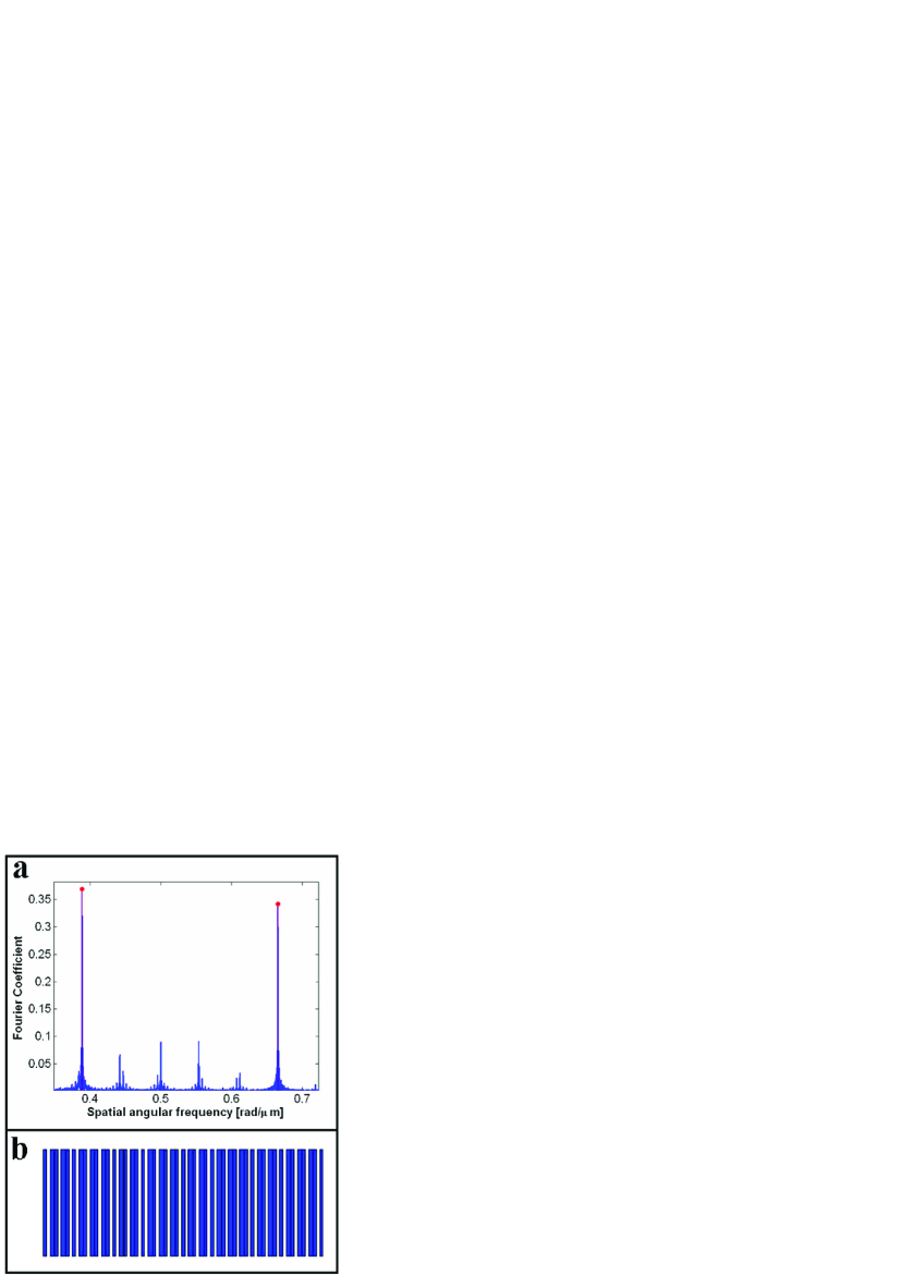
We implement the polarization switch using a LiNbO3 ferroelectric crystal at a temperature of centigrade. Because linear dispersion is different for the differently-polarized beams, the mismatch vectors for the two processes are not equal, and are calculated using tabulated properties of LiNbO3 [28, 29] to be for the first process, and for the second process. Using a one-dimensional version of the dual-grid method [25] we calculate the sequence of two tiling vectors, of lengths and , that generates a one-dimensional quasicrystal with the desired wave vectors in its reciprocal lattice. The actual one-dimensional quasicrystal is realized by using strips of widths and , arranged in the direction according to the quasiperiodic sequence determined by the dual-grid method. We use numerical optimization to find the optimal duty cycles for the two strips. We find that the best efficiencies for the desired processes are obtained when using duty cycles of and for the and tiling vectors respectively. This means that one half of each strip is positively-poled and the other half negatively-poled, while the narrow strips are completely positively-poled. A section of the resulting one-dimensional photonic quasicrystal is shown in Fig. 1(b). For a single process the best efficiency is achieved with a periodic nonlinear photonic crystal with a duty cycle for its single tile. In that case the relevant Fourier coefficient has the value of . This value is comparable to twice the Fourier coefficients at the required mismatch vectors of the polarization-switch device, shown in Fig. 1(a). However here we phase-match two processes simultaneously.
2.2 Two dimensional implementation
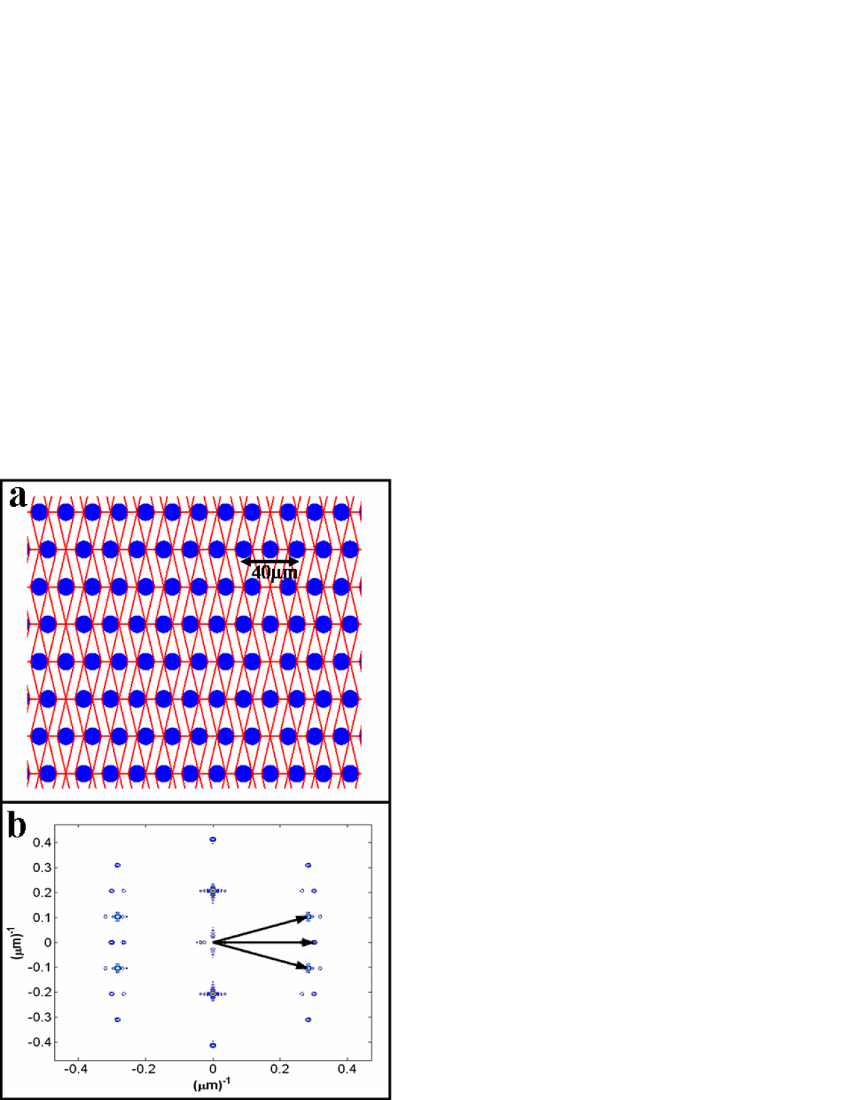
Next we demonstrate the versatility of our approach by designing a multi-directional second harmonic generator. This is a two-dimensional non-collinear device that takes three beams of wavelength 1550nm, propagating at angles of and , and generates three output beams at the same directions at twice the input frequency. Using Stoichiometric LiTaO3 and operating at centigrade, the magnitude of the mismatch vectors, for all three processes, is calculated [30] to be . The required two-dimensional photonic quasicrystal must clearly be symmetric with respect to the propagation direction of the input beam. Using a two-dimensional version of the dual-grid method [8], we find that it is generated by three tiling vectors, given in polar coordinates by , , and . This yields two types of tiles—a rhombus whose edges are 31.31 long, and a parallelogram whose edges are 31.31 and 7.54 long, the latter appearing in two mirror-related orientations.
For ease of fabrication we limit ourselves to decorating the center of each tile with a positively-polarized circle, leaving the remaining background negatively-polarized. We employ numerical optimization only for determining the radii of the circles for the different tiles. We find that the best efficiencies for the desired processes, with the largest magnitudes of the relevant Fourier coefficients, are obtained for using a maximally-inscribed circle within the rhombic tile, and using no circles within the parallelograms. An image of the decorated tiling, as designed by our procedure, is shown in Fig. 2(a). The calculated spectrum of the device is shown in Fig. 2(b). The reciprocal lattice vectors that phase match the three processes are indicated in this figure. The calculated magnitudes of the Fourier coefficients for the three mismatch vectors are and for the and processes respectively.
3 Physical realization of the cut and project method
We have recently described an alternative scheme applicable to collinear devices [31], in which one generates the required 1-dimensional photonic quasicrystal by a process that could be thought of as a physical realization of the cut-and-project method [32, 33]. Here we wish to elucidate some of its geometric features, and by doing so to emphasize its advantage for producing tunable devices. The reader, interested in actual implementation details of this scheme, is kindly referred to Ref. [31]. The basic idea is to fabricate a two-dimensional periodic crystal and employ the cut-and-project method to obtain a one-dimensional quasiperiodic crystal, capable of phase matching two independent collinear frequency-conversion processes. The cut is realized by taking advantage of the fact that the input beam is not an idealized plane wave of infinite transverse extent but actually has a finite width , for example with a Gaussian profile. Thus, the interaction of the beam with the nonlinear medium is restricted to a strip-like region of width along the propagation direction of the beam. Only those lattice sites of the two-dimensional crystal that fall within this strip in the transverse, or perpendicular (), direction contribute to the phase matching, and are effectively “projected” onto a one-dimensional quasicrystal along the propagation, or parallel (), direction.
The Fourier transform of the original 2-dimensional periodic crystal contains Bragg peaks at wave vectors that form a periodic reciprocal lattice. As we know from the cut-and-project method, the Fourier transform of the strip-like interaction region is 1-dimensional. Each 2-dimensional Bragg peak at wave vector gives rise to a 1-dimensional Bragg peak at the parallel component of the original wave vector, whose intensity depends on the perpendicular component of the same 2-dimensional wave vector. Because the Fourier transform of a Gaussian is also a Gaussian, if for example the beam has a Gaussian profile and we ignore any spreading of this profile as it propagates, then the dependence on is a simple Gaussian. Thus, given a pair of collinear mismatch wave vectors, one simply needs to find the appropriate angle with which to cut through the two-dimensional structure, so as to obtain two parallel projections with the required mismatch values, preferably of wave vectors with a small component. Thus, even with a prefabricated two-dimensional periodic crystal, one has the ability to tune the device by varying the cut angle through the crystal, enabling the use of one device for different combinations of frequency conversion processes.
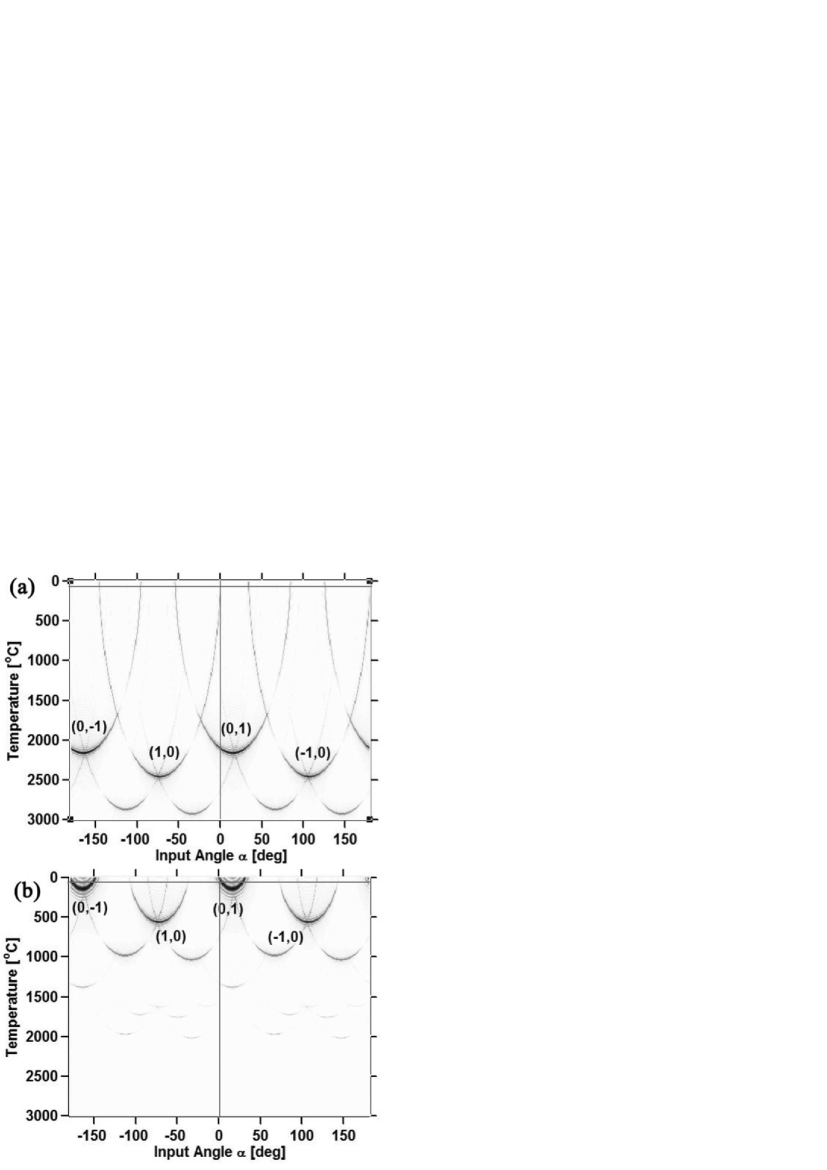
To illustrate how this approach can be used, we consider a nonlinear photonic crystal built upon an oblique periodic lattice, defined by the primitive vectors and , by associating a positively-poled circular motif of radius with every lattice point. We wish to phase match two collinear second harmonic generation processes of fundamental beams with wavelengths 1550nm and 1047.5nm. If we use stoichiometric LiTaO3 and operate at room temperature the phase mismatch values are calculated to be [30] and , respectively. By varying the operating temperature we can change the required mismatch wave vectors, and by selecting the propagation direction of the input beams we can vary the projected components. A simulation of all possible combinations of temperature and propagation angles that satisfy the phase matching conditions for the two processes is shown in Fig. 3. The simulation was carried out for an interaction length of 1mm and a -wide square-shaped beam profile. Darker shades correspond to higher efficiencies. Each parabola corresponds to a given reciprocal lattice vector of the two-dimensional crystal. The apex of the parabola corresponds to phase-matching using the whole reciprocal lattice vector (), while the other parabola points correspond to projection-based phase matching (). The intersection of the straight lines is the desired working point of this device at room temperature, where both processes are phase-matched simultaneously.
Acknowledgment
This research is funded by the Israel Science Foundation through grants 960/05 and 684/06.
References
- Shechtman et al. [1984] D. Shechtman, I. Blech, D. Gratias, and J. W. Cahn, Phys. Rev. Lett. 53, 1951 (1984).
- Dubois [2005] J.-M. Dubois, Useful Quasicrystals (World Scientific, Singapore, 2005).
- Lifshitz [2003] R. Lifshitz, Foundations of Physics 33, 1703 (2003).
- Jin et al. [1999] C. Jin, B. Cheng, B. Man, Z. Li, D. Zhang, S. Ban, and B. Sun, Appl. Phys. Lett. 75, 1848 (1999).
- Zoorob et al. [2000] M. E. Zoorob, M. D. B. Charlton, G. J. Parker, J. J. Baumberg, and M. C. Netti, Nature 404, 740 (2000).
- Mermin and Lifshitz [1992] N. D. Mermin and R. Lifshitz, Acta Cryst. A 48, 515 (1992).
- Lifshitz [1996] R. Lifshitz, Physica A 232, 633 (1996).
- Lifshitz et al. [2005] R. Lifshitz, A. Arie, and A. Bahabad, Phys. Rev. Lett. 95, 133901 (2005).
- Lifshitz [2007] R. Lifshitz, Z. Kristallogr. 222, 313 (2007).
- Fejer et al. [1992] M. M. Fejer, G. A. Magel, D. H. Jundt, and R. L. Byer, IEEE Journal of Quantum Electronics 28, 2631 (1992).
- Armstrong et al. [1962] J. A. Armstrong, N. Bloembergen, J. Ducuing, and P. S. Pershan, Physical Review 127, 1918 (1962).
- Freund [1968] I. Freund, Phys. Rev. Lett. 21, 1404 (1968).
- Bloembergen and Sievers [1970] N. Bloembergen and A. J. Sievers, Appl. Phys. Lett. 17, 483 (1970).
- Zhu et al. [1997] S.-N. Zhu, Y.-Y. Zhu, and N.-B. Ming, Science 278, 843 (1997).
- Fradkin-Kashi et al. [2001] K. Fradkin-Kashi, A. Arie, P. Urenski, and G. Rosenman, Phys. Rev. Lett. 88, 023903 (2001).
- Berger [1998] V. Berger, Phys. Rev. Lett. 81, 4136 (1998).
- Broderick et al. [2000] N. G. R. Broderick, G. W. Ross, H. L. Offerhaus, D. J. Richardson, and D. C. Hanna, Phys. Rev. Lett. 84, 4345 (2000).
- Bratfalean et al. [2005] R. T. Bratfalean, A. C. Peacock, N. G. R. Broderick, K. Gallo, and R. Lewen, Optics Letters 30, 424 (2005).
- Ma et al. [2005] B. Ma, T. Wang, Y. Sheng, P. Ni, Y. Wang, B. Cheng, and D. Zhang, Applied Physics Letters 87, 1103 (2005).
- de Bruijn [1981] N. de Bruijn, Proc. K. Ned. Akad. Wet., Ser. A 84, 39 (1981).
- Gähler and Rhyner [1986] F. Gähler and J. Rhyner, J. Phys. A: Math. Gen. 19, 267 (1986).
- Rabson et al. [1988] D. A. Rabson, T.-L. Ho, and N. D. Mermin, Acta Cryst. A 44, 678 (1988).
- Rabson et al. [1989] D. A. Rabson, T.-L. Ho, and N. D. Mermin, Acta Cryst. A 45, 538 (1989).
- Senechal [1995] M. Senechal, Quasicrystals and Geometry (Cambridge University Press, 1995).
- Bahabad et al. [2007] A. Bahabad, N. Voloch, A. Arie, and R. Lifshitz, J. Opt. Soc. Am. B 24, 1916 (2007).
- Saltiel and Deyanova [1999] S. Saltiel and Y. Deyanova, Optics Letters 24, 1296 (1999).
- Stegeman et al. [1996] G. I. Stegeman, D. J. Hagan, and L. Torner, Opt. Quantum Electron. 28, 1691 (1996).
- Jundt [1997] D. H. Jundt, Optics Letters 22, 1553 (1997).
- Edwards and Lawrence [1984] G. J. Edwards and M. Lawrence, Opt. Quantum Electron. 16, 373 (1984).
- Bruner et al. [2003] A. Bruner, D. Eger, M. B. Oron, P. Blau, M. Katz, and S. Ruschin, Optics Letters 28, 194 (2003).
- Bahabad et al. [2007] A. Bahabad, N. Voloch, A. Arie, A. Bruner, and D. Eger, Phys. Rev. Lett. 98, 205501 (2007).
- Elser [1985] V. Elser, Phys. Rev. B 32, 4892 (1985).
- Duneau and Katz [1985] M. Duneau and A. Katz, Phys. Rev. Lett. 54, 2688 (1985).