]Received
Impact of in-plane currents on magnetoresistance properties of an exchange-biased spin-valve with insulating antiferromagnetic layer
Abstract
The impact of in-plane alternating currents on the exchange bias, resistance, and magnetoresistance of a Co85Fe15/Ni0.85Co0.15O/Co85Fe15/Cu/Co85Fe15 spin-valve is studied. With increasing current, the resistance is increased while the maximum magnetoresistance ratio decreases. Noticeably, the reversal of the pinned layer is systematically suppressed in both field sweeping directions. Since Ni0.85Co0.15O oxide is a good insulator, it is expected that the ac current flows only in the Co85Fe15/Cu/Co85Fe15 top layers, thus ruling out any presence of spin-transfer torque acting on the spins in the antiferromagnetic layer. Instead, our measurements show clear evidences for the influence of Joule heating caused by the current. Moreover, results from temperature-dependent measurements very much resemble those of the current dependence, indicating that the effect of Joule heating plays a major role in the current-in-plane spin-valve configurations. The results also suggest that spin-transfer torques between ferromagnetic layers might still exist and compete with the exchange bias at sufficiently high currents.
pacs:
73.50.Jt, 75.47.De, 75.70.Cn, 85.75.-dA current flowing through two nanoscale ferromagnets tends to align their magnetic moments by a torque induced by the transfer of spin angular momentum of the electrons polarized by one ferromagnet to the other Slonczewski ; Berger . The technique based on this phenomenon for controlling the state of ferromagnetic layers in spin-valve Tsoi ; Myers ; Sun ; Albert ; Aoshima ; Krivorotov and magnetic tunneling junction (MTJ) Huai ; Fuchs ; Yoshikawa ; Assefa structures has many advantages expected to be useful in magnetic random access memory (MRAM) technology. It has been reported recently Nunez ; Wei ; Urazhdin ; Tang that a current could also induce a torque on the staggered moment of an antiferromagnet and switch the direction of the exchange-bias field at the antiferromagnet/ferromagnet interface. The switching of an antiferromagnet (and therefore of the exchange bias field) even seems to appear at a lower current density than for switching a ferromagnet Tang .
Núñez et al. Nunez proposed a theory based on a model of 1D sandwich structure consisting of two antiferromagnets separated by a paramagnetic spacer and predicted that currents could also alter the micromagnetic state and induce a spin-transfer torque that acts on the staggered moment of an antiferromagnet. Importantly, the authors found that the critical current for switching an antiferromagnet is smaller than the typical value for a ferromagnet because the spin transfer torques act cooperatively throughout the entire antiferromagnet together with the absence of shape anisotropy. Wei et al. Wei later reported a variation of exchange bias by a high-density dc current injected from a point contact into a spin valve; the exchange bias can increase or decrease depending upon the current direction. The authors explained their results in favor of the theory proposed by Núñez et al. Nunez , i.e., electrons flowing from the ferromagnet into the antiferromagnet induce torques on moments in the antiferromagetic matrix, altering its magnetic configuration and favoring the parallel alignment of moments at the ferromagnet/antiferromagnet interface, and therefore increase the exchange-bias field, whereas electrons flowing in the opposite direction tend to have the opposite effect. More convincing evidences for the effects of spin polarized currents on an antiferromagnet in a spin-valve structure have been also reported very recently by Urazhdin and Anthony Urazhdin .
In general, spin transfer or spin torque between the ferromagnetic layers in a spin-valve (or MTJ) structure is expected when the current flows perpendicular to layer planes (CPP) Slonczewski . This also applies to the case of antiferromagnetic spin torque because the current is needed to pass through the antiferromagnetic layers Nunez ; Wei . Interestingly, Tang et al. Tang have reported that dc currents flowing in the layer planes (CIP) of an exchange-biased spin-valve can systematically change the exchange bias. The authors also explained their results based on an assumption that, together with the influence of the current-induced field, electrons flowing into the antiferromagnetic layer from the ferromagnetic one induce torques on the moments in the antiferromagnet. In the present work, to avoid electrons flowing into the antiferromagnetic layer in CIP measurements, we fabricated a spin-valve structure with an extremely high resistance antiferromagnetic layer. However, we still observe clear and systematic suppressions of the reversals of the pinned layer with increasing current. Our results suggest that the effect caused by Joule heating is significant and local spin torques between ferromagnetic layers might still exist even in CIP configurations.
The samples with a basic structure of FeCo(2.4)/NiCoO(40)/FeCo(3.0)/Cu(3.8)/FeCo(4.5) (here, FeCo = Fe15Co85, NiCoO = Ni0.85Co0.15O, and all the thicknesses are in nm) were fabricated using a magnetron sputtering system (EDWARD AUTO 306) equipped with 3 targets, a dc and an rf source in the chamber with a base vacuum of mbar. The FeCo and Cu layers were deposited in Ar gas pressures of mbar and mbar, respectively. The NiCoO antiferromagnetic layer was deposited from a Ni85Co15 target in a mbar of a flowing mixture of Ar and 20% O2. The resistance of our NiCoO films is so high, probably more than 100 M, that we were unable to measure it accurately. An external magnetic field of 500 Oe was aligned parallel to the substrate plane during the deposition processes to create an initial exchange bias. The quality of the films was examined by x-ray diffraction, energy-dispersive x-ray spectroscopy, magnetization, and conductance techniques. Resistance () and magnetoresistance [] were measured on a sample using the standard four-probe method by a Quantum Design PPMS 7100 with an ac current () at a frequency Hz. The current was set to flow only during the duration time of measurement reading ( s was applied for all measurements except those specified in Fig. 2). In all the measurements, the external magnetic field (), the sample’s exchange-bias and the injected current were always aligned in the same axis. Unless otherwise specified in the temperature-dependent measurements (Fig. 4), all the data were measured at K.
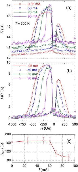
Representative and curves are presented in Figs. 1(a) and 1(b), respectively. The reversal field of the free layer seems not to be affected while that of the pinned layer (in both field sweeping directions) is substantially suppressed. The maximum on the branch is nearly erased at mA when the reversal of the pinned layer occurs at a magnetic field too close to that of the free layer. It is remarkable that the results in Fig. 1 just resemble those previously observed in spin-valves having a metallic antiferromagnetic layer where current flows to induce torques on its magnetic moments therefore leading to a change of the exchange bias Wei ; Tang . In our case, since the in-plane current is confined to flow only in the FeCo(3.0)/Cu(3.8)/FeCo(4.5) top layers, there would be no such current-induced spin torques in the antiferromagnetic layer. Moreover, the suppressions of the reversals of the pinned layer in our spin-valve may even not reflect a variation of exchange bias. Since an exchange bias field causes a displacement of the or curves to its reverse direction, a decrease of the exchange bias should therefore always shift both of the reversals of the pinned layer along the exchange bias direction. Our results in Fig. 1 show the difference: with increasing current, the reversals of the pinned layer on the and branches are oppositely shifted. In fact, by determining the exchange bias field as with and are the fields at which the pinned layer reverses completely on the and branches, respectively, we obtained values of 170 Oe that is almost unchanged for currents up to 60 mA, above which the exchange bias starts to decrease rapidly [Fig. 1(c)]. This is a clear evidence that the changes of and are not related to a change of exchange bias, at least for currents up to 60 mA, which is equivalent to a current density of A/cm2 flowing through the three top layers (note that this current density is about more than 3 orders higher than the switching current reported in Ref. Tang for an antiferromagnet and still far below the typical level for switching a ferromagnet). The magnetic field generated by the ac current would cause an oscillation of the actual field direction applied on the layers. If that oscillation is strong enough to affect the reversals of the pinned layer, it should have already affected the free layer that is more susceptible to magnetic field with a coercive field much smaller than both and . Clearly, our results do not support this reason.
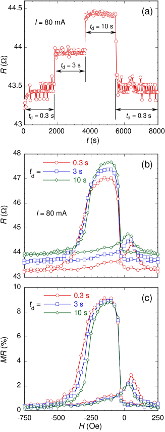
The increases of resistance in both parallel and antiparallel states with higher currents would suggest a possibility of Joule heating although the current injection is turned on only for a short duration time for resistance reading. The curves in Fig. 1 were measured with s and the reading interval was kept unchanged for all the measurements. Since the sample would take an amount of time much longer than to reach thermal equilibrium, an increase of is thus expected to raise the sample’s actual temperature that in turn increases the resistance of the metallic layers. This possibility is verified in Figs. 2(a) and 2(b) where an increase (decrease) of resistance is always observed corresponding to an increase (decrease) of . Figure 2(c) also shows that the reversals of the pinned layer are monotonically suppressed with increasing , just as increasing . Obviously, the effects caused by current amplitudes and duration times are qualitatively similar.
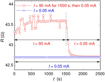
Another indication of the current heating effect is displayed in Fig. 3 where resistance data from two measurements are recorded with time. In one measurement, was measured at mA and is considered as a non-heating curve. On the other measurement, mA was applied for the first 1500 s and then the current was abruptly switched to 0.05 mA causing a change of resistance towards the reference non-heating curve. This observation corroborates the results in Fig. 1(a) that a higher current gives a higher resistance value. Another noticeable feature recognized in Fig. 3 is that when the current mA was applied (at s) and switched to 0.05 mA (at s), correspondingly to a heating and a cooling process respectively, the resistance takes a few minutes to reach the equilibrium values.
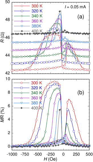
As we have discussed, our results indicate that current heating plays an important role in varying the magnetoresistance behavior of the CIP spin-valve. In order to figure out whether the current can cause effects in addition to the Joule heating, we carried out measurements at different temperatures from 300 K to 400 K. The influence of temperature, as shown in Fig. 4, is qualitatively the same as that of current amplitude (Fig. 1) or duration time (Fig. 2) except that the data are much less noisy. A comparison of the results in Fig. 1 and Fig. 4 reveals an interesting feature: heating is not the only direct effect caused by the current. The curves at K ( mA) and mA ( K) show similar parallel and antiparallel resistances ( and , respectively) but the exchange bias field is more suppressed under the influence of current ( Oe at mA and K while Oe at mA and K). On the other hand, the curve at mA ( K) reveals a nearly similar Oe as the K ( mA) curve, but the resistance values are smaller in both parallel and antiparallel states (43 and 46.9 compared to 43.9 and 47.7 , respectively). This implies that the resistance (or exchange bias) is less raised (or more suppressed) by currents than by purely temperature. We attribute this behavior to a spin transfer between the two ferromagnetic layers. Even in a CIP configuration, due to scattering processes, electrons are not confined to flow in one specific layer but they still weave through and transfer spin angular momentum between the two ferromagnetic layers. Such a spin transfer of electrons in CIP configurations may not be as efficient as in CPP configurations, but contributes to reducing spin scattering (thus lowering resistance) and have an affection on the reversal of the pinned layer. It is also possible that, at sufficiently high currents, the exchange bias is directly affected by electron scattering at the interface between the pinned ferromagnetic and the antiferromagnetic layer.
In conclusion, we have proved that Joule heating could play a major role in the impact of in-plane current on the magnetotransport properties of a spin-valve. The reversals of the pinned layer are suppressed even at low currents when the exchange bias is not yet affected, probably by a decrease of its coercive force with temperature. Not only do they generate heat, in-plane currents also induce spin transfers between the ferromagnetic layers that in turn compete with the exchange bias.
A part of this work was performed using facilities of the State Key Labs (IMS, VAST, Vietnam). This work was also supported by MOST/KOSEF through Quantum Photonic Science Research Center at Hanyang University (Seoul, Korea). Two of us thank the University of Virginia for support.
References
- (1) J. C. Slonczewski, J. Magn. Magn. Mater. 159, L1 (1996).
- (2) L. Berger, Phys. Rev. B 54, 9353 (1996).
- (3) M. Tsoi, A. G. M. Jansen, J. Bass, W.-C. Chiang, M. Seck, V. Tsoi, and P. Wyder, Phys. Rev. Lett. 80, 4281 (1998).
- (4) E. B. Myers, D. C. Ralph, J. A. Katine, R. N. Louie, and R. A. Buhrman, Science 285, 867 (1999).
- (5) J. Z. Sun, J. Magn. Magn. Mater. 202, 157 (1999).
- (6) F. J. Albert, J. A. Katine, R. A. Buhrman, and D. C. Ralph, Appl. Phys. Lett. 77, 3809 (2000).
- (7) K.-I. Aoshima, N. Funabashi, K. Machida, Y. Miyamoto, N. Kawamura, K. Kuga, N. Shimidzu, and F. Sato, Appl. Phys. Lett. 91, 052507 (2007).
- (8) I. N. Krivorotov, D. V. Berkov, N. L. Gorn, N. C. Emley, J. C. Sankey, D. C. Ralph, and R. A. Buhrman, Phys. Rev. B. 76, 024418 (2007).
- (9) Y. Huai, F. Albert, P. Nguyen, M. Pakala, and T. Valet, Appl. Phys. Lett. 84, 3118 (2004).
- (10) G. D. Fuchs, N. C. Emley, I. N. Krivorotov, P. M. Braganca, E. M. Ryan, S. I. Kiselev, J. C. Sankey, D. C. Ralph, R. A. Buhrman, and J. A. Katine, Appl. Phys. Lett. 85, 1205 (2004).
- (11) M. Yoshikawa, T. Ueda, H. Aikawa, N. Shimomura, E. Kitagawa, M. Nakayama, T. Kai, K. Nishiyama, T. Nagase, T. Kishi, S. Ikegawa, and H. Yoda, J. App. Phys. 101, 09A511 (2007).
- (12) S. Assefa, J. Nowak, J. Z. Sun, E. O Sullivan, S. Kanakasabapathy, W. J. Gallagher, Y. Nagamine, K. Tsunekawa, D. D. Djayaprawira, and N. Watanabe, J. App. Phys. 102, 063901 (2007).
- (13) S. Krause, L. Berbil-Bautista, G. Herzog, M. Bode, R. Wiesendanger, Science 317, 1537 (2007).
- (14) A. S. Núñez, R. A. Duine, P. Haney, and A. H. MacDonald, Phys. Rev. B 73, 214426 (2006).
- (15) Z. Wei, A. Sharma, A. S. Nunez, P. M. Haney, R. A. Duine, J. Bass, A. H. MacDonald, and M. Tsoi, Phys. Rev. Lett. 98, 116603 (2007).
- (16) S. Urazhdin and N. Anthony, Phys. Rev. Lett. 99, 046602 (2007).
- (17) X.-L. Tang, H.-W. Zhang, H. Su, Z.-Y. Zhong, and Y.-L. Jing, Appl. Phys. Lett. 91, 122504 (2007).