High Performance Cooperative Transmission Protocols Based on Multiuser Detection and Network Coding
Abstract
Cooperative transmission is an emerging communication technique that takes advantage of the broadcast nature of wireless channels. However, due to low spectral efficiency and the requirement of orthogonal channels, its potential for use in future wireless networks is limited. In this paper, by making use of multiuser detection (MUD) and network coding, cooperative transmission protocols with high spectral efficiency, diversity order, and coding gain are developed. Compared with the traditional cooperative transmission protocols with single-user detection, in which the diversity gain is only for one source user, the proposed MUD cooperative transmission protocols have the merit that the improvement of one user’s link can also benefit the other users. In addition, using MUD at the relay provides an environment in which network coding can be employed. The coding gain and high diversity order can be obtained by fully utilizing the link between the relay and the destination. From the analysis and simulation results, it is seen that the proposed protocols achieve higher diversity gain, better asymptotic efficiency, and lower bit error rate, compared to traditional MUD schemes and to existing cooperative transmission protocols. From the simulation results, the performance of the proposed scheme is near optimal as the performance gap is dB for average bit error rate (BER) and dB for average BER , compared to two performance upper bounds.
I Introduction
Cooperative transmission [1, 2] takes advantage of the broadcast nature of wireless channels to improve data transmission through cooperation among network nodes. Notably, relay nodes can be employed as virtual antennas for a source node, so that the multiple input multiple output (MIMO) technology can be exploited even with single-antenna terminals. Recent work has explored cooperative transmission in a variety of scenarios, including cellular networks [3], ad hoc/sensor networks [4, 5, 6], WiFi/WiMax [7] and ultra-wideband [8]. One drawback of existing cooperative transmission schemes is a consequent reduction of spectral efficiency due largely to the fact that most such techniques require orthogonal channels for the transmissions of cooperating nodes111It is worth mentioning that the spectral efficiency in the cooperative transmission literature is defined as the number of orthogonal channels required for direct transmission divided by the overall number of channels for both direct transmission and relaying. This definition is different from that of spectral efficiency typically used in the adaptive modulation literature [20].. This requirement is limiting, as many wireless networks, such as 3G cellular networks, cannot provide orthogonal channels.
In this paper, we consider cooperative transmission protocols for networks that do not require orthogonality among the signaling channels of the nodes in the network. Such a scenario naturally motivates the use of multiuser detection (MUD) [9] to mitigate the interference caused by non-orthogonal signaling. The performance of MUD is generally good when interfering users have significantly different link conditions from one another. In traditional MUD, the link conditions are determined by users’ locations and channel gains, which are not controllable by the designer. However, with cooperative transmission, we have the opportunity to optimize such conditions by deciding which relay will retransmit which user’s information so that the selected users’ link conditions can be optimized for overall system performance. A link level analysis for MUD over cooperative transmission can be found in [10].
Recently [11] has considered the joint optimization of MIMO systems with MUD. However, unlike MIMO MUD in which all information from different antennas can be obtained without limitation, in cooperative communications the information transmission between the relay (i.e., the virtual antenna) and the destination is restrained by a lossy relay-destination wireless link. To overcome this limitation, network coding [12, 13] provides a potential solution. The core notion of network coding is to allow mixing of data at intermediate network nodes to improve the overall reliability of transmission across the network. A destination receives these coded data packets from various nodes and deduces from them the messages that were originally intended for that destination. In [14], it is seen that information exchange can be efficiently performed by exploiting network coding and the broadcast nature of the wireless medium. In cooperative transmission, the relay can be viewed as an intermediate network node. In [15], the network coding gains of various cooperative diversity protocols are examined in detail. In this paper, we consider the situation in which MUD is employed at the relays, so that a relay can obtain information from various users and then use network coding by mixing multiple users’ data and transmitting coded information through the limited relay-destination link. In other words, MUD provides an environment for deploying network coding, and network coding can achieve substantial coding gain and high diversity to overcome the limitations of the relay-destination link.
In particular, we propose two cooperative transmission protocols that utilize MUD and network coding. In the first protocol, realizing that improvement in one user’s detection can help the detection of the other users in certain types of multiuser detectors (e.g., interference cancelers), we decide which relays to use and whose information the selected relays will retransmit such that the overall system performance can be optimized at the sink node. In the second protocol, we assume the relays are equipped with MUD. Then the selected users’ information is coded by network coding and is relayed to the base station. At the base station, the coding gain is not only realized for the selected users but also for the other users because of MUD. Moreover, we develop two performance upper bounds to evaluate the proposed schemes. Practical implementation issues are also discussed. From both analytical and simulation results, it is seen that the proposed protocols achieve higher diversity and coding gains, better asymptotic efficiency, and lower bit error rate (BER) than existing schemes without sacrificing spectral efficiency. The proposed scheme achieves performance less than 0.12dB away from the performance upper bounds when the average BER equals , and 1.04dB when BER equals .
This paper is organized as follows: In Section II, system models are given for cooperative transmission and MUD in a network consisting of a source node (e.g., a mobile terminal), a sink node (e.g., a base station or access point) and a set of relays. In Section III, the two above-mentioned protocols are constructed. In Section IV, the properties of the proposed protocols are analyzed. Simulation results are shown in Section V, and conclusions are drawn in Section VI.
II System Model
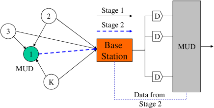
We consider an uplink synchronous code-division multiple-access (CDMA) system with Gaussian ambient noise222Note that asynchronous CDMA can be treated similarly.. There are synchronous uplink users (i.e., terminals) each with a single antenna. Here the number of users is no more than the number of available CDMA codes. Among these terminals, can serve as relays. This system model is illustrated with in Figure 1. At the first transmission stage, all users except the relays send information, and the relays listen (and perform MUD if they have the ability). At the second stage, the other users send their next information signals, while the relays send a certain user’s information or the networking-coded information from the results of MUD applied at the first stage. In the sink node, which for convenience we will refer to as the a base station, all of the other users’ information from the first stage is delayed by one time slot and jointly detected with the information sent by the relays at the second stage. Since the users cannot transmit and receive at the same time or on the same frequency, to relay once costs at least two time slots for listening and relaying. So the spectral efficiency is , and thus when the number of users is much larger than the number of relays the spectral efficiency approaches one. On the other hand, in the traditional cooperative transmission with one-relay and one-source pair, . In this case, the spectral efficiency is .
We denote by the group of relay terminals, and by the group of terminals that are listening and will serve as relays in the next time slot333This is because of half duplex.. Define the set for all users. In the first stage, the received signal at the base station can be expressed as
| (1) |
and at user , who is listening and preparing for a relay in the next time slot, as
| (2) |
where is the received amplitude of the user’s signal at the base station, is the received amplitude of the user’s signal at relay , is the data symbol transmitted by the user, is the relayed bit, is the unit-energy signature waveform ( i.e. Pseudo-random code) of the user, and are the normalized white Gaussian noise, and and are the background noise power densities. For simplicity, we assume , although the more general case is straightforward.
The received signal vectors at the base station and at the relay after processing by a matched filter bank can be written as
| (3) |
and
| (4) |
where R is the signal cross-correlation matrix, whose elements can be written as
| (5) |
with the inverse of the data rate, , , , and consists of symbols of direct-transmission, relay, and listening users. In particular, is the direct-transmission symbol, is the relay symbol, and the listening relay has zero to transmit due to the half duplex assumption.
From the cooperative transmission perspective, in the first stage user transmits its signal directly to the base station, and user listens. In the second stage, the users listening in the first stage become relays (set ) and relay the information to the base station. At the base station, the information at the first stage is delayed by one time slot and then is combined with the information at the second stage.
In this paper, we will investigate the BER performance of MUD under cooperative transmission. Specifically, we will consider optimal MUD and the successive cancellation detector, which is one type of decision-driven MUD.
As pointed out in [9], there is no explicit expression for the error probability of the optimal multiuser detector, and bounds must be used. A tight upper bound is provided by the following proposition from [9].
Proposition 1
The BER of the user for optimal MUD is given by
| (6) |
where is a possible error vector for user , and . is the number of nonzero elements in , and is the subset of indecomposable vectors. (See [9] for details.)
For the successive cancellation detector, a recursive approximation for the error probability is given by the following proposition[9].
Proposition 2
The BER of the user for successive cancellation is given approximately by
| (7) |
where is the spreading gain. The cancellation order is that user is detected first, then user and so on.
In the denominator in the argument of the -function in (7), if errors exist for the previously detected users, the interference caused to the latter detected users is at four times the power level of the original signal. So if the error probabilities of the previously detected users can be reduced by cooperative transmission, the overall performance can be greatly improved.
Notice that the BERs in (6) and (7) are functions of the users’ received amplitudes. These in turn are functions of the user locations and the network topology, which are fixed in traditional multiuser channels. As will be shown later, in our proposed schemes, we have the freedom to select which users will serve as relays and which users’ information to relay. This freedom allows us to modify the link qualities and achieve the optimal performance in terms of overall BER at the base station.
III Two Cooperative Transmission Protocols
In this section, we propose two cooperative transmission protocols. The first protocol seeks to exploit the fact that MUD can improve the reception of all signals because of the mitigation of interference from the strong ones. MUD is used in the base station, while at the relay single user detection is employed. The second protocol further exploits network coding in the relay to make full use of the relay-destination channel and to provide better coding gain and diversity gain. In this protocol, MUD is employed at both the base station and the relay.
III-A Protocol 1: Joint MUD and Cooperative Transmission
Suppose terminal is selected as the relay and it forwards user ’s information. At the base station, following a matched filter bank, maximal ratio combining (MRC) is used to combine the signals from these two terminals. Since optimal MUD and decision driven MUD algorithms are nonlinear, a closed-form expression for MRC is not available. In our analysis, we assume that some method, such as a threshold test [2] or cyclic redundancy check (CRC), is employed so that the potential relays and the base station can determine with some certainty whether or not the detected signals are correct. Instead of MRC before decoding, the final decision is based on the decoded signals in both stages. Thus, an error occurs only if the signals in both stages are wrong. So the probability of error can be written as
| (8) |
The error probabilities of data transmission from user to the base station, from user (i.e., the relay) to the base station, and from user to user are denoted as , , and , respectively. Notice that there is no need for MUD at the relays for the first protocol.
| 1. At Stage 1, the sources send packets, the base station stores |
|---|
| them, and the relays decode them. |
| 2. After Stage 1, the base station decides which users’ packets |
| are to be relayed according to (9). |
| 3. At Stage 2, using the feedback from the base station, the |
| relays forward the selected users’ information so as to |
| optimize the decoding. |
| 4. After Stage 2, two-stage combining and MUD are performed |
| at the base station. |
The issues to be considered here are which relays to select among the potential users (selecting ), and whose data to retransmit (selecting ). The performance index for system optimization is the overall BER. If only one relay is selected444For the multiple relay case, if no user’s information can be relayed more than once, the problem formulation is the same. Otherwise, we need to change (8). As a result, the searching space will increase exponentially with the number of relays. In that case, low complexity heuristics must be developed, which is beyond the scope of this paper., the problem formulation to minimize the overall BER can be written as
| (9) |
To optimize (9), we propose an algorithm shown in Table I. The basic idea is that the base station can know after Stage 1 which users’ links need to be improved so as to maximize the network performance. Moreover, the information of the relay such as and can also be feeded back to the base station. So the optimal parameter pair can be selected555Here we use the exhaustive search for the optimal pair. Some heuristic fast algorithms such as greedy solution can be easily constructed., and the corresponding information is sent. At the base station, the information sent at the first stage is stored and combined with the relay’s information at the second stage. Consequently, the performance of all users can be improved. The only control signaling required is to send information through a control channel to inform the corresponding relay which user’s information to forward.
III-B Protocol 2: With Consideration of Network Coding
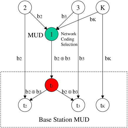
The second protocol seeks to exploit the fact that MUD in the base station and the relay provides a possible data-flow structure for jointly optimizing MUD and network coding. In Figure 2, we illustrate an example in which there are users and user is assigned as the relay. At the first stage, users through send their own information, while the base station and user listen. At the second stage, user sends the coded information (here , where is XOR function). Then the base station can improve the decoding of user and user . The performance gain is due to the network coding.
In general, we can formulate joint MUD and network coding as follows: As a relay, user selects a set of users , and then transmits , where . Notice that is a subset of all users that are successfully decoded at the first stage by user . At the base station, the user’s error probability is given by:
| (10) |
and
| (11) |
The first term in (III-B) represents the direct transmission error probability. The term in the parentheses of (III-B) represents the error probability from the relay using network coding. Successful transmission from the relay occurs only if, without network coding gain, all users in are decoded correctly by user , the transmission from user to the base station is correct, and all other users are correctly decoded at the base station. Notice that compared with (8), the error probability for a specific user might be worse. However, since in (III-B), multiple users’ BERs can be improved, the overall BER of the system can be further improved under careful optimization. The inequality in (11) holds since the cancellation of some successfully decoded users’ information can improve the other users’ decoding.
We need to select relay from the set of size , and the set which represent whose information should be relayed by user . So the general problem formulation for both Protocol 1 and Protocol 2 can be written as
| (12) |
The algorithm for Protocol 2 is similar to that of Protocol 1 except that, in Protocol 2, the relays transmit the network coded symbol in the second stage. Compared with the first protocol, Protocol 2 can improve more than one users’ signal strength at the base station in Stage 2. This is because several users’ information can be carried using network coding. However, if too many users’ information is coded with network coding, the error correction capability in the base station will be reduced. So there is a tradeoff on how many users’ information to be encoded. Moreover, Protocol 2 requires MUD at the relay which could be a mobile handset. Since this requirement increases the cost and power consumptions of relays, this could be an issue.
IV Performance Analysis
In this section, we first examine the diversity order and coding gain of the proposed protocols. Then, we give a performance upper bound using MIMO-MUD. Next, we study a special case for how the relay changes the asymptotic multiuser efficiency. Finally, we give an exact expression for a symmetric case.
IV-A Diversity Order and Cooperative MUD Gain
First we study the diversity order for the users whose information is relayed. Then we provide another performance gain metric, cooperative MUD gain, to quantify the additional gain to the other users.
For Protocol 1, the diversity order (i.e., the number of independently received signals) can be up to for the relayed user, while the remaining un-relayed users have diversity order . For Protocol 2, the diversity order for all users is up to . From the simulation results presented below, we see that the high diversity order can be achieved compared to a performance bound (which has been shown to have the high diversity order). Rigorous proof for the high diversity order of the proposed scheme is very difficult to achieve, due to the intractability of BER expressions for MUD detectors. However, we provide an intuitive analysis in the sequel.
For Protocol 1 after Stage 1, we order the received signals at the base station according to their SINRs, where user has the highest SINR (i.e. the lowest BER). We assume all relays select user ’s information to retransmit if the relay decodes it correctly. The reason to select user with the highest SINR is to limit error propagation in (7). The diversity order for user is since copies of user ’s information are transmitted via direct link and relay links and all those link responses are independent. Because only user ’s copy of the information at Stage 1 is retransmitted, the diversity order of the other users is still . If the relays select different users’ information to relay, the diversity orders of these users depend on how many relays retransmit their information.
For Protocol 2, at the second stage the relays retransmit the following information
| (13) |
Here we assume includes all users, i.e., .
When the SINRs are sufficiently high (i.e. the multiple access interference is sufficiently low), the channels between the senders and relays approach ideal links. All direct links are independent and approach ideal links. For example in Figure 2, at the second stage after network decoding, will receive two copies of from direct transmission and from if has sufficiently small BER. In a generalized case, if the size of is , the diversity order for every user is from the relays and the direct link, when the SINRs are sufficiently high. Another interpretation is that when the SINRs become sufficiently large, the links between the relays and base station are sufficiently good. Consequently, the cooperative system with Protocol 2 is equivalent to MIMO MUD system with diversity order of .
On the other hand, if the diversity orders of certain users increase, the remaining users have better performance since their interference (user ’s signal) can be more successfully cancelled. To quantify the performance gain, we define the following quantity.
Definition 1
The cooperative MUD gain is defined as the SINR improvement ratio for the remaining users, due to the link improvement gained when the other users use cooperative MUD receivers.
For the successive cancellation multiuser detector of Protocol 1, we have
| (14) |
where is user ’s new BER and . If , the MUD gain can be significantly large. For the MUD gains of other users, we can calculate recursively.
For the optimal MUD of Protocol 1, for each possible error vector , the MUD gain can be approximated by
| (15) |
where is the improvement of the user’s signal strength and is the same as matrix A (defined in (3)) except that is replaced by . Notice that the channel improvement is upper bounded by that of MRC of direct transmission and relay transmission.
For the successive cancellation detector of Protocol 2, the MUD gain for the user with the second strongest link is the same as (14). For the remaining users, the MUD gain is larger since higher diversity order for all the users with larger SINR reduces the error probabilities, which affect the noise of this user. For the optimal MUD of Protocol 2, the elements of the matrix A increase (i.e., every link is enhanced with diversity ). So the BER for each possible error vector is also reduced and so is the overall BER.
IV-B Performance Bounds
We develop two performance bounds for the proposed cooperative transmission protocol with MUD. First, in MIMO MUD [11], we can assume infinite bandwidth between the relays and the base station. The performance under these circumstances gives us an upper bound for Protocol 2 of cooperative transmission MUD. Here we assume that the relay is perfectly connected to the destination, and that combination is performed after decoding. Decoding error occurs when the direct transmission and all of the source-relay links fail, i.e. for the high SINR case we have the first performance upper bound given by
| (16) |
where is the BER for direct transmission and is the transmission from user to relay . For MIMO MUD, the diversity order is .
Second, if we assume that the links between the source and relays are perfect and the SINRs for the two stages can be directly added before the decoding, we can obtain another performance upper bound for Protocol 1. If we assume all relays retransmit user ’s information, for the successive cancellation detector, we can derive a bound in the following recursive form:
| (17) |
Notice that the interference terms from the stronger users in the denominator still have amplitudes ’s, since the interference comes from the first stage of the cooperative transmission. For optimal MUD, the second performance upper bound can be obtained by setting .
Another interpretation of the above two bounds is as follows. For the bound in (16), all relays are located close to the base station so that the relay-destination links are sufficiently good. For the bound in (17), all source users and relays are assumed to be closely located in a cluster away from the base station. The source-relay links are assumed to be perfect. In reality, the source nodes and relay nodes are located randomly. So the real performance is worse than the two performance upper bounds - i.e., the bounds may not be tight.
IV-C Asymptotic Multiuser Efficiency
In this subsection, we study a special case in which there are two users and one relay to investigate the performance improvement that results from using MUD. First, we review the definition of asymptotic multiuser efficiency.
Definition 2
The asymptotic multiuser efficiency is defined as
| (18) |
which quantifies the degradation in SINR suffered by a user due to the presence of other users in the channel.
Similarly to the second performance upper bound in the previous subsection, we make the approximations that the relay can always decode correctly and that the base station can use maximal ratio combining of the direct and relay transmissions. In this ideal case, the multiuser efficiency of optimal MUD can been expressed as
| (19) |
where is the cross-correlation, and , , and are the channel gains to the base station for user , user and the relay, respectively.
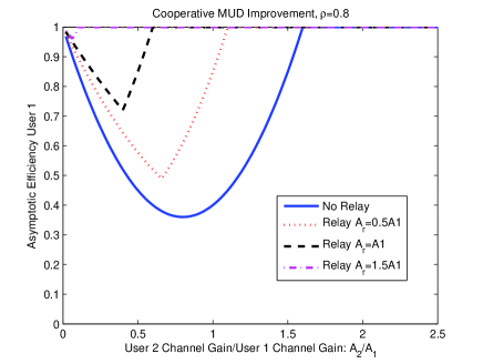
In Figure 3, we show the asymptotic multiuser efficiency with =1 and . The key idea here is that the asymptotic multiuser efficiency is bad when the ratio of and is around , but with the relay’s help this ratio can be changed so that the asymptotic multiuser efficiency can be greatly improved. We can see that when the relay is close to the destination (i.e. is large), the asymptotic multiuser efficiency can be almost . This is because the relay can always improve the stronger user’s link so that the difference is even larger. Consequently, the multiuser efficiency can be greatly improved. When the relay moves far away from the destination, the asymptotic multiuser efficiency improvement is reduced, since decreases and the relay is less effective. We note that this comparison is unfair, since the bandwidth is increased with the presence of the relay. However, when the number of users is sufficiently larger than the number of relays, this increase is negligible.
IV-D Special Case Analysis
In this subsection, we study a special case to examine issues such as how many relays should be used for network coding and which relays should be selected. We consider the case in which several source nodes are located close to each other and far away from the base station. In this situation, the links between the sources to one relay are the same and the links from the different sources to the destination are equal. This special case fits the scenario in which there is no base station in a community. The error probabilities incurred in transmission from source to destination, from source to relay and from relay to destination are , , and , respectively. We assume Protocol 2 is used and we suppose the relay includes out of sources for networking coding. The coded users’ error probability is given by
| (20) |
There are users without network coding gain and users with network coding gain. To minimize the overall average BER, we have
| (21) |
It is easy to show that the optimal number of users to be included in network coding is
| (22) |
where and are the two non-negative integers closest to .
From (IV-D), we can make the following observations. First, if the source-to-relay and relay-to-destination channels are relatively good, it is optimal to include all users in network coding. For example, when , as long as , it is optimal. Second, in order to minimize , the relay needs to have a large value of . This fact suggests a relay selection criterion in practice.
IV-E Implementation Discussion
In this subsection, we discuss some implementation issues. First, our proposed protocols do not work for certain types of MUD. For the decorrelating detector, the proposed schemes are not suitable, since the performance is controlled by the cross correlation. For the minimum mean square error (MMSE) receiver, the proposed scheme is not effective, since the improvement of one user’s detection does not improve that of the others for linear detectors. MMSE detector performance under cooperative communication is investigated in [16]. A variety of other MUD receivers can still be used, such as the decision feedback MUD, multiple stage MUD, blind MUD, and their combinations with the linear MUD. But, this complicates the analysis of the proposed schemes due to the nonlinearity of these other MUD techniques.
Second, we discuss the asymptotic behavior of large systems [17][18][19]. Denote by the system load (i.e., the number of active users divided by the number of codes in CDMA). For the decorrelator, the multiuser efficiency is given by
| (23) |
We can see that our proposed scheme cannot work at all in this case. For the MMSE detector, the multiuser efficiency is obtained by solving the following equation:
| (24) |
where is the noise power level and is the received power, over which the expectation is carried. From (24), we can see that our proposed scheme can improve the relayed users’ random received powers. So the resulting is larger. However, this improvement is for the relayed users only and cannot “propagate” to benefit the other users. For optimal MUD, the following equations [17][18][19] can be solved with the variables are , , , and :
| (25) | |||||
| (26) | |||||
| (27) | |||||
| (28) |
where equals when individual MUD is used and equals 0 when joint MUD is used. Then, the multiuser efficiency is obtain by
| (29) |
From (25) to (28), we can see that if the expectation over the random received power is improved by the proposed scheme, the parameters affect each other recursively. As a result, the multiuser efficiency in (29) can be greatly improved. This is another demonstration of our main idea that improving one user’s link can benefit the others.
Finally, we discuss some practical implementation issues and how the proposed schemes can be integrated into existing networks such as cellular networks. Because of handware limitations, it is often difficult to implement MUD in a mobile terminal. However, we can implement Protocol 1 in the mobile terminal to relay the other users’ information. In the base station, the MUD performance can thereby be improved. To optimally improve the system performance, the issues of relay selection and whose information to relay need to be solved. If a service provider can set up fixed relays which are much cheaper than the base station, the second protocol can be employed to have MUD in the fixed relays. Moreover, network coding can be used to provide full diversity gain. The issues of where the fixed relays should be located and how many users should participate in network coding need to be examined. The simulations in the next section examine all of these issues.
V Simulation Results
In order to demonstrate the effectiveness of the proposed protocols, we present simulations with the following setup. First, we consider a one-dimensional model in which a base station, a relay, and users are located along a line. The base station is located at position in the coordinate system, the two users are located at position and position , and the relay can move from position to position . The loss factor for large scale propagation is . In the simulation, we assume that all users and the relay use the same transmitted power, i.e., there is no power control. We also assume the receivers have the same additive noise with power level dB. MUD is used only for Protocol .
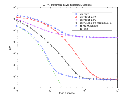
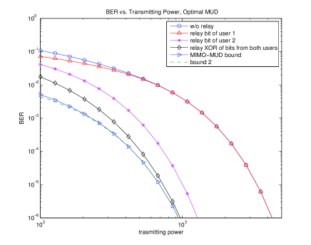
Figure 4(a) and Figure 4(b) show the average BER at the base station as a function of the transmitted power of the users and of the relay for successive cancellation and optimal MUD, respectively. The relay’s location is fixed at position . We can clearly see the higher diversity order of BER vs. power for the proposed protocols. When the transmitted power is sufficiently high, the limiting factor of successive cancellation’s performance is the interference. And that is why we see the curve flattens when the transmitted power grows. We also note the large difference in performance between the case with the relay and the case without. Another interesting observation is that, for successive cancellation in a certain transmitted power range, relaying the first user’s symbol is better, while in another transmitted power range, relaying the second user’s symbol is better. For optimal MUD, to relay the symbol of user is always the best choice. Relaying the XOR of both users’ symbols is always the best protocol, but this requires the use of MUD at the relays. We also show the MIMO-MUD performance bound and bound which assumes perfect channels from source to relay. The two bounds are similar except when successive cancellation hits an error floor. The bounds for optimal MUD are tighter especially when the BER is sufficiently low. When , for optimal MUD , the performance gap between the bounds and the protocol in which the relay XORs bits from both users is dB. When , the gap is dB.
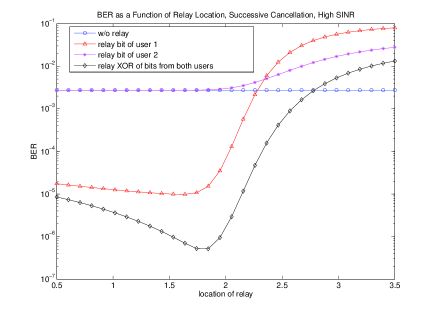
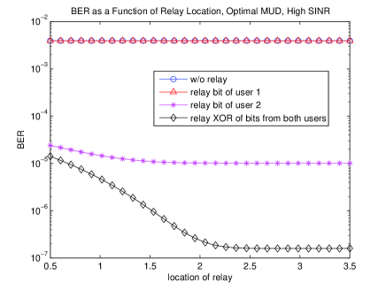
Figure 5(a) and Figure 5(b) show the average BER at the base station as a function of the relay location. There are two users, and both users and the relay use high transmitted power of dB for successive cancellation and dB for optimal MUD. The curves correspond to the case without the relay, with the relay re-transmitting user 1’s (located at position ) symbol, with relay re-transmitting user 2’s (located at position ) symbol, and with the relay re-transmitting the XOR of both users’ symbols (network coding), respectively.
The first observation is that the location of the relay plays a vital role in the system performance, especially for the successive cancellation detector. For successive cancellation, the system with a relay performs better than the system without a relay, only if the relay’s distance from the base station is below position using network coding and below position when the relay helps user 1. If the successive cancellation detector is used, the system performs better without a relay if the relay is too close to the user group. This is because, for successive cancellation, the performance is better if the users have different received power levels. A relay that is too close to the user group will increase the error rate of the successive cancellation detector because of its interference. On the other hand, for optimal MUD, the performance is always better with a relay, especially when the relay is close to the users. However, the performance improvement has a floor. The second observation is that there is a “sweet spot” for successive cancellation eith the location of the relay around position 1.8. This is because the relay’s decoding performance drops if it is located too far away from the sources. The third observation is that the network coding protocol with the relay re-transmitting the XOR of both users’ symbols always performs better than that when the relay just re-transmits one user’s symbol.
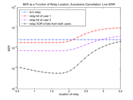
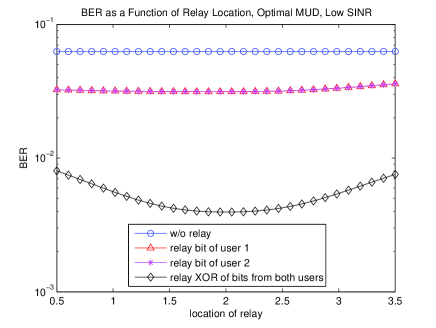
Figure 6(a) and Figure 6(b) correspond to similar setups except the transmitted power is low here (dB for successive cancellation and dB for optimal MUD). For successive cancellation, we observe performance behavior similar to the high transmitted power case, except that the relay can still help when its location is close to the users. The “sweet spot” remains essentially at the same place. For optimal MUD, there exists a “sweet spot” as well at the position around . From the network designer’s point of view, if a fixed relay can be added to the network to improve the performance, the above observations on the relay locations can provide guidance on where to place such a fixed relay.
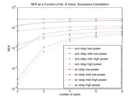
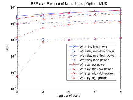
Figure 7(a) and Figure 7(b) show the average BER as a function of the number of users. Here we explore the cases with two to six users. In each case, the users are uniformly distributed in the range . The relay is located at , and transmits the XOR of the nearest two users’ symbols. For successive cancellation, the power settings are dB, dB, dB, and dB for the lower, mid-low, mid-high, and high power setups. For optimal MUD, the power settings are dB, dB, dB, and dB instead. As expected, the performance is best when there are only two users. The performance for the case with more users can be improved by introducing more relays or having the relay transmitting XOR of more users’ symbols.

Finally, we study the problem of whose information should be coded with network coding. Figure 8 shows the average BER as a function of the number of users for the relay to be coded with network coding with different average SNR and different MUDs. We can observe that, in this case, coding more users can improve the system performance. From the above observations, we can see that the system performance degrades as the number of users in the network increases, while the proposed approach with network coding and cooperative MUD can significantly improve the performance by encoding more users.
VI Conclusions
In this paper, based on the fact that the enhancement of some users’ transmissions by cooperative transmission can improve the other users’ performance in certain types of multiuser detectors, we have proposed two new cooperative transmission protocols that utilize MUD as well as network coding. Unlike traditional MUD in which the links are determined by the users’ locations and channels, the proposed cooperative transmission protocols improve the link qualities so that the multiuser detectors can work in their most efficient regions. Moreover, deploying MUD at the relay provides an opportunity to use network coding, which can provide additional coding gain and achieve full diversity. From our analytical and simulation results, it is seen that the proposed protocols achieve much lower average BER, higher diversity order and coding gain, and better asymptotic efficiency, compared to cooperative transmission in networks using single user detection and traditional MUD. The performance gap between the proposed approach and the MIMO-MUD bound is less than dB when the BER is and 1.04dB when the BER is .
Acknowledgment
The authors would like to thank Dr. Huaiyu Dai of North Carolina State University, Dr. Husheng Li of the University of Tennessee, and anonymous reviewers for their constructive discussions and suggestions.
References
- [1] A. Sendonaris, E. Erkip, and B. Aazhang, “User cooperation diversity, Part I: System description,” IEEE Transactions on Communications, vol. 51, no. 11, pp. 1927-1938, November 2003.
- [2] J. N. Laneman, D. N. C. Tse, and G. W. Wornell, “Cooperative diversity in wireless networks: efficient protocols and outage behavior,” IEEE Transactions on Information Theory, vol. 50, no. 12, pp. 3062-3080, December 2004.
- [3] A. K. Sadek, Z. Han, and K. J. Ray Liu, “Distributed relay assignment algorithm for cooperative communications in wireless networks,” in Proc. IEEE International Conference on Communications, Istanbul, Turkey, June 2006.
- [4] J. Luo, R. S. Blum, L. J. Greenstein, L. J. Cimini, and A. M. Haimovich, “New approaches for cooperative use of multiple antennas in ad hoc wireless networks,” in Proc. IEEE Vehicular Technology Conference, vol.4, pp.2769- 2773, Los Angeles, CA, September 2004.
- [5] T. Himsoon, W. Siriwongpairat, Z. Han, and K. J. Ray Liu, “Lifetime maximization with cooperative diversity in wireless sensor networks,” in Proc. IEEE Wireless Communications and Networking Conference, Las Vegas, NV, April 2006.
- [6] Z. Yang, J. Liu, and A. Host-Madsen, “Cooperative routing and power allocation in ad-hoc networks,” in Proc. IEEE Global Telecommunications Conference, Dallas, TX, November 2005.
- [7] Z. Han, T. Himsoon, W. Siriwongpairat, and K. J. Ray Liu, “Energy efficient cooperative transmission over multiuser OFDM networks: who helps whom and how to cooperate,” in Proc. IEEE Wireless Communications and Networking Conference, vol. 2, pp.1030-1035, New Orleans, March 2005.
- [8] W. Siriwongpairat, W. Su, Z. Han, and K. J. R. Liu, “Enhancement for multiband UWB systems using cooperative communications,” in Proc. IEEE Wireless Communications and Networking Conference, Las Vegas, NV, April 2006.
- [9] S. Verdú, Multiuser Detection, Cambridge University Press, Cambridge, UK, 1998.
- [10] L. Venturino, X. Wang and M. Lops, “Multiuser detection for cooperative networks and performance analysis,” IEEE Transactions on Signal Processing, vol. 54, no. 9, pp. 3315-3329, September 2006.
- [11] H. Dai, A. F. Molisch, and H. V. Poor, “Downlink capacity of interference-limited MIMO systems with joint detection,” IEEE Transactions on Wireless Communications, vol. 3, no. 2, pp. 442-453, March 2004.
- [12] R. Ahlswede, N. Cai, S.-Y. R. Li, and R. W. Yeung, “Network information flow,” IEEE Transactions on Information Theory, vol. 46, no. 4, pp. 1204-1216, April 2000.
- [13] Y. Chen, S. Kishore, and J. Li, “Wireless diversity through network coding,” in Proc. IEEE Wireless Communications and Networking Conference, Las Vegas, NV, April 2006.
- [14] Y. Wu, P. A. Chou and S. -Y. Kung, “Information exchange in wireless networks with network coding and physical-layer broadcast,” in Proc. 39th Annal Conference on Information Sciences and Systems, The Johns Hopkins University, Baltimore, MD, March 2005.
- [15] J. N. Laneman, “Network coding gain of cooperative diversity,” in Proc. IEEE 2004 Military Communications Conference, Monterey, CA, October 2004.
- [16] Y. Cao and B. Vojcic, “MMSE multiuser detection for cooperative diversity CDMA systems,” in Proc. IEEE Wireless Communications and Networking Conference, Atlanta, GA, March 2004.
- [17] D. N. C. Tse and S. V. Hanly, “Linear multiuser receivers: Effective interference, effective bandwidth and user capacity,” IEEE Transactions on Information Theory, vol. 45, no. 2, p.p. 641-657, March 1999.
- [18] T. Tanaka, “A statistical-mechanics approach to large-system analysis of CDMA multiuser detectors,” IEEE Transactions on Information Theory, vol. 48, no. 11, p.p. 2888-2910, November 2002.
- [19] D. Guo and S. Verdú, “Randomly spread CDMA: Asymptotics via statistical physics,” IEEE Transactions on Information Theory, vol. 51, no. 6, p.p. 1983-2010, June 2005.
- [20] S. Chung and A. Goldsmith “Degrees of freedom in adaptive modulation: A unified view”, IEEE Transactions on Communications, vol. 49, no. 9, pp. 1561-1571, September 2001.