Dynamical Coupling Between Ferromagnets Due to Spin Transfer Torque
Abstract
We use a combination of analytic calculations and numerical simulations to demonstrate that electrical current flowing through a magnetic bilayer induces dynamical coupling between the layers. The coupling originates from the dependence of the spin transfer torque exerted on the layers on the relative orientations of their magnetic moments. We demonstrate that such coupling modifies the behaviors of both layers, significantly affecting the the stability of the current-induced dynamical regimes and the efficiency of current-induced magnetic reversal.
pacs:
85.75.-d, 75.60.Jk, 75.70.CnCurrent-induced spin transfer (ST) effect cornellorig is the most promising mechanism for manipulation of magnetic nanodevices, due to the simplicity of the implementation and potential power benefits. The main obstacle for viable applications of the effect is the large magnitude of the required current, which is too close to the limit of the physical stability of devices. A basic magnetoelectronic device consists of a magnetic bilayer F1/N/F2, where F1 is a magnet needed to polarize the current, N is a metallic or insulating nonmagnetic spacer, and F2 is a nanomagnet whose magnetic configuration can be changed by current via ST. The efficiency of spin transfer can be characterized by the zero-temperature threshold current for the onset of current-induced magnetic dynamics of F2. In the framework of the widely accepted spin transfer torque (STT) model slonczewski ; fert ,
| (1) |
where is the electron charge, is the effective magnetic field which includes the magnetic anisotropy of F2, is the Gilbert damping parameter, and is a function of the relative orientations of the magnetic moments and of F1 and F2, respectively, which depends predominantly on the spin polarizing properties of F1.
Several directions are pursued for reducing . The function is proportional to the polarization of the current generated by F1 iswvsmr . Here, and are the spin-up and spin-down contributions to the current. Therefore, can be reduced by enhancing the spin-polarizing properties of F1. However, the difference between the typical value for the common F1 such as Py=Ni80Fe20 and the largest possible is small, limiting the room for improvement. Alternatively, can be reduced by decreasing , which at small external field is dominated by the anisotropy of F2. Simply reducing the magnetization of F2 would decrease , but this would also compromise the stability of the magnetic configuration. Devices with perpendicular magnetic anisotropy can in principle overcome this limitation, but the potential advantages were offset by the reduced polarization and increased fullerton . Attempts to reduce while stabilizing F2 with an antiferromagnet have encountered similar complications ebst .
Here, we discuss the previously unexplored mechanism affecting the efficiency of ST, involving simultaneous current-induced effects on both ferromagnets in a bilayer consisting of F1 and F2. This mechanism couples the dynamics of the two magnets. We describe analytic results for a simple model system, and present realistic numerical calculations in macrospin approximation. Our results demonstrate that can be either increased or reduced with respect to the value given in Eq. 1 by a suitable choice of F1 and F2. Most importantly, we show that the dynamics of both magnets are always excited simultaneously, and thus both magnetic layers always participate in the current-induced behaviors.
Analytic Model. To introduce the idea of dynamical coupling of magnetic layers by STT and understand the consequences of such coupling, we consider an idealized system of two nanoscale magnets F1 and F2 represented by the magnetic moments and , whose magnitudes are fixed in the macrospin approximation. For simplicity, this model neglects the demagnetizing fields of the ferromagnets and their dipolar coupling. The dynamics of the magnetic moments in the presence of current flowing from F1 to F2 can be described by two Landau-Lifshitz equations coupled by the STT term slonczewski
| (2) |
where is the gyromagnetic ratio, and are the spins of F1,F2. For simplicity, we assume the same for both magnets, and neglect the dependence of on the relative orientations of and . The experimentally determined values of are similar in both parallel (P) and antiparallel (AP) configurations of the magnetic moments, justifying the latter approximation iswvsmr . In the limit , the last term in Eq. 2 for is negligible due to the large value of , resulting in a static solution for . The equation for then yields precession of at determined by Eq. 1, consistent with the models for the dynamics of a single ferromagnet. At , the AP state becomes stable, and the solution for is a precessional reversal into this state.
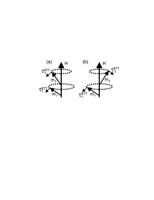
We are interested in the solution of Eq. 2 for comparable values of and . As illustrated in Fig. 1, STT exerted on both layers can induce their simultaneous precession around the magnetic field with cone angles and . A simple estimate shows that a stable configuration involves precession of and with the same polar angle (Fig. 1(a)). To demonstrate the stability of this configuration, we assume that lags behind by a small polar angle . The torque exerted on then acquires an additional component in the polar direction, resulting in the increase of its angular frequency by . Similarly, a component of STT exerted on in the polar direction increases its angular frequency by . The stability of the coupled precession with respect to fluctuations of requires that , which is satisfied if . The derivation given below shows that the latter inequality usually holds, ensuring the stability of in-phase precession.
The stationary form of Eq. 2 for in-phase precession is
| (3) |
The filtering properties of F1 and F2 are often similar, resulting in . Eqs. Dynamical Coupling Between Ferromagnets Due to Spin Transfer Torque then lead to
| (4) |
which satisfies the condition for the stability of in-phase precession, as discussed above. Eqs. Dynamical Coupling Between Ferromagnets Due to Spin Transfer Torque yield the current for the precession onset . We emphasize three main consequences of Eqs. Dynamical Coupling Between Ferromagnets Due to Spin Transfer Torque. Firstly, both moments always precess simultaneously. Secondly, the relation between the amplitudes of the dynamics of the two moments is determined by the ratio . In particular, the dynamics of is negligible at . Precession of can then occur only at . Conversely, the dynamics of is negligible at , while precession of can occur at . Finally, also depends on . In particular, it diverges when the magnetic moments become equal (A=1).
To determine the nature of excitations and stability regimes for the magnets coupled by STT, we insert Eq. 4 into the second of Eqs. Dynamical Coupling Between Ferromagnets Due to Spin Transfer Torque, leading to
| (5) |
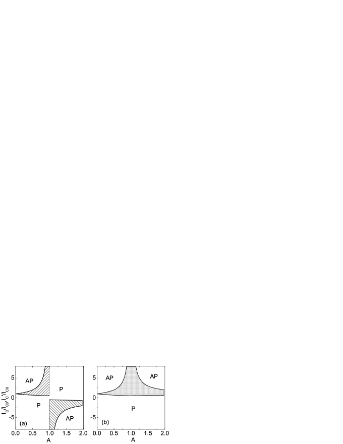
where . Eq. 5 describes a monotonically decreasing function of , which implies that precession is unstable at any . On the other hand, both and are stable in the range , where is the current at which the AP state becomes stable. The resulting stability diagram is shown in Fig. 2(a), where the bistable regions are hatched.
As a consequence of the dynamical coupling due to STT, the value of is reduced by a factor of two at , while diverges. It remains to be seen whether these coupling effects can be utilized to increase the efficiency of magnetoelectronic devices. Current-induced bistability in devices with should generally result in telegraph-type noise due to thermally activated transitions between the two stable configurations. Such noise is detrimental to most applications. However, such configuration may be useful if small-amplitude current-induced dynamics is undesired. For , dynamical coupling also makes it impossible to induce dynamical states at . Similarly, dynamics cannot be induced at for . We shall see below that this result also holds for a more realistic model. The fact that bipolar current-induced excitations were observed cornellbipolar ; kentbipolar must indicate a significant breakdown of the macrospin approximation in these experiments.
Applications of magnetoelectronic devices in microwave generation require to be minimized, and stable precession to be achieved over a significant range of . We demonstrate below that can be reduced by the current-induced coupling when and have opposite signs. This requires reversing the spin anisotropy of one of the ferromagnets, which can be accomplished by doping F1 or F2 with impurities providing appropriate spin-dependent scattering in their bulk, and/or by choosing N that inverts the spin anisotropy of electron scattering at F/N interface inverted . For simplicity, we now assume that . The torques exerted on the two magnets now result in the mutual attraction of the moments at , resulting in a stable collinear configuration at for any . Dynamical states are induced only by , regardless of the value of . Fig. 1(b) shows that the relative precession phases of and are now shifted by . Estimates similar to the ones presented above for show that this precessional configuration is stable.
Eq. 4 for the precession cone angles of the two moments still holds, but Eq. 5 is replaced with
| (6) |
The resulting stability diagram shown in Fig. 2(b) includes a region of stable coupled precession of the two magnets. At , the precession onset current is reduced by a factor of two, while the largest value of at which the precession remains stable diverges.
Numerical Simulations. To determine whether the current-induced coupling remains robust in realistic systems, we solved Eqs. 2 numerically. We used the geometry and the magnetic properties typical for the spin-transfer devices, in which F1 and F2 are Py layers with emu/cm3 and thicknesses and , patterned into an elliptical shape with dimensions nm cornellorig . We used the material parameters known from the magnetotransport measurements bassgmr . The demagnetizing fields were taken into account. The dipolar coupling was neglected to eliminate its influence on the interpretation of current-induced behaviors. We included the dependencies of the spin transfer efficiencies on the configuration of the magnetic system to take into account the slight experimental asymmetry between the PAP and APP reversals iswvsmr . The equations were numerically integrated by the stochastic Heun method with a fixed time step set to psec. To verify the convergence, the step size was decreased by a factor of two, which did not significantly affect the results. Random field approximation was used to model the thermal activation between different current-induced modes, with temperature set to K. Damping parameter was used for both magnets cornellscience .
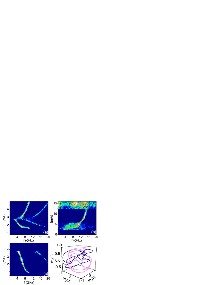
The model was tested for three limiting cases: , , and . In the first case, STT induced the dynamics of only , and only at . Fig. 3(a) shows the normalized spectra of the component of along the hard in-plane axis for . The peaks correspond to several harmonics of the precession frequency. After the onset of small-angle precession at mA, the frequency of precession decreases due to transition to large-angle clamshell precession trajectory. The transition to the out-of-plane precession at mA results in the increase of precession frequency. These results are consistent with the published calculations for single layer dynamics, and are in overall agreement with the experiments kiselevnature . Similar spectra were obtained for the dynamics of at , for . Calculations for yielded identical spectra for and regardless of the sign of , as expected for this symmetric geometry. Additionally, the calculations for and reproduced the sequential thermally activated flipping of and experimentally observed in symmetric magnetic nanopillars wenglee .
Current-induced coupling of the dynamics of two layers significantly affected the spectra at , as illustrated in Fig. 3(b) for . The onset current for the magnetic dynamics is larger than in Fig. 3(a), in agreement with the results of the analytic model presented above. At mA mA, the data exhibit a broad incoherent excitation spectrum due to random transitions between different types of precession dynamics of . Specifically, the precession of alternates between the clamshell-type and the out-of-plane trajectories, depending on the relative phase with the elliptical precession of . The latter is not phase-coherent with . The formation of a sharp peak at mA mA is associated with the complete transition to out-of plane precession of , resulting in nearly static deflection of towards . At mA, the oscillations of become sufficiently large to disrupt the periodic precession of , resulting in increasingly chaotic dynamics of both. Fig. 3(b) shows the trajectories of and over a 0.5 nsec period at mA. Despite nearly chaotic behavior of both moments, some parts of the trajectory of resemble clamshell and out-of-plane precession. The chaotic behaviors persisted in deterministic simulations at , eliminating thermal fluctuations as their cause. Based on the analysis of the trajectories, we believe that these behaviors are caused by a combination of large phase space associated with the dynamics of both magnets, and nonlinear nature of the large-amplitude magnetic dynamics.
At , the broad excitation band at small and the out-of-plane precession peak gradually disappeared. At , only the mA continuum remained, and similar features appeared at mA. There were no excitations at for all , in agreement with the analytic results described above. These results seem to be inconsistent with the intuitive picture, according to which can induce the dynamics of , while can induce the dynamics of even for tsoisymmetric . However, analysis of the magnetic trajectories shows that all oscillations of at are efficiently suppressed by closely following , thus reducing STT exerted on both layers.
Calculations for showed that is reduced in this case, in agreement with the analytic model. Fig. 3(c) shows spectra calculated for . mA is slightly over half of the value obtained for . Therefore, reduction of the critical current for appears to be a robust feature of dynamical coupling. The spectra do not exhibit broadening and chaotic dynamics characteristic of the data. The peaks in Fig. 3(c) abruptly terminate at mA due to the formation of a static stable configuration with and oriented opposite to each other perpendicular to the film plane. Such static configuration is, however, not present for .
We have performed additional calculations without some of the simplifying assumptions of our model. In particular, we tested the effects of different magnetic damping in the two magnets and different magnetizations. We also checked the effect of the dipolar coupling between the layers. The modifications did not qualitatively change our conclusions regarding the effects of current-induced coupling, as long as the resonant frequencies of the two layers remained similar to each other.
In summary, we have analyzed the simultaneous effects of spin torque on both layers in a magnetic bilayer. We showed that the spin torque results in dynamical coupling between the layers, modifying their individual current-induced dynamical properties. In particular, the onset of magnetic precession of both magnetic always occurs at the same current. In case of similar spin-transport anisotropy of both layers, the onset current for magnetic precession is increased, diverging for identical values of the moments of the two layers. Realistic numerical simulations show that coupling often leads to incoherent dynamical regimes associated with transitions between different dynamical states of the bilayer. However, for the opposite spin-transport anisotropy of the two layers, the onset current for the magnetic precession is decreased, and coherence is maintained even for the identical dimensions of the magnetic layers. This effect of dynamical coupling on the spin transfer efficiency can become useful for implementing devices with improved performance.
This work was supported by the NSF Grant DMR-0747609. I thank Lidia Novozhilova for help with numerical simulations.
References
- (1) J.A. Katine, F.J. Albert, R.A. Buhrman, E.B. Myers, and D.C. Ralph, Phys. Rev. Lett. 84, 3149 (2000).
- (2) J. Slonczewski, J. Magn. Magn. Mater. 159, L1 (1996).
- (3) A. Fert, V. Cros, J.-M. George, J. Grollier, H. Jaffres, A. Hamzic, A. Vaures, G. Faini, J. Ben Youssef, H. Le Gall, J. Magn. Magn. Mater. 272-276, 1706 (2004).
- (4) S. Urazhdin, N.O. Birge, W.P. Pratt Jr., J. Bass, Appl. Phys. Lett. 84, 1516 (2004)
- (5) S. Mangin, D. Ravelosna, J.A. KAtine, M.J. Carey, B.D. Terris, and E.E. Fullerton, Nature 5, 210 (2006).
- (6) S. Urazhdin and N. Anthony Phys. Rev. Lett. 99, 46602 (2007).
- (7) M. Tsoi, J.Z. Sun, and S.S.P. Parkin, Phys. Rev. Lett. 93, 036602 (2004).
- (8) S.I. Kiselev, J.C. Sankey, I.N. Krivorotov, N.C. Emley, A.G.F. Garcia, R.A. Buhrman, and D.C. Ralph, Phys.Rev. B 72, 064430 (2005).
- (9) B. Ozyilmaz, A.D. Kent, M.J. Rooks, and J.Z. Sun, Phys. Rev. B 71, 140403 (2005).
- (10) M. AlHajDarwish, H. Kurt, S. Urazhdin, A. Fert, R. Loloee, W. P. Pratt, Jr., and J. Bass Phys. Rev. Lett 93, 157203 (2004).
- (11) Bass and W. P. Pratt, Jr., J. Magn. Magn. Mat. 200, 274 (1999); W. P. Pratt, Jr. et al., IEEE Trans. Magn. 33, 3505 (1997).
- (12) I.N. Krivorotov, N.C. Emley, J.C. Sankey, S.I. Kiselev, D.C. Ralph, R.A. Buhrman, Science 307, 228 (2005).
- (13) S.I. Kiselev, J.C. Sankey, I.N. Krivorotov, N.C. Emley, R.J. Schoelkopf, R.A. Buhrman, D.C. Ralph, Nature 425, 380 (2003).
- (14) W. Lim, N. Anthony, A. Higgins, S. Urazhdin, arXiv:0801.1807v1.
- (15) M. Tsoi, J.Z. Sun, and S.S.P. Parkin, Phys. Rev. Lett. 93, 036602 (2004).