Cross-talk suppressed multi-anode MCP-PMT
Abstract
We have developed a 4-channel multi-anode MCP-PMT, SL10, which exhibits a performance of ps for single photons with and under a magnetic field of B . The cross-talk among anodes has been extensively studied. We have taken two measures to suppress it: one is to configure the SL10 to an effectively independent 4 small pieces of MCP-PMT’s by segmenting an electrode of the second MCP-layer; the other is to use a constant fractional discriminator. Remarkable improvement has been achieved.
keywords:
MCP-PMT , cross-talk , TOP counter, , , , , , , , , , , , , , ,
1 Introduction
A micro-channel plate (MCP) photo-multiplier tube (PMT) provides a good time response. Our R&D work had obtained a transit time spread (TTS) of ps for single photons with a channel-hole size of 10 mϕ without a magnetic field (B) or with B1.5 T strength [1]. Such an MCP-PMT made it possible to realize ps of a TOF counter for 4 GeV/c pion beams [2]. Furthermore, an MCP-PMT with a multi-alkali photocathode maintains its timing performance up to an integrated irradiation of photons/cm2 or an integrated output charge amount of C/cm2 under an irradiation rate of photons/cm2/s [3]. The MCP-PMT having these superb properties lets us develop a new type of Cherenkov ring imaging counter, a time-of-propagation (TOP) counter [4], for particle identification at a planned Super-KEKB factory with an expected luminosity of /cmsec, which is 50-times as intense as the achieved luminosity of the current KEKB factory, and is expected to survive for more than 14 years under this situation.
We here report on R&D results of a newly developed MCP-PMT, which is equipped with 4 anodes rather than a single anode, and shaped to be square, not round, from the required performance on the TOP counter. When setting a multi-anode structure, an additional R&D issue arises: it shows a cross-talk effect. While cross-talk basically occurs among the anodes, its influence is in most cases is harmless for measurements of the incident-particle energies or a number of tracks in terms of the pulse-height of output signals. However, for a precise time measurement, as discussed here, the cross-talk deteriorates the timing performance, and sometimes makes it ineffectual, in much the same way that occurs for a vacuum PMT, as reported [5]. Based on our tests for various modified versions of the MCP-PMT, we take a specific measure to reduce the cross-talk while keeping its time resolution, as reported below. (We hereafter abbreviate MCP-PMT as simply PMT.)
2 Multi-anode MCP-PMT: SL10
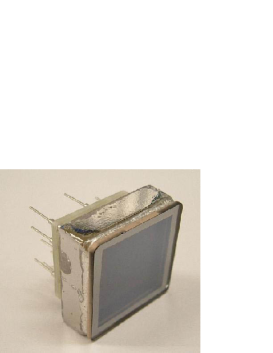
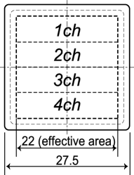
We manufactured two versions of 4-channel linear-array multi-anode MCP-PMT’s, and named them SL10, as can be seen in Fig. 1. The difference in the versions only concerns the electrode of the second MCP-layer, facing to the anodes: SL10-s has a uniform electrode over the whole MCP surface, while SL10-m has an electrode subdivided into 4 segments facing the individual 4 anodes.
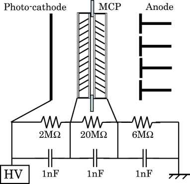
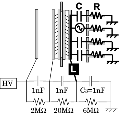
A schematic of the internal structure and high-voltage (HV) supply network of SL10-s is drawn in Fig. 2. Both versions of SL10’s have the same characteristics, as listed in Table 1. They are two-stage MCP’s with a multi-alkali photocathode; the channel-hole size and the thickness of an MCP-layer are 10 m and 400 m, respectively. The anode plane has a size of 2222 mm2, between which there is a gap of 0.3 mm.
| PMT size | 27.5 27.5 15.6 mm3 |
|---|---|
| Effective area | 22 22 mm2 |
| Photocathode | Multi-alkali |
| Number of MCP layers | 2 |
| MCP channel diameter | 10 m |
| MCP aperture | 60 % |
| MCP bias anngle | 13∘ |
| PhotocathodeMCP gap | 2 mm |
| MCPMCP gap | 0.03 mm |
| MCPAnode gap | 1 mm |
| Al protection layer | No |
| Anode | 4 1 linear array |
| Anode width | 5.3 mm |
| Anode gap | 0.3 mm |
| Supplied maximum HV | 3.5 kV |
| Quantum efficiency | 20 % at 350 nm |
| Correction efficiency | % |
| Gain | at 3.5 kV |
| Transit time spread | 29 ps at 3.5 kV |
| Dark count | kHz/ch |
3 Performance of SL10
The performance of SL10, square-shaped and a multi-anode PMT, is measured for single photons, and compared with those of a similar type of MCP-PMT’s, but with a round-shaped and a single anode (Hamamatsu Photonics K.K. (HPK), R3809U-50-11X and -25X, referred to as HPK6 (the channel-hole diameter of 6 m) and HPK10 (10 m) in [1], respectively).
3.1 Set-up
A pico-sec light pulser (HPK, PLP-02-SLDH-041) is used to generate light of wavelength nm with a pulse width of ps at a repetition rate of 1 kHz. Its intensity is attenuated down to a single-photon level by diffusers and filters, and is then led to the SL10 surface by an optical fiber. This system is set inside a magnet in the case of a measurement of the SL10 response based on the B field strength, where the SL10 axis is placed so as to be parallel along the B field.
The waveform of the output signals of the anode is recorded by a digital oscilloscope (Hewlett Packard, Infinium). To measure the charge and timing of the output pulse from individual anodes, it is fed into an attenuator (Agilent, 8495B: attenuation = 0 - 70 dB, frequency 18 GHz) and then to an amplifier (HPK, C5594: gain= 36 dB, frequency = 50 kHz - 1.5 GHz). One of the amplifier outputs is fed into a CAMAC ADC (0.25 pC/count) module, and the other output is sent into a CAMAC TDC (25 ps/count) module through a discriminator (Phillips Scientific, model-708) with a threshold voltage of 20 mV. It is 1/7 of the pulse height.
A drawing of a similar setup is shown in Fig. 1 in [1].
3.2 Performance for single-photon detection
Data presented in this subsection were obtained for the SL10-s, but there is no essential difference from that of the SL10-m.
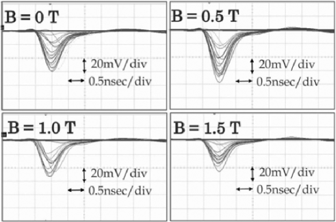
3.2.1 Raw signal and B field
Figures 3 show the output signals for single photons under various B strengths. The pulse height is 30 mV and the rise time is 500 ps at HV = 3.5 kV. These properties are consistent with those observed by the round-shaped PMT with a single anode, particularly HPK6 (see [1]).
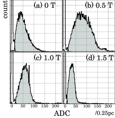
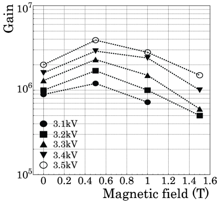
3.2.2 Multiplication gain vs. B field
Figure 4 shows the charge distributions of the output pulses under various B fields. A single photon peak is clearly seen around the 45-th, 70-th, 60-th and 40-th channel at B=0, 0.5, 1.0 and 1.5 T, respectively. From these output charges for single photons, the typical multiplication gain was evaluated, as indicated in Fig. 5, with several different HV’s from 3.1 kV to 3.5 kV with a 0.1 kV step: The maximum of was attained at B = 0.5 T. The behavior of vs B is quite similar to that of HPK10, but its absolute magnitude is 5-10 times larger than that of HPK10. This difference is inferred to be due to a variation of individual MCP manufacturing batches.
3.2.3 vs. photon rate
A huge rate of medium/high energy photons could be produced regarding the beams of the Super-KEKB accelerator; their pair creation of the TOP quartz radiator then yielded many Cherenkov photons as backgrounds. At our TOP-counter configuration [6], the photon background rate at the Super-KEKB was estimated to be /cm2/s on the PMT surface [3], by linearly extrapolating from the single rate of the present Belle TOF counter. The irradiation of a PMT by such a high-rate of photons could cause a drop due to a finite recovery time of the effective HV field inside the channel-hole, apart from a shortening of the PMT lifetime.
The photon rate on the SL10 was varied by changing the light-pulser frequency from 1 kHz up to 1 MHz, and the light intensity from 1 up to 600 photons/pulse. The resulting variation is shown in Fig. 6 as a function of the photon rate. The SL10 stably functions up to a photon rate of /cm2/s without significantly deteriorating its . This rate corresponds to about 100-times higher than the expected rate at the Super-KEKB factory.

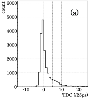
3.2.4 TTS vs. B field
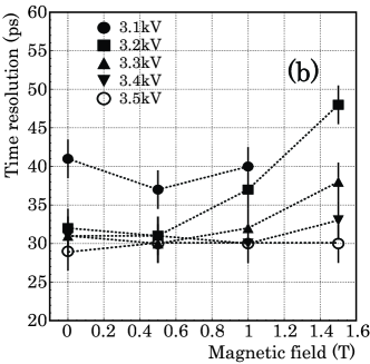
The time-walk corrected time response for single photons is plotted in Fig. 7(a). The dominant peak ( TDC ) yields the time resolution of ps. The tail component is supposed to be due to the delayed photoelectrons bouncing from the surface of the first MCP layer. Fig. 7(b) shows the relation of vs. B; ps can be attained in the case of . This performance is similar to those of both HPK6 and HPK10 (see Fig. 7 in [1]).
4 Cross-talk and Its measure
The cross-talk among the anodes is a general issue for multi-anode detectors; moreover, it is substantial for a precise time measurement of the single photons, as reported in [5]. In the case of the TOP-counter, 20 Cherenkov photons could be detected by 15 pieces of the SL10’s, each of which is equipped with 4 anodes, on a side edge of the quartz-bar, when a charged track passes through the bar. There are then appreciable probabilities that plural SL10’s detect photons in an event. A primary single-photon would induce cross-talk on other anodes in the same SL10, so that the pulse shape of the secondary arriving single-photon on the anode would be affected, and thus deteriorate the timing information.
We studied and then reduced the influence of the cross-talk by modifying the electrode structure as in the case of the SL10-s to SL10-m.
No B-field is applied in the following studies.
4.1 Phenomena
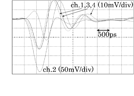
Fig. 8 shows the anode signals from the SL10-s in the case that an anode, channel 2, is irradiated by a sufficient number of photons, 20, through a spot of 1 mmϕ, to observe the cross-talk signals at any other channel. The cross-talk pulses show a differential shape of the signal pulse, and its relative pulse height to the signal is 1/5 1/3, and does not depend on the distance among anodes that measure the signals and cross-talks. As is can be seen in Fig. 3, the signal pulse height of single photons is mV, so that the induced cross-talk height for single photons is below the threshold voltage of 20 mV. However, as demonstrated later in Fig. 11, the base-line fluctuation caused by the cross-talk would make the time measurement ineffectual for a consecutive photon on a channel other than ch.2.
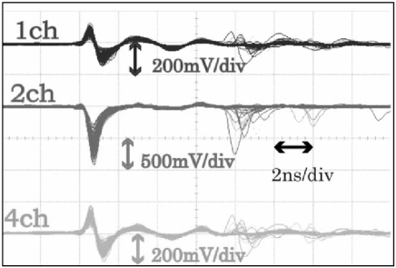
Second signals can be seen at ns after the primary signals in Fig. 8. It is caused by feedback ions, yielded in the multiplication process of the micro-channel plate; the second pulses also induce cross-talk at other anodes.
4.2 Origin
We extensively studied the cross-talk on a multi-anode 16-channel linear array vacuum PMT [5], and here just also found the same phenomena for the SL10.
The cross-talk in this case might be induced through, especially, the last electrode, facing the anodes, of the second MCP-layer. An internal structure of SL10-s, and its readout and HV circuits are illustrated in Fig. 9. The anode, mm2, and the last electrode of the MCP separated by a 1 mm gap, would form a capacitance of 1 pF; a short HV line from the HV bleeder network to the last electrode would yield an inductance of 50 nH; also, individual anodes are terminated with a resistance of .
4.3 Measure
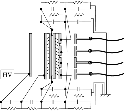
We thought out that one way to reduce the cross-talk by disconnecting this RLC loop circuit is to make a segmentation of the MCP electrode facing to 4 anodes, and to prepare 4 separate HV networks, as illustrated in Fig. 10. Since the MCP is a high-resistance material, 20 M per plate, the impedances between the segmented electrodes are quite large, electrically well disconnected.
4.4 Performance of the segmented SL10, SL10-m
4.4.1 Signals
Anode signals of the SL10-m can be seen in Fig. 11, where the setup condition is the same in the case of Fig. 8, except that the number of photons irradiated is 10, rather than 20. The pulse-height ratio between the cross-talk and the signal is now 10. It has been improved by a factor of 2, compared to that of SL10-s.
4.4.2 under cross-talk
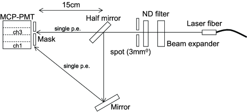
We prepared the setup shown in Fig. 12 to measure the time resolution in a case that two photons hit different anodes of the SL10-s and SL10-m within an adjacent narrow time period, supposing Cherenkov ring imaging photons in the TOP-counter. The light beams from the pulser are divided into two by a half mirror. The primary light is detected by ch.3 through a mask, and the divided and then delayed light is by ch.1 as shown in Fig. 12. The delay time, , is adjusted to be within a range of up to 3 ns, by changing the distance of the second mirror to the SL10. A light pulse is attenuated down to single-photon level by beam expanders and filters, upstream of the half mirror.
The observed time resolution, , for the delayed photons is plotted in Fig. 13 as a function of by open circles for SL10-s and open squares for SL10-m, using a discriminator of the voltage threshold type (Phillips Scientific, model-708, threshold = 20 mV). For SL10-s, which provides ps in the case of single photons with no cross-talk (see, Fig.7), there is no data point at ns because the discriminator hits the cross-talk pulse before the delayed signal arrives.
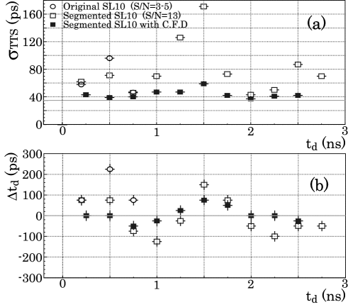
For SL10-m, the cross-talk pulse is sufficiently suppressed so that only the delayed signal is detected by the discriminator at any range. However, strongly depends on . For ns, around which the cross-talk effect from the primary signal is the largest, becomes ps, while in the other region, where the fluctuation of the base line is rather small, ps. Even so, the latter resolution is worse than the ps attained at the incidence of sole single photons.
4.4.3 Further measure with a constant fractional discriminator
Although SL10-m successfully reduces the cross-talk, it does not recover the original time resolution of ps for single photons. The cross-talk effect also appears as a shift of the observed absolute time of the delayed photons, as plotted in Fig. 13(b). The difference, , between the observed time and behaves as expected from the cross-talk pulse (see, Fig. 11). When the base line shifts to the positive side in voltage, moves to a positive delay, and vise-versa. This fact indicates that the signal pulse is not broken away by the cross-talk, rather it keeps its intrinsic signal shape upon a tiny cross-talk disturbance.
We replaced a leading-edge type of discriminator with a constant fractional discriminator (CFD, Kaizu-works KN381), since the latter provides an output pulse at zero-crossing timing of a differentiated input pulse so that it would not be strongly affected by the cross-talk, as the former would be. The resulting and with the cross-talk are plotted by closed squares with error bars in Fig. 13. The time resolution largely improved to ps with no large variation in . The timing shift has also been reduced by a factor of 2: ps. However, because its maximum shift is about the same size as the time resolution it is not a trivial matter, unless it is corrected by referring to the timing of the primary signal.
5 Summary and Discussions
We have developed a square-shaped 4-anode MCP-PMT, SL10, to measure the precise timing of single photons. It provides a performance that satisfies the requirement on our TOP-counter: , ps for single photons under a 1.5 T magnetic field strength, and durable up to /cm2/s of a high photon rate.
In order to suppress the cross-talk effect on the timing measurement in the case of plural photon injection, we have taken two measures. One way is to subdivide the electrode of the last MCP-layer into 4 pieces, facing the anodes: It successfully reduces the cross-talk size to one half. The second way is to use a constant fractional discriminator, instead of the leading-edge type one. The time resolution is largely recovered up to ps, while not yet restoring the original resolution of ps.
Acknowledgments
This work is supported by a Grant-in-Aid for Science Research on Priority Area (Mass Origin and Supersymmetry Physics, 18071003) from the Ministry of Education, Culture, Sports, Science and Technology of Japan, and by a Grant-in-Aid for Creative Scientific Research (18GS0206) from the Japan Society for the Promotion of Science.
References
- [1] M. Akatsu et al., Nucl. Instr. and Meth. A 528 (2004) 763.
- [2] K. Inami et al., Nucl. Instr. and Meth. A 560 (2006) 303.
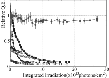
- [3] N. Kishimoto et al., Nucl. Instr. and Meth. A 564 (2006) 204. The MCP-PMT (HPK-w: HPK6 equipped with a feedback protection layer between the photocathode and the first MCP) held a stable quantum efficiency (QE) up to an integrated irradiation of photons/cm2. After the publication, we extended the measurement up to photons/cm2, and no appreciable degradation of QE was still observed, as shown below.