Resonant electron heating and molecular phonon cooling in single C60 junctions
Abstract
We study heating and heat dissipation of a single C60 molecule in the junction of a scanning tunneling microscope (STM) by measuring the electron current required to thermally decompose the fullerene cage. The power for decomposition varies with electron energy and reflects the molecular resonance structure. When the STM tip contacts the fullerene the molecule can sustain much larger currents. Transport simulations explain these effects by molecular heating due to resonant electron-phonon coupling and molecular cooling by vibrational decay into the tip upon contact formation.
The paradigm of molecular electronics is the use of a single molecule as an electronic device Aviram74 . This concept is sustained on the basis that a single molecule (or a molecular thin film) should withstand the flow of electron current densities as large as 1010 A/m2 without degrading. A fraction of these electrons heat the molecular junction through inelastic scattering with the molecule NitzanJPCM07 . The temperature at the junction is a consequence of an equilibrium between heating due to electron flow and heat dissipation out of the junction. The former is dominated by the coupling of electronic molecular states with molecular vibrons NitzanJPCM07 ; NitzanPRB07 ; PecchiaPRB07 . The latter depends on the strength of the vibrational coupling between the “hot” molecular vibrons and the bath degrees of freedom of the ”cold” electrodes.
Theoretical studies predicted that current-induced heating in molecular junctions can be large enough to affect the reliability of molecular devices NitzanJPCM07 . However, experimental access to this information is very limited. Recent studies of the thermally activated force during molecular detachment from a lead HuangNL06 ; HuangNN07 and of structural fluctuation during attachment to it BerndtPRL07 reveal that the temperature of a molecular junction can reach several hundred degrees under normal working conditions, thus revealing that present devices work on the limit of practical operability Tour00 . Heat dissipation away from the junction becomes an important issue.
In this work, we characterize the mechanisms of heating and heat dissipation induced by the flow of current across a single molecule. Our approach is based on detecting the limiting electron current inducing molecular decomposition at varying applied source-drain bias (i.e. the maximum power one molecule can sustain). We use a low temperature scanning tunneling microscope (STM) to control the flow of electrons through a single C60 molecule at an increasing rate until the molecule decomposes. By comparing the power applied for decomposition (P) in tunneling regime and in contact with the STM tip we find that it depends significantly on two factors: i) P decreases when molecular resonances participate in the transport, evidencing that they enhance the heating; ii) P increases as the molecule is contacted to the source and drain electrodes, revealing the heat dissipation by phonon coupling to the leads. A good contact between the single-molecule (SM) device and the leads is hence an important requirement for its operation with large current densities.
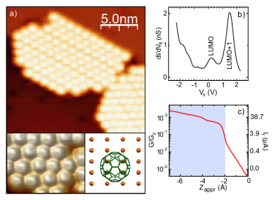
Our experiments are carried out in a custom-made ultra-high vacuum STM at a temperature of 5 K. We choose a Cu(110) single crystal surface because here C60 adsorbs in a well-defined configuration, between 4 of the top most Cu atoms FaselPRB99 . By annealing a sub-monolayer film of C60 to 470 K we produce ordered fullerene islands with a pseudo-hexagonal structure (Fig. 1(a)), in which C60 adsorbs keeping a pentagon-hexagon C-C bond pointing upwards. Scanning tunneling spectroscopy (STS) (Fig. 1(b)) shows a clear spectroscopic fingerprint characterized by a strong resonance at 1.5 eV above the Fermi level, and associated to the alignment of the LUMO+1 resonance (LUMO: lowest unoccupied molecular orbital). The LUMO resonance appears as a weaker broader peak around 0.2 eV and is partially occupied note2 . A spectrum like the one shown in Fig. 1(b) is thus taken here as a litmus test for the integrity of the C60 molecule.
In our experiment, we approach the STM tip notetip a distance Z towards a single C60 at constant sample bias (V) and record the current thus flowing through the molecule (I(Z)). The tunnel regime (identified here as the exponential regime in the I(Z) plots) extends until the junction conductivity reaches 0.03 G0 (G0=77.5 S). Beyond this point, a tip-C60 contact starts to be formed, and the I(Z) plots deviate smoothly from the exponential behavior GimzPRL95 ; BerndtPRL07 . C60 is very stable under the proximity of the STM tip. If a small positive sample bias (V0.6) is used, C60 withstands tip contact and indentations of several Ångstroms, holding currents close to 100A (Fig. 1(c)).
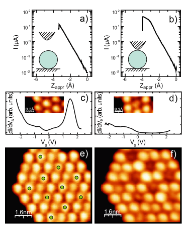
When the value of V is increased above 0.6 V, C60 degrades during the tip approach, as we could identify from three facts (Fig. 2): i) a sharp discontinuity in the I(Z) plots indicates an irreversible change in the molecule; ii) the height of the degraded molecule is typically more than 1 Å lower than its neighbors; iii) the dI/dV spectrum reveals that the characteristic resonance structure vanishes. The precise way in which C60 is degraded can not be determined exactly in our measurements. The disappearance of molecular resonances in the spectra hints that the most probable result is a rupture of the icosahedral carbon cavity. The decomposition is observed solely on the molecule selected for the indentation. Thus, we can discard that an electron-induced polymerization with neighboring molecules takes place ZhaoAPL94 .
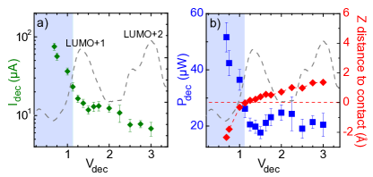
A current drop as in Figs. 2(a) and 2(b) provides the position Z and current I at which molecular decomposition occurs. Both Z and I depend strongly on the bias value V used. In Fig. 3(a) we plot the statistical average of I as a function of V between 0.6 V to 3.0 V. For V= 3.0 V an electron current I= 7 A suffices to produce the C60 degradation. This occurs when the tip is still more than 1 Å away from the contact position, i.e. in tunnel regime. As V is reduced I increases gradually (with a small plateau around 1.5 eV and 2.5 eV) and, accordingly decomposition occurs with the tip closer to the fullerene, but still in the tunnel regime (i.e. with I(Z) curves as in Fig. 2(a)). For V below 1.2 V a more pronounced increase of I is observed when approaching the tip. In this range the onset of tip-C60 contact is already detected in the I(Z) plots (as in Fig. 2(b)). Electron currents as high as 70 A can flow through the molecular junction for the lowest bias achieving degradation (V 0.6 V). In this regime the STM tip indents more than 2 Å beyond the contact position. However, we can rule out a mechanical process of rupture because below the threshold bias of 0.6 V C60 remains unaffected upon tip indentations of more than 4 Å (see Fig. 1(c)). Instead, we note that C60 undergoes a thermal decomposition on metal surfaces at temperatures around 1000 K CepekPRB96 ; PascualSS97 ; Swami99 ; Saltas01 . Thus, we consider that the decomposition of C60 is a current-driven thermal process, where the critical current depends crucially on the applied voltage.
The two different regimes of molecular decomposition in tunnel and in contact as suggested by the behavior of I with V in Fig. 3(a) become more evident when we plot the power P (P I V) applied to the C60 junction for its degradation (Fig. 3(b)). In tunnel regime, i.e. above V 1.2 V, P amounts to 20 W and shows small oscillations at the LUMO+1 and LUMO+2 position. For lower bias P increases sharply up to more than 50 W, reflecting that here the junction can sustain larger current densities. It should be noted that in this regime decomposition is attained when the tip is in contact with the molecule. Hence, the very sharp change in P as compared to the oscillations in P around higher molecular resonances suggests that the contact plays an important role for the decomposition process.
The origin of molecular dissociation in the two different transport regimes can be rationalized from a conceptual definition of molecular temperature. The electron tunneling rates used to decompose the C60 molecule (a few fs-1) are larger than typical phonon decay rates for adsorbate systems. Hence, we consider a current-induced vibrational heating, in which C60 vibrations are excited in a non-equilibrium distribution Salam94 ; Gao97 . For a certain set of current and bias values, the total vibrational energy U stored in the molecule (and hence its temperature T) depends on the balance between the heat generated by the inelastic scattering of electrons with molecular modes, and heat dissipation into the “cold” leads (T=5K) PecchiaPRB07 ; NitzanJPCM07 ; PecchiaJCM07 . Following this picture, a larger degradation power P is due to either a less effective heat generation or to a more effective dissipation of heat into the leads.
In order to analyze and corroborate the influence of the resonances and the tip-molecule contact theoretically we have performed model transport calculations based on the Non-Equilibrium Green’s Function (NEGF) formalism Pecchia2 ; Gagliardi . The C60 molecule is relaxed on a slab of 8 layers of copper in a 4 x 5 unit cell using density functional theory calculations vdWaals . The resulting structure is in good agreement with experiments FaselPRB99 . Unoccupied molecular states (LUMO, LUMO+1 and LUMO+2) are located at 0.7 V, 1.5 V and 3.0 V above the Fermi level, respectively. The tip is represented by a Cu atom adsorbed on a jellium surface.
Inelastic electron scattering in C60 is calculated using the Self Consistent Born Approximation (SCBA) BAapprox . The non-equilibrium phonon population, (where the q index runs over all 174 normal modes of vibration of the C60), is deduced from a rate equation including the phonon absorption (A) and emission probabilities (E) in the device calculated as in ref. PecchiaJCM07 . A “model” molecular temperature, T, can be associated to the internal energy, , by assuming a Bose-Einstein phonon population that produces the same internal energy as the non-equilibrium population note1 .
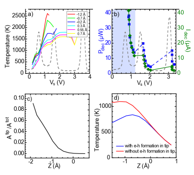
Fig. 4 (a) shows the effect of increasing the applied bias on the molecular temperature T. For the experimental values of tip-molecule distance, the applied bias leads to a heating of the molecule up to temperatures above 1000 K. Such high temperatures are reached with only a small fraction of electrons being inelastically scattered by molecular vibrons ( 10-3). The heating becomes more effective when the LUMO resonance enters in conduction due to resonant electron-phonon emission PecchiaPRB07 . The temperature increase is largest when all C60 vibrational modes can be excited, which lie in a band of 200 meV width above the resonance. A similar rise in T appears at bias values when higher order resonances enter into conduction. Contrary to this, phonon assisted tunneling contributes to cooling the C60 molecule right below the resonances, causing in total a modulated rise in T.
To simulate the experimental curves of Fig. 3, we set a critical temperature for decomposition, T, and obtain from Fig. 4(a) the corresponding set of values V and Z. From the I-V characteristics we then extract the corresponding I. For T 1650 K the applied power is similar to the experimental values note5 . For bias values larger than 1.2 V the decomposition takes place in the tunnel regime and a step-like behavior is obtained for I. Where I remains constant P increases, thus producing the oscillations shown in Fig. 4(b). These reflect the resonant phonon cooling and heating below and above a resonance, respectively. Such oscillations resemble the experimental oscillations of P at the LUMO+1 and LUMO+2, hence confirming a resonance mediated mechanism of molecular heating in tunneling.
This, however, does not explain the very large increase in P for sample bias below 1.2 V. Here, as in the experiment, molecular decomposition is achieved once the tip is in contact with C60. The formation of a tip-molecule contact enhances the dissipation of vibrations from the hot molecule into the cold tip. There are two possible mechanisms of mode quenching: vibrational decay due to vibron-phonon coupling and to electron-hole (e-h) pair excitations. Our calculations also suggest that the former plays a small role in the cooling effect, since the phonon bands at the leads are much narrower than the 200 meV wide C60 vibrational spectrum. On metal surfaces, instead, the main mechanism is the e-h excitation in the leads Gao92 . From our calculations we can estimate the contribution of e-h pair creation in the tip by extracting the corresponding phonon absorption rate (A) noteAq . Molecular mode quenching becomes only important in the proximity of contact formation and further indentation in the molecule as revealed by the monotonous increase of A (Fig.4(c)). The effect on T can be determined by setting A to zero and calculating again the effective temperature. Fig. 4(d) evidences that the temperature thus determined increases much faster when approaching the tip towards the molecule than in the case where e-h excitation in the tip is allowed. Hence, our calculations strongly support that the sharp increase in both I and P result from phonon cooling upon contact formation. At low bias, the LUMO resonance starts to be removed from the conduction window and, as shown in Fig. 4(a), the molecular temperature decreases drastically. This explains that the thermal decomposition cannot be achieved in the experiment below 0.6 eV.
In summary, our results reveal that resonant tunneling through molecular states in a single molecule device can generate sufficient heat to thermally decompose the molecular junction. For the case of a C60 molecule on a Cu(110) surface, a power of only 20 W is sufficient. In order to increase the current density a molecular junction can sustain, it would be useful to remove molecular resonances from the transport window. However, in most cases the molecular device properties rely crucially on molecular resonances, and hence cannot be engineered without loosing the functionality. Good contact of the molecule with the leads then opens the possibility for the single molecule device to withstand larger current densities.
This research was supported by the Deutsche Forschungsgemeinschaft, through the collaborative projects SPP 1243 and SFB 658.
References
- (1) A. Aviram and M. Ratner, Chem. Phys. Lett. 29, 277 (1974).
- (2) M. Galperin, M. A. Ratner and A. Nitzan, J. Phys.: Cond. Matt. 19, 103201 (2007).
- (3) M. Galperin, A. Nitzan and M. A. Ratner, Phys. Rev. B 75, 155312 (2007).
- (4) A. Pecchia, G. Romano, and A. Di Carlo, Phys. Rev. B 75, 035401 (2007).
- (5) Z. Huang et al., Nano Letters 6, 1240 (2006).
- (6) Z. Huang et al, Nature Nanotechnology 2, 698 (2007).
- (7) N. Neel et al., Phys. Rev. Lett. 98, 065502 (2007).
- (8) J. M. Tour, Acc. Chem. Res. 33, 791 (2000).
- (9) R. Fasel et al., Phys. Rev. B 60, 4517 (1999).
- (10) These values remain down to the onset of a tip-molecule contact.
- (11) Indenting the tip into clean surface areas ensures the tip apex to consist of Cu atoms.
- (12) C. Joachim et al., Phys. Rev. Lett. 74, 2102, (1995).
- (13) Y. B. Zhao et al., Appl. Phys. Lett. 64, 577, (1994).
- (14) C. Cepek, A. Goldoni and S. Modesti, Phys. Rev. B 53, 7466 (1996).
- (15) J. I. Pascual, J. Gomez-Herrero, and A. M. Baro, Surf. Sci. 397, L267 (1998).
- (16) N. Swami, H. He, and B. E. Koel, Phys. Rev. B 59, 8283 (1999).
- (17) V. Saltas and C. A. Papageorgopoulos, Surf. Sci. 488, 23 (2001).
- (18) S. Gao, Phys. Rev. B 55, 1876 (1997).
- (19) G. P. Salam, M. Persson, and R. E. Palmer, Phys. Rev. B 49, 10655 (1994).
- (20) G. Romano, A. Pecchia and A. Di Carlo, J. Phys.: Cond. Matt. 19, 215207 (2007).
- (21) A. Pecchia and A. Di Carlo, Rep. Prog. Phys. 67, 1497, (2004).
- (22) A. Gagliardi et al., Phys. Rev. B 75, 174306, (2007).
- (23) M. Elstner et al., J. Chem. Phys. 114, 5149, (2001).
- (24) We approximate the molecular by fitting the total atomic kinetic energy to a Bose-Einstein distribution at temperature T. A better approach employs a fictitious external phonon bath to ”measure” T NitzanJPCM07 . Qualitatively, both methods are similar.
- (25) M. Galperin, M. Ratner and A. Nitzan, Nano Lett. 4, 1605, (2004).
- (26) Th. Frauenheim et al. J. Phys.: Cond. Matt. 14, 3015, (2002).
- (27) M. Elstner et al., Phys. Rev. B, 58, 7260, (1998).
- (28) S. Gao, M. Persson, and B. I. Lundqvist, Solid State Comm. 84, 271, (1992).
- (29) No qualitative difference is seen in the results if T is increased by several hundreds of degrees or by using U as a critical parameter for molecular decomposition.
- (30) The excitation of an e-h pair in the tip can be seen as a real process in which an electron from the tip absorbs a phonon and is reflected back into the tip: A, where is the electron-phonon coupling matrix, is the projected density of states on C60+tip states, and is the tip Fermi function.
- (31) I. Horcas et al., Rev. Sci. Instrum. 78 , 013705 (2007).