Fibre coupled dual-mode waveguide interferometer with /130 fringe spacing
Abstract
Predictions and measurements of a multimode waveguide interferometer operating in a fibre coupled, “dual-mode” regime are reported. With a 1.32 m source, a complete switching cycle of the output beam is produced by a 10.0 nm incremental change in the 8.0 m width of the hollow planar mirror waveguide. This equates to a fringe spacing of . This is an order of magnitude smaller than previously reported results for this form of interferometer.
pacs:
42.25.Bs, 42.25.Hz, 42.79.GnThe propagation of light through rectangular and planar multimode waveguides can result in interesting self-imaging effects based on multimode interference (MMI) phenomena 1 ; 2 . Over the last decade or so, these effects have been demonstrated as the basis of splitters 3 ; 4 ; 5 , modulators and switches 6 , Mach-Zehnder interferometers 7 and laser resonators 8 .
More recently, Ovchinnikov and Pfau 9 (see also reference 10 ) have described a novel form of multimode waveguide interferometer based on a planar waveguide formed from a pair of fully reflecting mirrors. Light enters the planar waveguide at some angle exciting a spectrum of modes. The ensuing multimode propagation and interference result in oscillations and revivals in the transverse momentum of the propagating field 9 . If is the length of the multimode guide, is the wavelength of the injected radiation, and is an integer number, then a guide width maximises the magnitude of the momentum oscillations at the guide exit. Under this condition, small changes in guide width cause the output beam to swing back and forth between the angles of .
In their experiment, Ovchinnikov and Pfau 9 coupled a 2.0 mm diameter beam from a 0.633 m source into a 50.0 mm long planar waveguide at an angle of 0.25 radian. With a waveguide width of 30 m, a complete cycle of the angular deviation of the output beam was produced by a 70.0 nm change in guide width. The sensitivity to the change in guide width equated to a fringe spacing of 9 . This is substantially smaller than that achieved with a Michelson interferometer.
Although this result is impressive, Ovchinnikov and Pfau 9 suggested that narrower guide widths () should lead to improved sensitivity. They also alluded to the interesting case where only two modes are excited in the planar multimode waveguide, suggesting that the resulting fringe characteristic should be uniform and periodic. If this situation could be realized in practice, then the interferometer could be used over a broader range of contiguous mirror spacings as there would be no ”collapse” phenomena to impair operation. Furthermore, with the excitation of only the two lowest order modes, the attenuation in the planar mirror waveguide would be minimized. This is important as, what ultimately limits the sensitivity of this form of interferometer, are the larger attenuation coefficients of the higher order modes.
In this Letter, we show how to implement the proposed dual mode operational regime. Our experimental configuration (see Fig. 1) was similar to that used by Ovchinnikov and Pfau 9 .
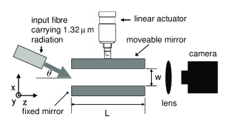
The planar multimode waveguide was formed by two 50.0 mm diameter fully reflecting gold coated mirrors both having a surface figure of /10 at 632.8 nm. One of the mirrors was held in a fixed precision mount, the other was mounted on a linear actuator. In our case, 1.32 m radiation from a Nd:YAG laser source was coupled to the planar waveguide from a single-mode, polarization maintaining fibre with an effective 1/e2 TEM00 mode diameter of 6.5 m. The fibre was held straight in a fibre guide and adjusted so that the polarization orientation of the output field was parallel to the plane of the mirror surfaces, i.e. parallel to the y-axis in Fig. 1. Initially the fibre axis was aligned to be co-linear with the planar waveguide axis and butted up to it. Under this condition a choice of m, maximizes the power coupling to its fundamental mode 11 . From this starting point, the fibre was tilted by an angle with respect to the axis of the planar waveguide. In practice, although the last centimeter of the fibre was stripped back to its 125 m cladding diameter, this still meant that the axis of the fibre pivoted about a 62.5 m radius. Depending on the magnitude of , this leads to a short free-space propagation distance and some diffraction before the beam enters the planar waveguide. This was taken into account in the overlap integral calculations to obtain the power coupling coefficients as a function of the input angle (see Fig. 2).
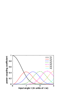
As increases, modes of higher order are excited in turn. The peak in the excitation characteristic of any given higher order mode occurs when the angle of incidence of the input field corresponds to the angle of one of the plane wave components of the higher order mode itself. To a good approximation, to maximize the excitation of the TEp-th mode, an input beam angle of is required. Hence for , one obtains radian. As indicated in Fig. 2, by choosing an input angle of half this magnitude, i.e. radian, the excitation is essentially limited to two modes, TE1 and TE2.
Under this condition, we calculate the sensitivity of the output field to changes in guide width. The phase change between any two TE modes following propagation through an axial distance , is given by: where, is the phase coefficient of the TEp mode:
| (1) |
Under the condition , we get
| (2) |
Putting and for the modes TE1 and TE2 respectively, differentiating with respect to the guide width and rearranging, yields:
| (3) |
Equating Eq. 3 to gives the incremental change in guide width that will produce a phase change between the modes, and hence, a change in the output beam angle from to , and back again, i.e. a fringe, as
| (4) |
Eq. 4 leads us to conclude that small guide widths in conjunction with long waveguides and long wavelength radiation produce maximum sensitivity. However, reducing the guide width and increasing both the guide length and the wavelength also cause the attenuation of the excited modes to increase in a differential manner. As shown below, this will affect the power ratio between the modes and impact on our ability to measure variations in the output field due to incremental changes in guide width.
The fractional power transmission for the mode TEp through a planar waveguide of length is given by
| (5) |
Here, is the attenuation coefficient and is the complex refractive index of the wall material. For a 1.32 m source in conjunction with a 50 mm long planar waveguide formed from gold ( and ) coated mirrors, Eq. 5 yields . For m, this yields fractional transmission values for the modes TE1, TE2 and TE3 of 0.23, 0.0028 and 1.85 respectively, with . For m, the corresponding values are 0.68, 0.22 and 0.03, with . From this perspective, with the aim of working with small guide widths in order to achieve high sensitivity, we refer back to Fig. 2 and opt for an input angle of . This provides the highest starting magnitude of TE2, while the additional excitation of the modes TE3 and TE4 are of little consequence because of their significantly higher attenuation.
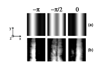
On the aforementioned basis, we started off with a guide width of 11.0 m with the aim of making measurements of interferometer sensitivity as the width was decreased to 8 m. The launch angle was kept fixed at 0.14 radian corresponding to a median guide width of 9.25 m. To start with, the mirrors were very accurately aligned with respect to one another to ensure that they were parallel. To aid in this process and confirm that dual mode operation was achieved in practice, a magnified ( 100 times) image of the field generated at the exit of the multimode waveguide interferometer was produced with a microscope objective and viewed with a Hamamatsu infrared vidicon camera C2400-03. The latter has an operational waveband of 0.8 - 2.1 m and a resolution of 720 576 pixels. For a guide width of 11 m and an input angle of 0.14 radian, our predicted transverse intensity profiles at the exit of the planar waveguide are shown in Fig. 3a. These correspond to a TE1:TE2 output power ratio of and phase differences of , and radians induced between these modes by the displacement of the moveable mirror. Fig. 3b shows the results of equivalent measurements made with the camera. The widths of the images correspond to the starting multimode guide width of 11 m while the heights correspond to 100 m high segments of the total vertical extent of the output fields. As a consequence of magnification, the physical dimensions of the images in Fig. 3b are 1.1 x 10 mm. For presentational purposes, the heights of the images have been compressed by a factor of three. The very good agreement between the measured and predicted field intensity contours confirms that dual mode operation was achieved in practice.
In order to demonstrate that dual mode operation was achieved over a wide range of contiguous mirror spacings without the presence of the “collapse” phenomena associated with multimode operation, we made a further measurement. This involved accurately locating an InGaAs photo-detector with an effective diameter of 1.0 mm in the plane of the magnified image of the output field. The detector was offset from the axis of the planar multimode waveguide such that its active area only captured light from one side of the image. A linear voltage ramp was then applied in an incremental manner to our Newport ESA 1330 electro-strictive actuator. At the same time the output from the photo-detector was digitized and recorded. The starting value, and the magnitude of the applied voltage ramp, was chosen to correspond to the most linear portion of the displacement versus applied voltage characteristic of the actuator and to change the planar guide width from an initial value of 11 m to a final value of 8 m. The tolerance on the resulting guide width was estimated to be 0.5 m. A plot of the detector output amplitude as a function of the guide width is illustrated in Fig. 4.
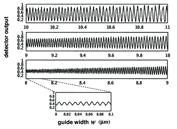
A continuous fringe characteristic is observed. Despite decreasing visibility, it exists over many periods () and exhibits no collapse phenomena. The bottom figure of the experimental data set illustrates a higher resolution plot indicating a fringe spacing of 10 nm with a guide width of 8 m. The decreasing visibility of the fringes with decreasing guide width is a consequence of increased aperturing at the entrance plane, the larger attenuation of both modes, and the higher relative attenuation of the TE2 mode compared with the fundamental. For values of guide width much below 8.0 m the TE2 mode amplitude is so small that the fringe visibility becomes comparable with concatenated measurement noise.
In order to more accurately confirm the sensitivity of the interferometer, a further measurement was undertaken. This involved making use of the fringe characteristic itself to calibrate the change in guide width produced by the actuator against a high precision micrometer which was incorporated on the same translational stage. With the actuator calibrated in this manner the applied voltage was changed manually in order to produce ten complete fringe cycles (of the form shown in Fig. 3b) as observed directly on the vidicon camera with the naked eye. Using this approach, the error in the measurement of the incremental change in guide width necessary to produce a complete switching cycle of the output field was estimated to be of the order of 2.0 nm
As illustrated in Fig. 5, these results were plotted as a function of absolute guide width (measured to an estimated accuracy of 0.5 m) together with a theoretical prediction based on Eq. 4.
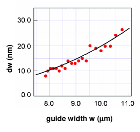
With a guide width of 8.0 m, the measured incremental change in guide width required to produce a complete switching cycle of the output beam was 10.0 nm in agreement with the earlier result. For our 1.32 m source, this equates to a change in guide width of /130.
In conclusion, an improved multimode waveguide interferometer of the form originally conceived by Ovchinnikov and Pfau 9 has been demonstrated. Our implementation differs from previous work 9 in three main ways: (i) a fibre is used to more efficiently couple the light from the laser source into the planar waveguide, thereby significantly reducing aperturing losses; (ii) the choice of the TEM00 waist diameter and the input angle, coupled with the differential attenuation of the excited modes, ensures that only the two lowest order modes (TE1 and TE2) are present at the exit plane of the planar waveguide. This leads to the lowest possible attenuation in the waveguide and circumvents the problems of revival and collapse phenomena associated with the excitation of more than two modes 9 . Finally, (iii) the changes in the transverse mode output from the interferometer are measured in the near field. With this implementation a complete cycle of the output field pattern was produced by an incremental change in guide width of 10.0 nm or /130. This should be compared with the /9 change in guide width required to produce a full switching cycle demonstrated in earlier work 9 .
A simple analytical expression, given by Eq. 4, has been derived for the sensitivity of the dual-mode interferometer and the way it scales with guide width, guide length and wavelength. Using Eq. 4, predictions of the incremental change in guide width required to produce a complete switching cycle of the output beam are found to be in good agreement with the experimentally measured results as illustrated in Fig. 5.
With respect to achieving higher sensitivity, because of the dependence of the attenuation coefficient in Eq. 5, we conclude that it is best to use the shortest operational wavelength possible and, in relation to Eq. 4, to compensate for this by using longer guides and smaller guide widths. Further reduction in attenuation (and hence improved sensitivity) might also be achieved with multilayer mirror coatings designed to provide very high reflectivity for grazing angle incidence TE fields.
We end by noting that dual-mode excitation could also be produced by a laterally offset TEM00 beam or by a suitably offset fundamental mode field from an input waveguide. As in the approach described herein, this would result in an output field whose intensity maximum switches from one side of the guide exit to the other. This could be measured with a single or dual-element detector placed directly at the guide exit. This arrangement would make the interferometer more compact facilitating its realisation in silicon based MEMS technology. Thus, multimode waveguide interferometers of the type originally proposed by Ovchinnikov and Pfau 9 should find many sensor and switching applications in the more efficient and more sensitive fibre-coupled dual-mode regime, demonstrated in this paper.
References
- (1) O. Bryngdahl, J. Opt. Soc. Am. 63, 416 (1973).
- (2) R. Ulrich and G. Ankele, Appl. Phys. Lett. 27, 337 (1975).
- (3) R. M. Jenkins, R. W. J. Devereux, and J. M. Heaton, Opt. Lett. 17, 991 (1992).
- (4) J. M. Heaton et al., Appl. Phys. Lett. 61, 1754 (1992).
- (5) Y B Ovchinnikov, Opt. Comm. 182, 35 (2000); 220, 229 (2003).
- (6) R. M. Jenkins, J. M. Heaton and D. R. Wright, Appl. Phys. Lett. 64, 684 (1994).
- (7) R. M. Jenkins, R. W. J. Devereux, and J. M. Heaton, Opt. Comm. 110, 410 (1994).
- (8) J. Banerji, R. M. Jenkins, and A. R. Davies, Appl. Opt. 36, 1604 (1997); J. Opt. Soc. Am. 14, 2378 (1997); Appl. Opt. 44, 3364 (2005).
- (9) Y B Ovchinnikov and T Pfau, Phys. Rev. Lett. 87, 123901 (2001).
- (10) Y B Ovchinnikov, ”A multimode waveguide interferometer”, in Focus on Lasers and Electro-Optics Research, Ed. W.T. Arkin, pp. 169-185, Nova Science Publishers, New York (2004).
- (11) D. M. Henderson, Appl. Opt. 15, 1066 (1976)