Comment on “Guiding, focusing, and sensing on the subwavelength scale using metallic wire arrays”
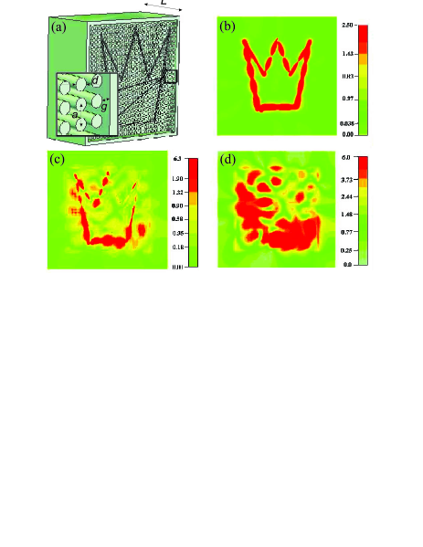
In a recent Letter, Shvets et al Shvets et al. (2007) describe a multiwire endoscope and claim that it is capable of guiding electromagnetic field distributions preserving their subwavelength details. The letter contains results of simulations for endoscope consisting of array of wires and a claim that ‘a practical multichannel endoscope will have a much larger (e.g. ) number of metal wires’. We performed numerical simulation of the multiwire endoscope (see Fig.1a) with exactly the same parameters as suggested by Shvets et al using CST Microwave Studio package and didn’t observe a satisfactory imaging performance (see Fig.1d).
Previous theoretical and experimental studies of multiwire transmission devices Belov et al. (2005, 2006); Belov and Silveirinha (2006); Belov et al (2006); Silveirinha et al. (2007) which were ignored in Shvets et al. (2007) allows us to conclude that endoscope does not operate properly because of two reasons. Firstly, the endoscope is coated by metal, when such kind of shielding actually greatly reduces and limits its performance. In the absence of shield the imaging performance of the endoscope would be greatly increased. Secondly, an array of metallic wires can be efficiently used for sensing, guiding and focusing in the subwavelength scale, only if the length of the wires is tuned to obey the Fabry-Perot (FP) resonance condition. This requirement is not fulfilled in Shvets et al. (2007) whereas it is of fundamental importance in order that the fields can be effectively sensed by the endoscope.
In subwavelength structures the electric field can be described to a good approximation by an electric potential. The multiwire system basically behaves as a “sampler” of electric potential. Such property implies that the period of the array roughly determines the resolution of the system. However, the presence of the metal shield forces the electric potential to be constant around a circumference very close to the object to be imaged. This implies that the electric field distribution near the considered object is corrupted by the presence of the endoscope (see Fig. 1c). In the other words, diffraction on the metal shield is extremely harmful to the image formation. This problems can be avoided by using a multiwire endoscope with no metallic shield and thickness tuned to obey FP resonance condition. In this case, as demonstrated in Zhao et al. (2006), because of the all-spatial-spectrum FP resonance the multiwire endoscope does not produce any diffraction effects.
Basically, the multiwire system must be operated in the “canalization” regime described in Belov et al. (2005). The key idea is to transform the whole spectrum of spatial harmonics generated by the source, including evanescent waves, into propagating eigenmodes of a metamaterial. This enables transmission of any field with subwavelength details from the front interface of the metamaterial slab to the back one provided the thickness of the slab obey the FP resonance condition. Such regime was studied in detail at the microwave Belov et al. (2005); Ikonen et al (2006); Belov et al. (2006); Belov and Silveirinha (2006); Belov et al (2006), infrared Silveirinha (2006); Silveirinha et al. (2007) and even visible Belov and Hao (2006) domains. It has been used for realization of subwavelength imaging by photonic crystals, and in this context it is also known as self-collimation Witzens et al. (2002); Li and Lin (2003); Garcia-Pomar and Nieto-Vesperinas (2005), directed diffraction Chien et al (2004) and tunneling Kuo and Ye (2004). It is well established Belov et al. (2006); Belov and Silveirinha (2006); Belov et al (2006); Silveirinha et al. (2007); Silveirinha (2006) that an array of metallic wires can be operated in the canalization regime up to infrared frequencies due to the extraordinary waveguiding properties of the quasi-TEM mode supported by the metallic wires, and that such effect is weakly dependent on losses and on the plasmonic properties of the metal Silveirinha et al. (2007); Silveirinha (2006).
The FP condition enhances the sensing properties of the wires, enables a nearly perfect transmission of the image, and guarantees the absence of strong reflections from the endoscope, which otherwise perturb the near field distribution of the source (see Fig.1c). Numerous numerical and experimental studies Belov and Silveirinha (2006); Belov et al (2006); Silveirinha et al. (2007) show that if the frequency of operation is significantly away from FP resonance then the image is severely distorted by surface waves (see Fig.1d). This is a very general behavior, a characteristic of arrays of parallel wires, ad of tapered arrays, as shown in Ikonen et al (2007) where a three fold magnification was demonstrated using an array of wires.
References
- Shvets et al. (2007) G. Shvets, S. Trendafilov, J. B. Pendry, and A. Sarychev, Phys. Rev. Lett. 99, 053903 (2007).
- Belov et al. (2005) P. A. Belov, C. R. Simovski, and P. Ikonen, Phys. Rev. B. 71, 193105 (2005).
- Belov et al. (2006) P. A. Belov, Y. Hao, and S. Sudhakaran, Phys. Rev. B 73, 033108 (2006).
- Belov and Silveirinha (2006) P. A. Belov and M. G. Silveirinha, Phys. Rev. E 73, 056607 (2006).
- Belov et al (2006) P. A. Belov et al, Appl. Phys. Lett. 89, 262109 (2006).
- Silveirinha et al. (2007) M. Silveirinha, P. Belov, and C. Simovski, Phys. Rev. B 75, 035108 (2007).
- Zhao et al. (2006) Y. Zhao, P. Belov, and Y. Hao, Optics Express 14, 5154 (2006).
- Ikonen et al (2006) P. Ikonen et al, Phys. Rev. B 73, 073102 (2006).
- Silveirinha (2006) M. Silveirinha, Phys. Rev. E 73, 046612 (2006).
- Belov and Hao (2006) P. Belov and Y. Hao, Phys. Rev. B 73, 113110 (2006).
- Witzens et al. (2002) J. Witzens, M. Loncar, and A. Scherer, IEEE Journal of Selected Topics in Quantum Electronics 8, 1246 (2002).
- Li and Lin (2003) Z.-Y. Li and L.-L. Lin, Phys. Rev. B 68, 245110 (2003).
- Garcia-Pomar and Nieto-Vesperinas (2005) J. L. Garcia-Pomar and M. Nieto-Vesperinas, Optics Express 13, 7997 (2005).
- Chien et al (2004) H.-T. Chien et al, Phys. Rev. B 70, 113101 (2004).
- Kuo and Ye (2004) C.-H. Kuo and Z. Ye, Phys. Rev. E 70, 056608 (2004).
- Ikonen et al (2007) P. Ikonen et al, Appl. Phys. Lett. 91, 104102 (2007).
—————————–7d8fa261305c2–