BES3 time of flight monitoring system
Abstract
A Time of Flight monitoring system has been developed for BES3. The light source is a 442-443 nm laser diode, which is stable and provides a pulse width as narrow as 50 ps and a peak power as large as 2.6 W. Two optical-fiber bundles with a total of 512 optical fibers, including spares, are used to distribute the light pulses to the Time of Flight counters. The design, operation, and performance of the system are described.
keywords:
Time-of-flight monitoring; Laser diode; Fiber opticsPACS:
42.60.By, 42.55Px, 42.72.Bj, 42.81.-iF. A. Harris , J. W. Kennedy, Q. Liu, L. Nguyen, S. L. Olsen, M. Rosen, C. P. Shen, G. S. Varner Y. K. Heng, Z. J. Sun, K. J. Zhu
Q. An, C. Q. Feng, S. B. Liu
1 Introduction
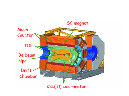
The Beijing Electron-Positron Collider (BEPC) and the Beijing Spectrometer (BES) [1, 2] have operated in the tau-charm center-of-mass energy region from 2 to 5 GeV since 1990. Currently they are being upgraded to BEPCII and BES3 [3, 4, 5], respectively. BEPCII is a two-ring collider with a design luminosity of cm-2 s-1, an improvement of a factor of 100 with respect to the BEPC. BES3, shown in Fig. 1, is a new detector and features a beryllium beam pipe; a small-cell, helium-based drift chamber (MDC); a Time-of-Flight (TOF) system; a CsI(Tl) electromagnetic calorimeter; a 1 Tesla super conducting solenoidal magnet; and a muon identifier using the magnet yoke interleaved with Resistive Plate Chambers. Particle identification is accomplished in BES3 using measurements in the MDC and TOF measurements.
In this paper, we report on the development and performance of a laser diode based TOF monitoring/calibration system. Pulses of light from the laser diode are injected into one of two optical fiber bundles, one for each end of the BES3 detector, and the light is delivered by the individual optical fibers to the TOF counters. The laser is pulsed under computer control, and the bundle being illuminated is also under computer control. The digitized responses from the phototubes mounted on the TOF counters are then checked and compared with a database. This allows monitoring of the performance of the TOF system.
2 Time-of-Flight System
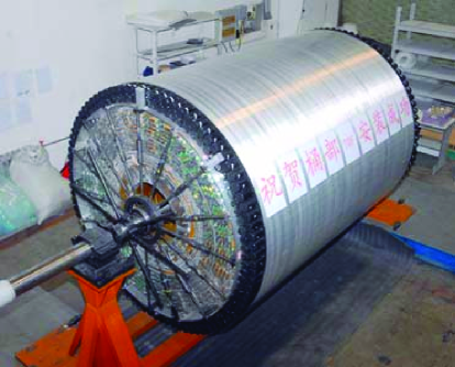
The TOF system, which is crucial for particle identification, is an array of plastic scintillation counters, that measure the relative arrival times of particles coming from electron-positron annihilations generated by the BEPCII Collider. It is composed of a barrel array with 88 scintillation counters in each of two layers, and endcap (EC) arrays with 48 fan shaped scintillators in each. The barrel counters are Bicron 408 scintillator of 2300 mm length and with a trapeziodal cross section. The endcap scintillators are Bicron 404. All TOF counters are read out using Hamamatsu R5942 fine mesh phototubes, two phototubes on the barrel counters (one on each end) and one on the endcap counters. Figure 2 shows the barrel TOF counters mounted on the outside of the MDC before installation into the electromagnetic calorimeter. The intrinsic time resolution for 1 GeV/ muons with one TOF layer is less than 90 ps, which has been confirmed using these counters and prototype BES3 electronics [6] and using cosmic rays through the final TOF array and read out system.
3 Light source
The light source is a PicoQuant PDL 800-B pulsed laser driver with a LDH-P-C-440M laser diode head. The wavelength of this head is 442 - 443 nm, and the pulse width for low power operation is 50 ps FWHM and for high power approximately 500 ps FWHM. Critical here is not the pulse width but the peak power. For the maximum power setting of the laser driver, the peak power is 2.6 W, which provides enough photons for our purposes. The driver can operate at 40, 20, 10, 5 or 2.5 MHz and can also be externally triggered, making the unit convenient for use in the BES3 calibration environment.
The advantages of the laser diode compared, for instance, to a nitrogen-dye laser used in previous systems [7] are ease of operation, minimal maintenance, stability, and long lifetime. The laser head has Peltier cooling, and the power stability over a 12 hour period is 1 % RMS.
The laser head emits a collimated elliptical beam of approximately 1.5 mm 3.5 mm and with divergence angles of 0.32 mrad parallel to and 0.11 mrad perpendicular to the long axis of the beam. The beam is 90 % linearly polarized, perpendicular to the long axis of the elliptical beam.
4 Optical fiber bundles

Light from the laser diode is injected into one of two optical fiber bundles, one for each end of the BES3 detector. Each bundle contains 256 optical fibers, including spares. The optical fibers are multimode, stepped-index, low UV attenuation (about 3 dB/km at 440 nm) fibers, made from high OH- silica for both the core and cladding, and they have a 100 micron core diameter, a 110 micron cladding diameter, and a 125 micron polymide buffer diameter. The numerical aperture is 0.22.
At the input end of these bundles, the optical fibers without jacketing are closely packed into a circular cross section, which is approximately 2.25 mm in diameter. The ratio of the core diameter to the buffer diameter is large enough that the light coupling into the fibers is reasonably efficient. A 6.35 mm outer diameter by 5.0 cm long custom ferrule here provides good concentricity between the core bundle and its outside diameter and is mechanically substantial enough to clamp to. The ferrule is filled with epoxy, and the optical fiber ends are polished.
At the back of the ferrule, the fibers are contained in a 20 cm long PVC Monocoil tube that connects to a 7.5 cm long stainless steel ferrule. Inside this ferrule the 256 fibers transition into 32 PVC Furcation Tubing jacketed cables with 8 fibers per cable. At a distance of 9.0 m from the input ferrule, the 32 cable main bundle divides into four sub-bundles that terminate at the fan-out locations, as shown in Fig. 3. Of the four sub-bundles, two are used to illuminate one end of the barrel TOF counters. These sub-bundles, 6.0 m in length, have 96 fibers each contained in 12 PVC Furcation tube jacketed cables that terminate at 8-fiber MTP connectors connected to optical-fiber couplers inside a distribution box. The 12 cables are captured in a mounting flange at the entrance to the box, and strain relief for the fibers is provided. The distribution boxes allow a transition to easily replaceable delivery optical fiber cables in the region of the detector where the cables are most likely to be broken.
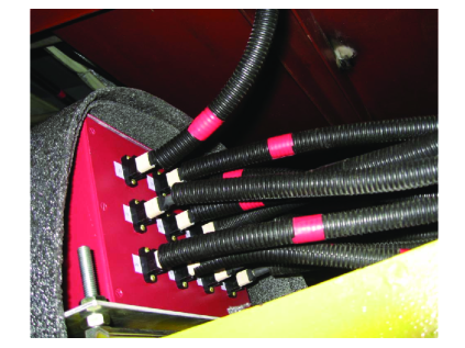
Delivery fiber cables with 8 optical fibers and an MTP connector mate on the outside of the distribution box, as shown in Fig. 4. The cables are 9.0 m in length, but split into individual fiber cables after 5.0 m. These cables are jacketed with PVC Furcation Tubing and terminate in a custom ferrule (described below) that delivers light to the TOF counters. Mechanical strain relief is provided wherever main bundles divide into sub-bundles and/or individual optical fiber cables.
The other two sub-bundles are used to illuminate one end of the endcap TOF counters. These bundles, 9.5 m in length, have 32 fibers each divided among four cables of 8 fibers that terminate at 8-fiber MTP connectors. These MTP connectors connect to optical-fiber couplers on the outside of endcap distribution boxes, one of which is shown in Fig. 5.
Four delivery fiber cables with 8 optical fibers and an MTP connector connect to the couplers on the inside of the box. The cables are 2.5 m in length, but split into individual fiber cables after 1.0 m. These cables terminate in custom ferrules at the end that deliver light to the endcap TOF counters.
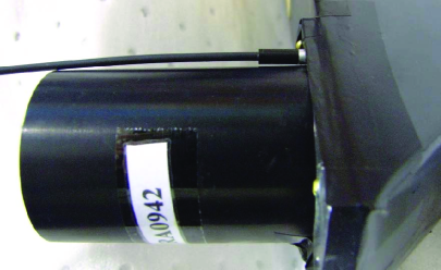
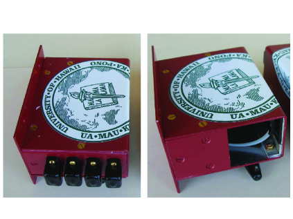
If access is required to the central detector, for instance to fix barrel TOF phototubes or electronics or MDC electronics, the endcaps need to be opened. This requires that the endcap optical fiber bundles are able to be reliably disconnected and reconnected. The two endcap distribution boxes mount on the back of the endcap. The size of each box is limited to 40 mm x 80 mm x 100 mm (see Fig. 5). Both of these constraints necessitate the use of compact multi-optical-fiber connectors here.
Spare optical fibers were included in the design of the main bundles, in the event that breakage occurs during fabrication or installation. There are a total of 32 spare optical fibers out of 256 total optical fibers (= 12.5% spares). Spare delivery fiber cables for both the barrel and endcap distribution boxes were also purchased.
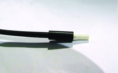
Figure 6 shows the ferrule that is common for all TOF counters. The ferrule tip is zirconia and the length and diameter of the tip are mm and mm, respectively. The 1.27 cm long transition tube is Delrin with a diameter of 4.75 mm. The ends of the ferrules have a standard fiberoptic polish. The ferrules are inserted into holes within the mounting flanges of the phototubes, as shown in Fig. 7, and are glued in place with a silicon adhesive. For the endcap counter, one of which is shown in Fig 7, the light is injected on the top of the counter, and some reflects off the bottom of the counter up into the PMT. For the barrel counters, the light is also injected into a hole in the mounting flange of each PMT and travels the length of the scintillator into the other PMT.
5 Laser box
The laser box houses the laser diode head, two compact Hamamatsu R7400U series reference photo multipliers (PMTs), and components to couple the 1.5 mm 3.5 mm elliptical laser beam to the 256 fibers at the input end of the fiber optics bundles and provide nearly uniform illumination to them. The laser box schematic is shown in Fig. 8. The laser diode head (1) is on the right side of the box and shines to the left. The first optical element (2) is a custom 2.5 cm diameter by 0.10 cm thick, high transmissivity beam splitter with an anti-reflective coating on the incident side for 440 nm light. Approximately 5% of the light is split off for the reference PMTs. Both the undeflected (fiber bundles) and deflected (reference PMTs) beams are next incident on lateral displacement prismatic beam splitters (3) (Edmund Optics NT47-189) that each produce two beams with nearly equal intensity but separated by 20 mm. In the forward direction (fiber bundle beams), two rotary solenoids (4) control which fiber bundle will be illuminated by blocking the undesired beam. The four split beams are next incident on Thorlabs 11 mm collimation optics packages (5) (F230FC-A) that couple the light into 550 micron diameter fibers (6 and 7), which mix the light and carry it to its next destination. For the fiber bundle beams, the fibers are 4 m long; for the reference PMT beams they are 2 m long.
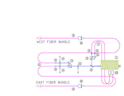
The light from the two fiber bundle beams is directed next to 2.5 cm diameter diffusers (8) (Thorlabs ED1-C20) with divergence angles that are located 20 mm in front of the input ends of the fiber bundles (9) and 20 mm from the end of the 550 micron fiber. The other two fibers couple to the reference PMTs (10).
A third solenoid (11) under computer control and located after the high transmissivity beam splitter, but before the lateral displacement prismatic beam splitter, allows a neutral density filter to be inserted into the undeflected beam to be able to balance the amount of light going to the barrel and endcap TOF counters. Neutral density filters (11) are also placed in front of the reference PMTs to reduce the amount of light that they receive. Moveable stages are used at all key points in order to allow precise alignment of optical components.
6 TOF monitor control electronics
The laser monitoring system interfaces with the BES3 data monitoring program and the data acquisition (DAQ) system using a VME TOF monitor control module, as shown in Fig. 9. This module enables the laser interlock, sends trigger pulses to the laser driver, controls the three solenoids, and digitizes the time and charge of the pulses from the two reference PMTs using the same HPTDC readout scheme as is used for the TOF counter PMTs. The desired number of triggers, trigger rate, and solenoid status are under the control of the TOF monitoring program. After each laser pulse, the VME module sends a monitor level 1 trigger to the fast readout control.
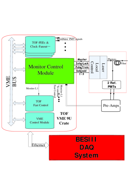
A second control interface was designed to allow manual operation of the laser monitor system in “stand alone” mode. It has toggle switches to control the solenoids, the laser interlock, and to send trigger pulses to the laser driver, as well as potentiometers to adjust the reference PMT control voltages. This system also acts, when set to “remote mode”, as an interface between the TOF monitor control electronics and the laser box components. In either mode, it supplies the actual power to the solenoids, the interlock enable voltage, the trigger pulses, and the necessary voltages for the reference PMTs. The heart of the second control interface is a ML403 Xilinx board that houses a Virtex 4 FPGA.
7 Optical fiber bundle tests
Before installation, the fiber bundles were tested for light transmission uniformity and length uniformity. The test setup is shown in Fig. 10. The PicoQuant laser diode head operating at 1 kHz illuminates the common end of a fiber bundle through a diffuser that provides nearly uniform illumination at the input end. One fiber is chosen as the reference, and the differences between the arrival times of the laser pulses from the reference fiber and all other fibers are determined. The measurements are made with the two Hamamatsu R7400U reference PMTs, and the pulse times and charges are measured with a V1290A, 32 channel, 25 ps CAEN TDC and a V965A, 8 channel dual range, CAEN QDC.
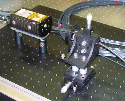
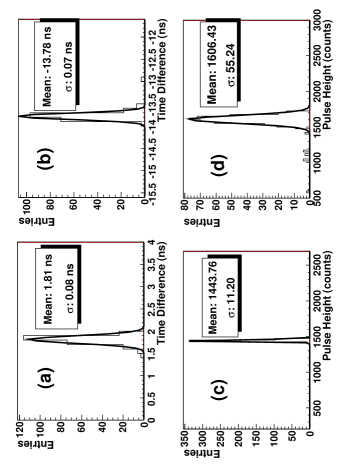
Fig. 11 shows the time differences with the reference fiber for (a) barrel fibers and (b) endcap fibers. Important here is the resolution, which is ps for the barrel fibers and ps for the endcap fibers. These include the read out resolution plus contributions due to the variation of the fiber’s lengths. Assuming the length variation is dominant, the 67 ps time resolution for the endcap corresponds to a length variation of cm. Figure 11 (c) and Fig 11 (d) show the charge distributions of the reference PMT and all other PMTs, respectively. The resolution of the reference PMT is 0.8%, which includes the resolution of the charge readout plus the variation of the laser diode intensity and demonstrates the great stability of this device. The charge resolution of all other fibers is 4.0%, which has contributions from the charge readout and the pulse-to-pulse variation of the laser diode intensity, as well as the uniformity of the laser beam over the input end of the laser bundle and the transmission uniformity of the fibers.
8 Laser bundle illumination uniformity
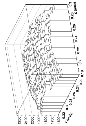
The illumination uniformity at the input end of the fiber bundle was measured by scanning a single fiber both horizontally and vertically across the light beam exiting from one of the diffusers in the laser box, shown in Fig. 8. The result is shown in Fig. 12. The percentage RMS variation over a region of 3.0 mm x 3.0 mm is 3.1%. This contributes a large component to the charge resolution of 4% that was measured for all other fibers in Fig. 11 (d).
9 Performance
Here results of the TOF monitoring system, readout using the full DAQ system, are shown after installation in the BES3 detector. The system generates 10,000 laser pulses at a 1 kHz repetition rate to either the west end or east end of the BES3 detector. Shown in Fig. 13 (a) is the Q distribution for reference PMT 1; the resolution is about 18 counts or 1.5%. Shown in Fig. 13 (b) is the time difference between the two reference PMTs; the resolution is 8.7 counts or about 26 ps, which is consistent with the expected resolution of the TOF readout system using HPTDC chips.
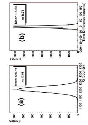
Figure 14 shows distributions for a typical TOF PMT of Q and the time difference with a reference PMT after the “time-walk” correction. The Q resolution is about 77 counts or 4.2%, and the time resolution is 22 counts or about 66 ps. The “time-walk” correction accounts for the dependence of the measured time on the measured charge of the pulse. The correction is of the form:
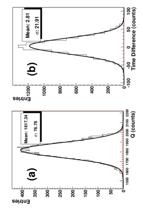
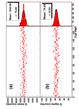
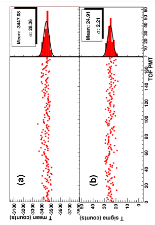
Figure 15 shows the mean and sigma of Q for all west barrel PMTs versus the PMT number. This plot is before fine adjustment of PMT high voltages. Figure 16 shows the mean and sigma of the time differences with a reference PMT for all west barrel PMTs.
10 Summary
Initial tests show that the TOF monitoring system using a PicoQuant laser diode and custom built fiber optic bundles is very successful. The resolutions obtained with R7400U reference PMTs are 1.5% for Q and about 24 ps for the time difference of the two PMTs. For a typical barrel counter PMT after the time-walk correction, the resolutions are 4.2% and 66 ps, respectively. This system will be used to test the TOF PMTs and electronics on a daily basis and check the performance of each PMT against historical values saved in a database.
11 Acknowledgements
We wish to thank all of our BES3 collaborators who helped make this work possible. We also want to thank Hiromichi Kichimi for much guidance in the design of this system, and Weiguo Li for useful suggestions on this paper. This work is supported by the BEPCII project, the CAS Knowledge Innovation Programs U-602, U-34 (IHEP), the National Natural Science Foundation of China (10405023), and the U.S. Department of Energy under Contract No. DE-FG02-04ER41291 (U. Hawaii).
References
- [1] J. Z. Bai et al., BES Collab., Nucl. Instrum. Meth. A344, 319 (1994).
- [2] J. Z. Bai et al., BES Collab., Nucl. Instrum. Meth. A458, 627 (2001).
- [3] F. A. Harris, BES Collab., Nucl. Phys. Proc. Suppl. 162, 345; physics/0606059 (2006).
- [4] Weiguo Li, BES Collab., Proceedings of the 4th Flavor Physics and CP Violation Conference (FPCP 2006), Vancouver, British Columbia, Canada, physics/0605158 (2006).
- [5] Y. Wang, BES Collab., Int. J. Mod. Phys. A21, 5371 (2006).
- [6] Chong Wu et al., Nucl. Instrum.& Meth. A 555, 142 (2005).
- [7] T. Kishida et al., Nucl. Instrum.& Meth. A 254, 367 (1987).