Study of the branching instability using a phase field model of inplane crack propagation
Abstract
In this study, the phase field model of crack propagation is used to study the dynamic branching instability in the case of inplane loading in two dimensions. Simulation results are in good agreement with theoretical predictions and experimental findings. Namely, the critical speed at which the instability starts is about . They also show that a full 3D approach is needed to fully understand the branching instability. The finite interface effects are found to be neglectable in the large system size limit even though they are stronger than the one expected from a simple one dimensional calculation.
pacs:
62.20.mmpacs:
46.15.-xpacs:
62.20.mt1 Introduction
The study of crack propagation has gained a lot of interest in the physical community during the recent years[1]. Among the many reasons that have driven this interest is the difficulty to understand the mechanism leading to the branching instability[2, 3] that prevents a crack from reaching its theoretical limiting speed: the Rayleigh wavespeed. During the branching instability, a single straight propagating crack separates into two sub cracks. While, the instability takes place in the process zone (the microscopic region ahead of the crack tip where the interatomic bond breaking leading to the crack propagation occurs), its effects (namely the propagation of two sub cracks) are macroscopic.
Hence a full description of the branching instability needs to describe both the macroscopic and the microscopic scales. The classical theory of crack propagation, describes well the macroscopic scale where the linear elasticity theory is valid but describes the crack propagation with laws that postulate the evolution of the crack path is a function of the stress intensity factors (number describing the singularity at the crack tip, that correspond to the three modes of crack propagation (see fig. 1). Such laws that do not describe in any way the small scale of the process zone can not account for the onset of the branching instability unless one explicitly provides a criteria that determines when a crack divides into two sub-cracks. Yet, they provide useful results such as necessary conditions for branching[4, 5].
On the opposite, the use of molecular dynamics simulations can help understanding the way a crack propagates and eventually divides into branches,since it allows to compute what happens at the microscopic scale.[6] Nonetheless, it does not allow to reach neither long enough time scales nor large enough space scales to fully simulate multiscale problems.
Therefore, in order to describe crack propagation an alternative approach may be to use phenomenological models of crack propagation. Such models aim at describing the behavior of the elastic material in the process zone with the use of non-linear elasticity. Typically, these models describe the process zone as a region where the material softens gradually from a fully intact state where the law of elasticity are verified to a fully broken state where the crack cannot transmit any stress.
A pioneering work was the introduction of the cohesive zone model where the crack line is prolongated by a softening segment[7, 8]. More recently using idea from the phase transition theory, phase-field models of crack propagation were introduced[9, 10, 11, 12, 13, 14, 15, 16] to describe crack propagation. They have already proved they can well describe the complex crack path in many cases[10, 17]. In addition such models have been able to reproduce the feature of the crack branching in the case of mode III cracks[18, 12]. Here, a study of the branching instability using the phase-field model is presented in the case of the inplane crack propagation (mode I and II). It must be emphasized here that while previous works have been devoted to the case of mode III crack propagation (paper tearing mode), this works is devoted to mode I crack propagation (pure tensile loading) which corresponds to usual experimental setups. The convergence of the numerical results is discussed and a comparison with available experimental data is presented. Results show that the phase field approach is in good quantitative agreement with both theoretical predictions[5] and experimental results, they also show that in order to fully understand three dimensional crack branching, three dimensional simulations are needed.

2 model and numerical implementation
The model used here has been introduced in the case of antiplane loading in[9] It has been shown to reproduce well the branching instability of cracks under antiplane loading[18]. The extension of the model to crack propagation under inplane loading was presented in [10] where it was shown to reproduce well the oscillating instability of cracks under bi-axial strain and also some feature of the branching instability. This later model was designed to comply with the principle of local symmetry and it has recently been used in the study of quasistatic crack propagation under thermal load.[16]
The principle of the phase field approach is to introduce an additional continuously (in space and time) varying variable that will describe the state of the elastic material (e.g. : broken and :intact). It will evolve obeying an evolution equation which couples with the elastic fields. The equations of motion of the elastic material are also coupled in an appropriate way with the phase field. In this framework, the crack surface can be seen as an isocontour of the phase field (e.g. ). Since is varying continuously, the singularity at the crack tip is smeared out and the sharp tip is replaced by a smooth region where is varying rapidly from 1 to 0. This region may be considered as the process zone where failure occurs. This approach differs from the cohesive zone approach[7, 8] because instead of smoothing the singularity by prolongating the crack line by a soft interface line directed along the predicted a priori path of the crack, it smooths the singularity at the crack tip by introducing a soft region. In this approach the crack faces are no longer lines but regions where the elastic moduli of the material go from their nominal values to zero and there is no need to know a priori the crack path.
First the model is described in more details. The equation for the displacement fields ( where ) writes as in[10]:
| (1) | |||||
| (2) |
where is the strain tensor and is, in the limit of linear elasticity, equal to . The function couples the phase field with the displacement fields and it has been chosen so that the stress transmitted through a crack vanishes in the large system limit (i.e. when the size of the system becomes much larger than the width of the crack interface introduced by the phase field.)[9]. The equation for the phase field writes:
| (3) | |||||
| (4) | |||||
| (7) |
Equation (3) insures that the phase field will not increase, which means that a crack can not heal. Equations (7, 4), are similar to the free energy used in [9]. The form of the coupling term in (eq. 4), indicates (if one neglects curvature effects at the tip) that the crack will propagate in a region where the value of is higher than . Contrarily to the model of [9], here is not the local energy density. It takes into account the fact that the material is either under compression (, is the contribution of shear to the local elastic energy density) or extension (, is the local elastic energy density) and that a crack should not propagate in a material under compression. Therefore equations (7, 4) impose that in a material under compression, the favored state is intact material ()
This model depending on the imposed boundary conditions can describe the propagation of a crack (or of many cracks) under arbitrary loading conditions. Model parameters used here are , , and . The fracture energy in the large system[9, 10] limit is:
| (8) |
Here we have applied this model to the study of a dynamic crack propagating under mode I (tensile) loading: the top and bottom boundaries of the sheet are moved of and . Parameters are so that the thickness of a crack () at the onset is approximately 1 s.u.( was also used without any significant change), , , which implies that the shear wave speed is and the Rayleigh wave speed is . The system is prepared at mechanical equilibrium with an initial pre-crack. Then the equations (1,3) are simulated on a regular grid (with grid spacing ) using a forward Euler scheme. The discretization scheme is chosen to keep the mechanical energy constant (if the phase field is kept constant and so that the total energy decreases when the phase field evolves.). In addition, checks were performed to insure that discretization effects are neglectable: dividing the grid spacing by 2 did not affect results by more than 1 percent.
Since the focus of this study is the stability/instability of straight cracks propagating at constant speed, simulations were performed on a grid moving with the crack tip in order to let the transient accelerating regime disappear. The simulation grid had an aspect ratio () of 1. Simulations using larger and smaller aspect ratios (0.5, 2 and 4) showed a small change in quantitative results: namely an approximately drop of the branching speed of 2 percents in the infinite aspect ratio limit for the three smallest width (12.5 25 and 50 and 100) and . On the contrary, changing the ratio , where is the interface thickness of the crack, did affect quantitatively the results. But, as expected[9], results converge towards a limit when the size of the sample , compared to the width of the crack , goes to infinity (keeping the elastic energy stored in the uncracked medium () per unit length and other parameter constant). Therefore the fact that results are affected when changing does not indicate that the branching is size dependent. It is indicative of the effects of the finite width of the crack in the phase field model (It is not due to the fact that the full stress relief only occurs in the infinite limit, which is a 1D effect. It is due to the fact that a finite distance exists between the edges of the crack).
3 Straight crack


First some results on the propagation of a stably propagating single crack are presented. Using the model parameters, the fracture energy is . According to the Griffith criterion, one expects that a crack will begin to propagate when the elastic energy stored per unit length is larger than the energy needed to create two crack interfaces, that is for . Simulations results show that this prediction is extremely well verified, with an error smaller than a percent, for the smallest simulation boxes used here (W=25). For bigger systems (W=50, 100 and 200), the error is always at most of the same order of magnitude. Hence the model used here is in very good agreement with the Griffith criterion.
When the value of is increased, the speed of the straight crack is expected to obey the law:
| (9) |
where is the mechanical energy that is either disspated or converted into surface energy when the fracture advances of one space unit at speed , G is the mechanical energy available far ahead from the crack tip and is a universal function that depends solely on the elastic properties of the material (for further details see ref.[19] sections 5.3 and 5.4). Simulation results using the phase field model and eq. 9 show that
| (10) |
with a constant, for values of below the branching threshold, and indicate that for , the fracture energy is independant of the crack speed (zero dissipation limit). It must be noted here that for or a given model parameter set, the relation between the steady crack speed and the available mechanical energy ahead of the crack tip is independant of the system size (see fig. 2).
At this point, before turning to the study of branching instability, it is worth to summarize the results obtained here. First the phase field model, as already shown in [10] obeys the Griffith criterion. In addition, the relation between the model parameter and the speed dependance of the fracture energy has been computed (eq.10). The later result together with theoretical prediction in [5] which show that the branchinsg speed behaves like , allows to predict that the branching speed in the phase field model must behave linearly with (taking into account the fact that in [5], only a necessary condition for branching was derived while here we focus on the onset of branching).
We now turn to the main purpose of this work: the study of the branching instability.
4 branching instability


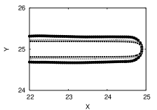
When the value of is further increased, the crack tip becomes unstable and the crack divides into two cracks. As shown in [18], this instability occurs through tip blunting. As the crack speed increases, the radius of curvature of the crack tip increases and when the speed is larger than a critical value, the crack tip splits into two branches that propagate (see fig. 3, where one can see that the crack tip is still much smaller than the system width). One of those two branches can be faster than the other and through screening of stress eventually prevents the propagation of the other branch. Then if strain is sufficient, the scenario repeats and one can see a succession of branching events giving birth to two cracks, the selection of one of them its acceleration and separation into two cracks… This regime of sustained disordered branching events can only take place if strain is sufficient and corresponds to the macro-branching instability (see fig. 3). Its signature when considering the crack surface is the presence of successive branches of various sizes. In addition to this qualitative description, one notices a sharp increase in the variance of the crack speed which is similar to the one observed in experiments despite some discrepancies (The variance of the crack speed as a function of the mean crack speed increases via a discontinuous jump in 2D simulations while in experiment it increases linearly above threshold) which could be attributed to the 3D nature of experiments. This transition is easily noticed when considering the velocity profile (Here crack velocity is the time derivative of the position of the most advanced point of the crack: the iso contour ). Instead of small oscillations one can see sharp decreases of the crack speed followed by a progressive acceleration of the crack and again a sharp decrease (see fig. 4). This behavior of the crack speed is typical of a branching event and is in good agreement with the scenario presented in [5], with numerical observations of [18] and with experimental results.

The critical speed depends on the model parameters (here: 111Additional simulations have shown that dividing by 10 did not affect results and simulations of[18] in the case of mode III cracks show that is the correct limit in the sense that it allows to retrieve theoretical predictions) and on the system size (see fig. 5). While the dependence on is expected since measures the energy dissipation at the crack tip, the dependence on is not the result of any physical phenomena and comes from the way the phase field models deals with the singularity at the crack tip.
Indeed, it does not allow to consider an infinitely sharp crack. It only allows to reproduce a crack of finite width and one should retrieve the results of an infinitely sharp crack in the limit . Simulations results show that this is actually the case. In the limit , the value of the critical speed at which the macroscopic branching instability occurs for a given value of converges toward a finite limit while the qualitative behavior of the system remains unchanged. As mentioned earlier, this limit is a function of which measures the dissipation in the material. As a result, in the limit , the phase field model reproduces the behavior of a perfectly brittle material. Simulations using different values of show that the branching speed scales linearly with and converges toward a finite value when as one would expect from [5] and the results of the study of steady crack propagation.
Then in the limit , one gets the value of a critical macroscopic branching speed for a perfectly brittle material without any dissipation of approximately 0.48. This value is in fairly good agreement (a discrepancy) with theoretical results of[5] which predicts a branching speed of 0.42 (with parameters used here). The discrepancy can be easily attributed to the fact that in [5], the critical speed that was computed, was the speed at which branching can occur, i.e. a necessary condition, while here the computed speed is the one at which a straight crack is no longer stable. And to reinforce this, it is important to mention that during simulations branching events were observed at instantaneous speeds lower than the the measured critical velocity.


When comparing, the results obtained here with the experiments[20, 21, 22], one must first note that the three dimensional character of the branching instability cannot be reproduced by our simulations and that in PMMA, according to [22] (figs. 19 and 17), the branching instability can be described as 2 dimensional for average crack speeds much higher () than the critical speed for the 3D branching instability (). In addition, dissipative effects are present in PMMA and are not well quantified above the first critical speed (). Then, it is clear that our simulations can not be compared quantitatively with the experimental results. Nonetheless, some qualitative comparison are possible. First of all, the computed branching angle defined as the angle between the secondary crack and the main direction of propagation of the crack is in good agreement with experimental results. It is on average equal to (with some visible variations), which is close to the experimental value of . Interestingly enough, if one defines the branching angle as the angle between the two branches the computed values is then around which is in rather good agreement with theoretical predictions of [4, 5]. The discrepancy in the computed values of angles may come from the fact that the phase field method does not allow to compute the branching angle at the onset of the branches leading to a small under-estimation of its value. Indeed, the branching point is defined up to a few interface thicknesses and the behavior of the branches can only be described a few interface thicknesses away from the branching point. These shortcomings of the phase field approach do not allow to check the asymptotic behavior of branches close to the onset of branching. Simulations in larger systems are needed to overcome the finite interface limitation.

From a statistical point of view, the crack speed fluctuations power spectrum in the case where no dissipation occur in the bulk did not exhibit any clear frequency. The same behavior was observed in the case where a small dissipation was added in the bulk. Nonetheless, during the repetitive branching burst, the frequency of branching events was found to be fairly constant for given model parameter values. Namely its Independence on the system size, on the crack speed could not be determined. Nonetheless, a clear dependence on the value of was found: the inter-branch interval is approximately proportional to as can be observed in fig. 6. This behavior is true for small frequencies (i.e. for ). But for small values of (lower than 2), one can see that the inter-branch intervals ceases to decrease and saturate at a given value. This saturation may be attributed to the finite thickness of the interface (there exists a minimal interbranch distance which can be estimated to be equal to a few interfaces thicknesses. Here, assuming a crack speed of around , and considering the crack width of 1. su., the highest frequency should be a fraction of 0.5.222It cannot be more than 0.5 and it is reasonable to assume that one needs at least a few crack width between branches.).Hence as is decreased, phase field simulations show an increase of the typical frequency until it reaches the saturation frequency.
5 Discussion
Results of simulations presented here show that the phase field approach is useful to understand fracture as a pattern formation mechanism. Nonetheless, the fact that crack propagation is due to the singularity at its tip, finite size effects due to the phase field approach turn out to be much stronger than one would expect from the 1D calculation of [9]. This slow convergence does not prevent the model to retrieve quantitatively good results in the large system size and the use of better simulation methods (such as Finite elements or adaptive remeshing) should allow to consider systems where finite size effects are neglectable. Hence, the phase field model is able the reproduce correctly the branching instability in the case of 2D crack propagation, predicting a critical speed of , which is larger than the necessary condition derived in [5]. Since the branching instability is essentially a 3D process[22], comparison with experiments is only indicating that the phase field model can reproduce the main features of the branching instability. But results and comparison with experiments indicate that full 3D simulations are needed to be able to understand the branching instability. One of the expected results of this is to be able to understand what are the parameter that govern the formation of fracture patterns such as the parabolic markings shown in [22].
Acknowledgements.
I wish to thank Mokhtar Adda-Bedia, Alain Karma, Eran Sharon and Jay Fineberg for fruitful discussions during this work.References
- [1] \NameFineberg J. Marder M. \REVIEWPhys. Rep. 31319992.
- [2] \NameFineberg J., Gross S. P., Marder M. Swinney H. L. \REVIEWPhys. Rev. Lett. 671991457.
- [3] \NameRavi-Chandar K. Knauss W. G. \REVIEWInt. J. Fracture 251984247.
- [4] \NameAdda-Bedia M. \REVIEWJ. Mech. Phys. Solids 532005227.
- [5] \NameKatzav E., Adda-Bedia M. Arias R. \REVIEWInternational Journal of Fracture 1432007245.
- [6] \NameMarder M. \REVIEWInt. J. frac. 1302004517.
- [7] \NameBarenblatt G. \REVIEWAdvances in Applied Mechanics 7196255.
- [8] \NameDugdale D. \REVIEWJournal of the Mechanics and Physics of Solids 81960100.
- [9] \NameKarma A., Kessler D. Levine H. \REVIEWPhys. Rev. Lett. 872001045501.
- [10] \NameHenry H. Levine H. \REVIEWPhysical Review Letters 932004105504.
- [11] \NameEastgate L., Sethna J., Rauscher M., Cretegny T., Chen C.-S. Myers C. \REVIEWPhys. Rev. E 65200236117.
- [12] \NameAranson I. S., Kalatsky V. A. Vonokur V. M. \REVIEWPhys. Rev. Lett. 852000118.
- [13] \NameSpatschek R., Hartmann M., Brener E., Muller-Krumbhaar H. Kassner K. \REVIEWPhysical Review Letters 962006015502.
- [14] \NamePilipenko D., Spatschek R., Brener E. A. Muller-Krumbhaar H. \REVIEWPhysical Review Letters 982007015503.
- [15] \NameBrener E. A. Spatschek R. \REVIEWPhys. Rev. E 672003016112.
- [16] \NameCorson F., henry H., Katzav E. Adda-Bedia M. \BookThermal fracture as a framework for a crack propagation law preprint arXiv:0801.2101.
- [17] \NameHakim V. Karma A. \REVIEWPhysical Review Letters 952005235501.
- [18] \NameKarma A. Lobkovsky A. E. \REVIEWPhys. Rev. Lett. 922004245510.
- [19] \NameFreund L. \BookDynamic Fracture Mechanics (Cambridge University Press (UK)) 1990.
- [20] \NameSharon E., Gross S. P. Fineberg J. \REVIEWPhys. Rev. Lett. 7419955096.
- [21] \NameSharon E., Gross S. P. Fineberg J. \REVIEWPhys. Rev. Lett. 7619962117.
- [22] \NameSharon E. Fineberg J. \REVIEWPhys. Rev. B 5419967128.