High Resolution Imaging of Single Atoms in a Quantum Gas
Our knowledge on ultracold quantum gases is strongly influenced by our ability to probe these objects andrews1996 ; schellekens2005 ; oettl2005 ; foelling2005 . In situ imaging combined with single atom sensitivity is an especially appealing scenario as it can provide direct information on the structure and the correlations of such systems naraschewski1999 ; kheruntsyan2005 ; sykes2008 . For a precise characterization a high spatial resolution is mandatory. In particular, the perspective to study quantum gases in optical lattices greiner2002 ; mandel2003 ; bloch2008 makes a resolution well below one micrometer highly desirable. Here, we report on a novel microscopy technique which is based on scanning electron microscopy and allows for the detection of single atoms inside a quantum gas with a spatial resolution of better than 150 nm. Imaging a Bose-Einstein condensate in a one-dimensional optical lattice with 600 nm period we demonstrate single site addressability in a sub-m optical lattice. The technique offers exciting possibilities for the preparation, manipulation and analysis of quantum gases.
Ultracold atoms can be visualized by various techniques. Absorption imaging ketterle1999 is the workhorse in most experiments and is typically applied in time of flight in order to increase the cloud size and reduce the optical density. While phase contrast imaging andrews1996 ; shin2006 is well suited for trapped quantum gases, fluorescence imaging hu1994 ; schlosser2001 ; teper2006 ; kuhr2001 ; schrader2004 ; nelson2007 is especially attractive as it allows for single atom detection with almost 100% efficiency. It has been applied to isolated thermal atoms at low densities but has not yet been extended to single atom detection in quantum gases. The best achievable resolution of these optical techniques is ultimately limited by half the wavelength of the used light field - in practice, the best reported resolution is about 1 m schlosser2001 . Direct particle detection of metastable atoms in time of flight schellekens2005 ; jeltes2007 and outcoupling of single atoms from a condensate with a radio frequency field oettl2005 are alternative techniques which have been developed. However, they either cannot be applied to trapped samples schellekens2005 ; jeltes2007 or are restricted to one spatial dimension oettl2005 . Whereas each of those techniques has its specific advantages and applications, a versatile in situ detection of single atoms in a quantum gas is lacking. Moreover, a spatial resolution of below 1 m which opens the intriguing perspective to resolve single sites in a sub-m optical lattice has not yet been achieved.
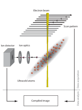
In our experiment we have transferred the principles of scanning electron microscopy to the detection of ultracold atoms (Fig. 1). A focused electron beam with keV electron energy, a full width half maximum (FWHM) diameter of 100-150 nm and a current of 10-20 nA is scanned across a Bose-Einstein condensate of rubidium atoms which is prepared in an optical dipole trap gericke2007 . The atoms are ionized by electron impact ionization, extracted with an electrostatic field and subsequently detected by an ion detector. The small diameter of the electron beam ensures a high spatial resolution, whereas the ion detection provides single atom sensitivity. The total ionization cross section at keV electron energy for rubidium is bartlett2004 and represents 40% of all scattering events schappe1995 ; schappe1996 . Elastic and inelastic electron-atom collisions constitute the remaining events and lead to atom loss with no detectable signal. As the cross section is eight orders of magnitude smaller compared to the absorption cross section of a resonant photon, the atomic cloud is optically thin for the electron beam. For typical parameters, only 1 out of 500,000 incident electrons undergoes a collision.
When exposed to the electron beam, the probability for the detection of an atom at a position is given by (see Methods section)
| (1) |
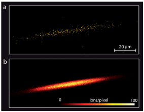
Here, is the electron beam current, is the electron charge, is the pixel dwell time of the electron beam, is the detector efficiency, denotes the column density of the atom’s wave function along the propagation direction of the electron beam (z-direction) and is the number of atoms in the single particle state. In Fig. 2a we show a scanning electron microscope image of a Bose-Einstein condensate. For our experimental parameters, a fraction of 350 atoms is detected (the total number of atoms in the condensate is about 100,000). In a Bose-Einstein condensate all atoms occupy the same quantum state and the many-body wave function separates into the product of identical single particle wave functions , with being the number of atoms in the condensate. Therefore, the interpretation of the image involves quantum-mechanical concepts: As the single particle wave function extends over the whole atomic cloud, the spatially resolved detection of an atom must be understood as a projective measurement in position space. As a consequence, the retrieved image is intrinsically probabilistic. This is in contrast to almost all microscopy images showing the distribution of individual atoms as in these cases the location of the atoms is already fixed prior to their detection. Another important aspect is related to the Heisenberg uncertainty principle. During the detection process, the atom is coupled to a probe (in our case an electron beam) and energy as well as momentum can be exchanged between them. Consequently, the localization of an atom within a range enforces a momentum spread of . If is smaller than the extension of the wave function , substantial momentum transfer is unavoidable and the detected atom is no longer part of the condensate, regardless of the specific experimental realization. Hence, the ionization of the atoms in our scheme does not constitute a serious limitation or drawback. It is even advantageous because it helps rapidly extracting the reaction products from the remaining system, keeping possible perturbations small.
Whether the image in Fig. 2a is indeed a probabilistic selection of the full atomic distribution according to equation (1), can be checked by summing over many images (Fig. 2b) and comparing them to a theoretical density profile. The profile is derived from the so-called semi-ideal model minguzzi1997 ; naraschewski1998 ; gerbier2004 , which describes a bimodal distribution at finite temperature. While the condensate part is obtained from a numerical solution of the 3D-Gross-Pitaevskii equation, the thermal component is modelled as a non-interacting gas in an effective potential, taking into account the repulsion of the thermal atoms by the condensed atoms (see Methods section). The comparison with our data (Fig. 3a,b) exhibits very good agreement over the whole extension of the cloud including the wings of thermal atoms. This gives not only indirect evidence of the repulsion between the condensate fraction and the thermal component in the trap (Fig. 3c), but also confirms that the image shown in Fig. 2a displays a probabilistic selection of atoms.
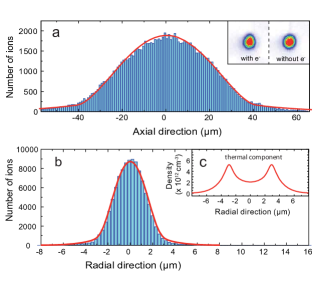
Comparing the condensate with and without exposure to the electron beam (absorption images in the inset of Fig. 3a) we do not find any significant difference apart from a reduction in atom number by about 7%. These losses are composed of two contributions: primary electron atom collisions and secondary collisions of the primary reaction products. We find that every scattered atom or produced ion kicks off on average one more atom. In all these collisions the energy transfer is much larger than the depth of the optical potential and all scattered particles can escape from the trap. Essentially no energy is deposited in the cloud as we observe an additional heating of merely 5 nK after exposure to the electron beam. Thus, the perturbation caused by the detection process is very small. If not, the scanning speed could be made larger than the speed of sound in the condensate providing an effectively unperturbed cloud during the whole imaging sequence. According to equation (1), high imaging speed is associated with a reduced signal and a convenient setting of the imaging parameters has to be chosen for each application. Most detected ions are singly charged (80%) but we also find higher charged states of up to resulting from inner shell ionization. Only out of detected events is due to background gas ionization or dark counts which results in a high signal to noise ratio as evidenced by Fig. 2. Taking into account a detector efficiency of 30% the total efficiency for our detection scheme is currently limited to 12%. It can be increased by a more efficient ion detector and additional photoionization of inelastically scattered atoms. We estimate that a total detection efficiency of more than 50% could be feasible.
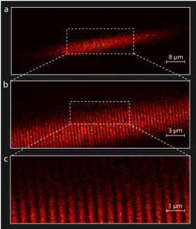
In order to characterize the resolution of our imaging technique we have loaded the condensate in a one-dimensional optical lattice with lattice period. A sequence of electron microscope images with increasing resolution is shown in Fig. 4a-c. The periodic structure of the potential is clearly resolved with high contrast. As a scanning probe technique is used for the image formation, the addressability of individual lattice sites is demonstrated as well. The atomic density in each lattice site is radially symmetric with a diameter of m and a thickness of and documents the large depth of focus of the electron optical imaging system.
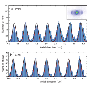
One of the most intriguing properties of a Bose-Einstein condensate is its macroscopic phase coherence. In a periodic potential the phase coherence can be easily verified by interference experiments. An absorption image of the condensate after a ballistic expansion of is shown in the inset of Fig. 5a. The image was taken after illumination with the electron beam and the appearance of the characteristic diffraction peaks demonstrates that the partial measurement of a subset of atoms does not destroy the coherence of the remaining system. Furthermore, it is an example for a complementary measurement in position and momentum space on a single many-body quantum system. For a quantitative analysis we compare the integrated linescans with the Bloch wave function that describes the ground state of non-interacting atoms in the lattice potential (Fig. 5a,b). The periodic structure and the shape of the individual on-site wave function are well reproduced for both data sets. Together with the observed interference pattern both, the density distribution and the quantum-mechanical phase are determined and thus, the Bloch wave function is fully characterized. Eventually, we conclude from the good agreement that our imaging technique achieves a spatial resolution of better than (see Methods section).
The combination of high spatial resolution and single atom sensitivity will open up new possibilities for the in situ study of spatial and temporal correlations in trapped quantum gasesnaraschewski1999 ; kheruntsyan2005 ; sykes2008 . Previous experimental work on correlations in trapped esteve2006 and expanding jeltes2007 ; foelling2005 ; greiner2005 gases has already demonstrated the high potential of such measurements. In optical lattice systems, the technique cannot only be used as a powerful characterization tool. Removing atoms from specific lattice sites, it also allows for the preparation of tailored quantum systems. Taking advantage of the electron beam’s magnetic field even a coherent manipulation of single atoms could be feasible.
Methods
Detection probability:
An atom that is located in the centre of a Gaussian electron beam with a radial current density of , has a lifetime against electron impact of . Here, is the current density in the beam centre, is the beam current, is the -width of the beam, is the electron charge, and cm2 is the total electron scattering cross section for rubidium at 6 keV electron energy. For typical beam parameters ( nA, nm, corresponding to nm) we obtain s. If the pixel dwell time is much smaller than , the probability for a scattering event (ionization, elastic or inelastic scattering) is given by
If the atom is described by a wave function and if we assume that the beam is much smaller than the extension of the wave function, the probability of a scattering event at the position is given by
| (2) |
Multiplying equation (2) with the ion production efficiency , the detector efficiency , and the total number of atoms gives equation (1) of the main text.
Bimodal distribution: For a given number of condensed atoms we numerically solve the Gross-Pitaevskii equation
| (3) |
using an imaginary time propagation algorithm. The external potential is cylindrically symmetric and has the form , where denotes the axial direction of the condensate, Hz ( Hz) is the axial (radial) oscillation frequency of the dipole trap, is the chemical potential, is the coupling constant, and is the rubidium mass. For the s-wave scattering length we use a value of , with being the Bohr radius. In our experiment we produce a spinor condensate in the ground state of rubidium. For the model presented here we neglect the spinor nature because the difference in the scattering lengths for the and scattering channels are only 1% vankempen2002 . The condensate wave function is normalized to the total number of condensed atoms, . The numerical solution of equation (3) is used to model an effective potential for the thermal component
The density distribution of the thermal component is then given by
| (4) |
with a modified fugacity
Here, is the thermal de-Broglie wavelength, is the Boltzmann constant and is the temperature. The number of atoms in the thermal component is given by and the total number of atoms is .
Spatial resolution: The size of the electron beam can be determined independently by scanning the beam across a sharp edge of a movable test target which is implemented in the vacuum chamber. We define the resolution as the distance between two neighbouring point-like scatterers where the signal intensity in between drops to 75%. This definition is the analogue to the Rayleigh criterion in optics and for our system translates into a resolution of , assuming a Gaussian beam profile. The electron beam used for the measurement in Fig. 4 and 5 of the main text has a diameter of 95 nm FWHM, corresponding to a resolution of 115 nm. The good agreement between the experimental line scan and the theoretical model in Fig. 5 proves that a similar resolution is achieved for the electron microscope images of ultracold atoms.
We would like to thank A. Widera and T. Best for valuable discussions and C. Utfeld for contributions in the early stage of the experiment. This work was funded through the DFG and the Forschungsfond of the University of Mainz.
References
- (1) M. Andrews et al., Science 273, 84 (1996).
- (2) M. Schellekens et al., Science 310, 648 (2005).
- (3) A. Öttl, S. Ritter, M. Köhl, and T. Esslinger, Phys. Rev. Lett. 95, 090404 (2005).
- (4) S. Fölling et al., Nature, 434, 481-484 (2005).
- (5) M. Naraschewski and R. J.M. Glauber, Phys. Rev. A 59, 4595 (1999).
- (6) K. Kheruntsyan, D. Gangardt, P. Drummond and G. V. Shlyapnikov, Phys. Rev. A 71, 053615 (2005).
- (7) A. G. Sykes et al. Phys. Rev. Lett. 100, 160406 (2008).
- (8) M. Greiner, O. Mandel, T. Esslinger, T. W. Hänsch, and I. Bloch, Nature 415, 39 (2002).
- (9) O. Mandel et al., Nature 425, 937 (2003).
- (10) I. Bloch, Science 319, 1202 (2008) and references therein.
- (11) W. Ketterle, D. Durfee, and D. Stamper-Kurn, in Bose-Einstein condensation in atomic gases, Proceedings of the International School of Physics ”Enrico Fermi” (IOS Press, Amsterdam, 1999).
- (12) Y. Shin, M. Zwierlein, C. Schunck, A. Schirotzek, and W. Ketterle, Phys. Rev. Lett. 97, 030401 (2006).
- (13) Z. Hu and H. Kimble, Opt. Lett. 19, 1888 (1994).
- (14) N. Schlosser, G. Reymond, I. Protsenko, and P. Grangier, Nature 411, 1024 (2001).
- (15) S. Kuhr et al., Science 293, 278 (2001).
- (16) I. Teper, Y. Lin, and V. Vuletic, Phys. Rev. Lett. 97, 023002 (2006).
- (17) D. Schrader et al., Phys. Rev. Lett. 93, 150501 (2004).
- (18) K. Nelson, X. Li, and D. Weiss, Nature Physics 3, 556 (2007).
- (19) T. Jeltes et al., Nature 445, 402 (2007).
- (20) T. Gericke, P. Würtz, D. Reitz, C. Utfeld, and H. Ott, Appl. Phys. B 89, 447 (2007).
- (21) P. L. Bartlett and A. T. Stelbovics, At. Data Nuc. Data Tab. 86, 235 (2004).
- (22) R. Schappe, P. Feng, L. Anderson, C. Lin, and T. Walker, Europhys. Lett. 29, 439 (1995).
- (23) R. Schappe, T. Walker, L. W. Anderson, and C. C. Lin, Phys. Rev. Lett. 76, 4328 (1996).
- (24) A. Minguzzi, S. Conti, and M. P. Tosi, J. Phys.:Condens. Matter 9, L33 (1997).
- (25) M. Naraschewski and D. M. Stamper-Kurn, Phys. Rev. A 58, 2423 (1998).
- (26) F. Gerbier et al., Phys. Rev. A 70, 013607 (2004).
- (27) J. Estève et al., Phys. Rev. Lett. 96, 130403 (2006).
- (28) M. Greiner, C. A. Regal, J. T. Stewart, and D. S. Jin, Phy. Rev. Lett. 94, 110401 (2005).
- (29) E. G. M. van Kempen, S. J. J. M. F. Kokkelmans, D. J. Heinzen, and B. J. Verhaar, Phys. Rev. Lett. 88, 093201 (2002).