∎
22email: francois.boulanger@ias.u-psud.fr
33institutetext: J. P. Maillard (Payload Scientist), H. Roussel 44institutetext: Institut d’Astrophysique de Paris, CNRS et Université P. & M. Curie, 98 bis Blvd Arago, 75014 Paris, France
44email: maillard@iap.fr
55institutetext: S. Cabrit, F. Combes, E. Falgarone, F. Viallefond (LERMA), J. Le Bourlot (LUTH) 66institutetext: Observatoire de Paris, 75014 Paris, France
77institutetext: P. Desmet, E. Gavila, B. Huet 88institutetext: Thales Alenia Space, 06322 Cannes La Bocca, France
99institutetext: A. Dutrey, S. Guilloteau 1010institutetext: Observatoire de Bordeaux, 33270 Floirac, France
1111institutetext: C. Joblin, E. Pointecouteau 1212institutetext: Centre d’Etudes Spatiales des Rayonnements, 31028 Toulouse, France
1313institutetext: J. M. Deharveng, R. Grangé, C. Gry, L. Tresse 1414institutetext: Laboratoire d’Astrophysique de Marseille, 13376 Marseille, France
1515institutetext: S. C. Madden, C. Martin 1616institutetext: Service d’Astrophysique, Bât. 609, Orme des Merisers, CEA Saclay, 91191 Gif-sur-Yvette, France
1717institutetext: F. Bertoldi, J. Jorgensen 1818institutetext: Argelander Institute for Astronomy, University of Bonn, Auf dem Hügel 71, 53121 Bonn, Germany
1919institutetext: J. Bouwman, A. Carmona, O. Krause, T. Henning 2020institutetext: Max-Planck-Institut für Astronomie, Königstuhl 17, 69117 Heidelberg, Germany
2121institutetext: V. Charmandaris 2222institutetext: University of Crete, Department of Physics, P.O. Box 2208, 71003 Heraklion, Greece
2323institutetext: A. Bressan, A. Baruffalo, C. Bonoli, F. Borletto, G. L. Granato, R. Rampazzo, G. de Zotti, 2424institutetext: INAF-Osservatorio Astronomico di Padova, Vicolo dell’Osservatorio 5, 35122 Padova, Italy
2525institutetext: L. Danese 2626institutetext: Scuola Int. Sup. di Studi Avanzati (SISSA), Via Beirut 4, 34014 Trieste, Italy
2727institutetext: C. Pernechele 2828institutetext: INAF-Osservatorio Astronomico di Cagliari, Poggio dei Pini Strada 54, 09012 Capoterra (CA), Italy
2929institutetext: L. Silva 3030institutetext: INAF-Osservatorio Astronomico di Trieste, Via Tiepolo 11, 34143 Trieste, Italy
3131institutetext: J. Cernicharo, J. Pardo 3232institutetext: Dep. de Astrofis. Mol. e Infrarroja, Inst. de Estructura de la Materia, CSIC, Serrano 121, 28006 Madrid, Spain
3333institutetext: E. A. Valentjin, M. Spaans, F. F. S. van der Tak, W. Wild 3434institutetext: Netherlands Institute for Space Research (SRON), Groningen, The Netherlands
3535institutetext: M. J. Ferlet, T. L. Lim, B. Swinyard 3636institutetext: Rutherford Appleton Laboratory, Chilton, Didcot OX11 0QX, United Kingdom
3737institutetext: S. K. Ramsay Howat, G. S. Wright 3838institutetext: UK Astronomy Technology Center, Royal Observatory, Edinburgh EH9 3HJ, United Kingdom
3939institutetext: M. D. Smith 4040institutetext: Centre for Astrophys. and Planet. Science, School of Physical Sciences, The University of Kent, Canterbury CT2 7NH, United Kingdom
4141institutetext: L. Drissen, G. Joncas, 4242institutetext: Département de Physique, de Génie Physique et d’Optique and Observatoire du mont Mégantic, Université Laval, Québec, QC G1K 7P4, Canada
4343institutetext: P. G. Martin 4444institutetext: Canadian Institute for Theoretical Astrophysics, 60 St-George st, Toronto, Ontario, M5S 3H8, Canada
4545institutetext: P. Appleton, G. Helou, P. Ogle, B. Schulz 4646institutetext: IPAC, Cal. Institute of Technology, Mail Code 100-22, 770 South Wilson Avenue, Pasadena, CA 91125, USA
4747institutetext: C. J. Davis 4848institutetext: Joint Astronomy Centre, Hilo, HI 96720, USA
4949institutetext: B. T. Draine 5050institutetext: Princeton University Observatory, Princeton, NJ 08544, USA
5151institutetext: P. F. Goldsmith, A. K. Mainzer 5252institutetext: Jet Propulsion Laboratory, 4800 Oak Grove Drive, Pasadena, CA 91109, USA
5353institutetext: S.A. Rinehart 5454institutetext: NASA Goddard Space Flight Center, Greenbelt, MD 20771, USA
5555institutetext: A. G. G. M. Tielens 5656institutetext: NASA Ames Research Center, Moffett Field, CA 94035, USA
5757institutetext: G. J. Stacey 5858institutetext: Department of Astronomy, Cornell University, Ithaca, NY 14853, USA
5959institutetext: B. P. Wakker 6060institutetext: Department of Astronomy, University of Wisconsin, Madison, WI 53706, USA
The Molecular Hydrogen Explorer H2EX
Abstract
The Molecular Hydrogen Explorer, , was proposed in
response to the ESA 2015 - 2025 Cosmic Vision Call as a medium class space
mission with NASA and CSA participations. The mission, conceived to
understand the formation of galaxies, stars and planets from molecular
hydrogen, is designed to observe the first rotational lines of the
H2 molecule (28.2, 17.0, 12.3 and 9.7 m) over a wide field, and
at high spectral resolution. can provide an inventory of warm
( 100 K) molecular gas in a broad variety of objects, including
nearby young star clusters, galactic molecular clouds,
active galactic nuclei, local and distant galaxies. The rich array of
molecular, atomic and ionic lines, as well as solid state features
available in the 8 to 29 m spectral range brings additional
science dimensions to .
We present the optical and mechanical
design of the payload based on an innovative Imaging Fourier Transform
Spectrometer (IFTS) fed by a 1.2 m telescope. The 20’20’ field of view is imaged on two 10241024 Si:As detectors. The
maximum resolution of 0.032 cm-1 (FWHM) means a velocity
resolution of 10 km s-1 for the 0 – 0 S(3) line at
9.7 m. This instrument offers the large field of view necessary to
survey extended emission in the Galaxy and local Universe galaxies as
well as to perform unbiased extragalactic and circumstellar disks
surveys. The high spectral resolution makes uniquely suited to
study the dynamics of H2 in all these environments. The mission plan
is made of seven wide-field spectro-imaging legacy programs, from the
cosmic web to galactic young star clusters, within a nominal two years
mission. The payload has been designed to re-use the platform
and passive cooling design.
Keywords:
Star formation, galaxies, ISM, disks, astronomical instrumentation1 Introduction
The dynamics and energetics of molecular gas link the formation of galaxies, stars and giant planets within astrophysics. Progress in these areas depends critically on our ability to survey the molecular gas content of the Universe, and the energy radiated and carried away by its energetically processed fraction. Present studies primarily rely on tracing molecular gas through the observation of low rotational emission lines of CO. This provides a selective, if not biased, view of the molecular Universe. CO observations may well miss a major fraction of the molecular gas in galaxies hidden in their low metallicity outskirts as well as key aspects of the energetic interplay between galaxies and the intergalactic medium, and between stars and their nascent clouds. Molecules are known to be ubiquitous. They have been observed in both the local and the distant Universe, in environments as diverse as proto-planetary disks, star forming regions, the diffuse interstellar medium, galactic disks, cooling flows, and distant Ultra-Luminous Infrared Galaxies (ULIRGs). However, observations have so far remained blind to the main constituent of this gas, H2, leaving its role in cosmic evolution and its diagnostic power, mostly unexplored.
The and satellite observations studied the electronic transitions in the UV and were sensitive to very low H2 column densities, but the UV absorption by dust is also very important and these observations are limited to tenuous regions. They miss H2 in shielded regions and thus, most of the H2 in the Universe. The near-infrared rovibrational transitions (1 – 0 transitions and above) are routinely imaged from ground-based telescopes. Emission in these lines mostly results from fluorescence following UV absorption. Very high densities and temperatures are required for the collisional excitation of the vibrationally excited levels. The first rotational transitions in the mid-infrared (0 – 0 S(0) at 28.2 m, S(1) at 17.0 m, S(2) at 12.3 m, S(3) at 9.7 m…) are more relevant to baryonic structure evolution because they relate to the energetics of the bulk of the molecular gas. Most of the H2 is too cold to emit strongly, but UV pumping and the dissipation of both ordered, and turbulent kinetic energy give rise to significant emission in the pure rotational lines.
The Earth’s atmosphere is mostly opaque to several of the lowest ground-state lines of H2. For the transitions occurring at wavelengths where the atmosphere is reasonably transparent, the thermal background from the warm telescope, spectrometer and sky, limits the sensitivity. To change conclusively this situation and make possible the direct observation of all astrophysical environments where molecular hydrogen is present and significant to the gas energetics, we designed a dedicated infrared space mission, the Molecular Hydrogen Explorer or , associating a wide field of view (20’20’) and a high spectral resolution (up to ) for spectral imaging. This project takes advantage of technological development in lightweight mirrors, panoramic infrared detectors, passive cooling and cryogenic coolers, to image the spatial and velocity distribution of molecular gas through observations of the lowest rotational transition lines of H2. The rich array of molecular, atomic and ionic lines, as well as solid state features available in the 8 to 29 m spectral range brings additional science dimensions to .
was submitted to ESA in answer to the Cosmic Vision 2015-2025 call as a medium class space mission but was not selected for a Phase A study. The science program, which still remains of actuality, is presented in Sect. 2. It translates into several legacy surveys described in Sect. 3. They define the project science requirements (Sect. 4). The optical and mechanical design of the payload based on an innovative Imaging FTS are described in Sects. 5 to 7. The spacecraft and mission profile are oulined in Sect. 9. Finally, to show its originality, is replaced in the context of the other infrared facilities on ground and in space (Sect. 10).
2 Science Program
is designed to address five key questions related to the formation of galaxies, stars and planets, and the chemical evolution of matter in space that are briefly described below.
2.1 How is the luminous Universe taking shape?
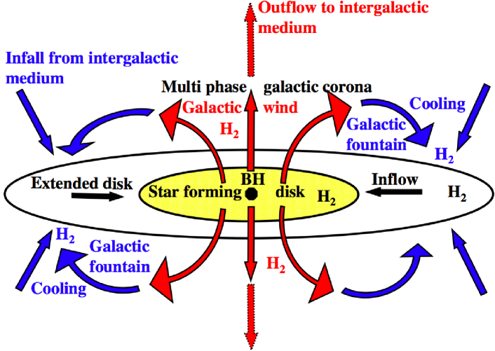
Understanding galaxy formation will be a major challenge for many years to come. Although the observational basis has been growing steadily, we have only started to come to some understanding of the physics that gives rise to the observed numbers, masses, morphologies and chemical composition of galaxies as a function of cosmic environment and time. The growth of galaxies depends on their mass and environment and the evolution of the gas within dark matter haloes. The build-up of baryonic mass in galaxies is regulated by a complex interplay of energy and matter between different gas phases. It is affected by the formation of stars, massive central black holes and flows in and out of galactic disks and haloes (Fig. 1). H2 is present in all stages because its formation is a natural outcome of gas cooling, and because stars are made from this phase of matter.
is designed to survey galactic-scale H2 emission associated with star formation, gas accretion and feedback, as well as spectroscopic fingerprints (dust features, ionized gas lines) of a large number of infrared luminous galaxies. Space Telescope and Infrared Space Observatory () observations have revealed a new class of extremely luminous molecular hydrogen emission galaxies with L(H2) = 1040 – in pure rotational molecular hydrogen emission lines but with relatively weak total IR emission, rigopoulou ; appleton ; egami ; ogle . In these galaxies, the S(5) line at 6.9 m is observed to be comparably bright to the S(1) and S(3) lines. can observe this line up to a redshift of 2.5. Its unique ability to do wide-field spectroscopic surveys in the infrared places it as a key player in the opening up of cosmic discovery space.
2.2 What is the H2 contribution to the missing baryons?
Galaxies dynamics and weak lensing surveys suggest that a significant fraction of the dark matter in the Universe is in the virialized haloes of 222Break in the Schechter’ galaxies luminosity function schechter galaxies but the observed mass in condensed baryons – stars and gas – is only about 8% of the total fuku_peebles04 . Intergalactic shocks may have made some of the baryons too hot to fall into dark matter haloes. This interpretation is supported by evidence that a substantial amount of baryons is in the warm-hot intergalactic medium, with temperatures in the range 105–107 K dave . For galaxies like the Milky Way – far from massive cosmic structures – it is more likely that much of their baryonic mass has been blown out of their disks, possibly out of their haloes, or may be hidden from view. is designed to test two aspects of the missing baryons problem. (1) A survey in the local Universe will test whether many of the missing baryons could be H2 gas hiding in the extended disk and/or haloes of galaxies. This gas would have escaped detection through CO observations because of its low metallicity and clumpiness. In low-metallicity regions, the H2 rotational lines are the main pathway through which the gas cools. So a deep unbiased search for H2 emission provides a unique means to test this possibility. (2) spectroscopic imaging of galactic winds in local Universe starburst galaxies and active galactic nuclei will quantify the energy radiated, and the mass and kinetic energy carried by molecular gas. They will complement optical to X-ray observations that only probe the warm and hot ionized components of galactic winds.
2.3 What controls star formation efficiency?
Star formation is the end-process of a multiscale condensation of gas under the effect of gravity. It is controlled by the dissipation of interstellar turbulent kinetic energy in molecular clouds which allows gravity to take over. Once stars have formed, their feedback through jets and winds, stabilizes their nascent cloud. Milky Way and local group observations of H2 will probe molecular cloud energetics from their formation out of the diffuse interstellar medium to their dispersal by massive stars. will measure the rate of condensation of diffuse matter towards gravitationally bound molecular clouds. It will also reveal the molecular component of star forming regions that carries most of the momentum provided by stellar feedback.
2.4 How do giant planets form?
Planets are thought to form in the circumstellar disks that surround proto-stars and pre-main-sequence stars. H2 dominates the disks mass and dynamics. Two main scenarios are proposed for the formation of giant planets: gas accretion onto massive rocky cores or direct formation out of the gas as a result of gravitational instability. In the simplest scenario, the core accretion process requires that H2 is present at late stages. The gravitational instability mechanism predicts formation at earlier times out of a very massive H2 disk. To constrain the planet formation scenarios it is imperative to obtain direct observational evidence on the disk H2 content and how long it lasts. offers the required combination of field and spectral resolution to survey young star clusters for H2 emission from planet-forming disks.
2.5 Where do complex organic molecules form?
The formation of H2 initiates a network of chemical reactions leading to
an impressive molecular complexity in space. Within the shielded interiors
of dense clouds, molecules stick to grain surfaces which become the sites
of further chemical evolution. Some of these grain surface molecules
become constituents of protoplanetary disks, where they contribute to the
formation of icy planetesimals such as the comets in our Solar System. The
richness of molecular chemistry in dense gas is highlighted by observations
of large organic molecules in proto-stellar cores heated by nascent stars,
where ices return to the gas. Evolved stars are also known to be sites for
forming large carbonaceous molecules. The evolutionary connection between
these circumstellar species and those in the interstellar gas has yet to be
fully elucidated.
The spectrometer offers the possibility of charting the hidden
roots of complex molecules in space. High resolution mid-infrared
spectroscopy is the only means by which we can detect rovibrational
lines from organic molecules (Cn, HCnH, H2CnH2,
CH3CH2CH3,…) that are the key nodes of organic
chemistry. Such species do not have permanent dipole moments and hence,
have no submillimetric rotational transitions. With its wide field of view,
will also unveil spatial variations of molecular abundances and
thereby the chemical interplay between gas, ices and dust, and their
evolution over time.
3 Legacy Surveys
With the aim of answering the astrophysical questions reviewed above seven Legacy surveys have been defined (Table 3).
| Survey Name | Fields | Area | Sources | Spectral | R | |
|---|---|---|---|---|---|---|
| Number | deg2 | count | domain | |||
| 1) Cosmic Web I | 90 | 10 | 8 - 25m | 102 | ||
| 2) – II | 40 | 4 | 8 - 25m | 103 | ||
| 3) – III | 40 | 4 | S(1), S(2), S(3) | 103 | ||
| 4) Local Universe | 100 | 11 | 100 | S(0), S(1), S(2), S(3) | ||
| 5) Milky Way | 75 | 8.3 | S(0), S(1), S(2), S(3) | 1-3 | ||
| 6) Circumstellar disks | 25 | 2.8 | S(3) | 1-3 | ||
| 7) Astrochemistry | 12 | 1.3 | 8 - 25m | |||
They consist of a dedicated series of targeted observations, each producing data cubes which combine spatial and spectral information with a field of view and spectral resolution appropriate for the science goal. Long integration times (24 to 100 hours/field) to obtain the best sensitivity are planned.
The Cosmic Web surveys
include three wide-field extragalactic surveys with distinct combinations of spectral band and spectral resolution. The low resolution survey (I) is optimized to obtain spectra of dust emission and measure high equivalent width emission lines from the gas. The (II) and (III) medium spectral resolution surveys are optimized to detect H2 and ionic fine structure lines. The wide-band filter survey (II) covers all redshifts. The narrow bands survey (III) enables optimal sensitivity targeting for specific Cosmic Web structures at selected redshifts.
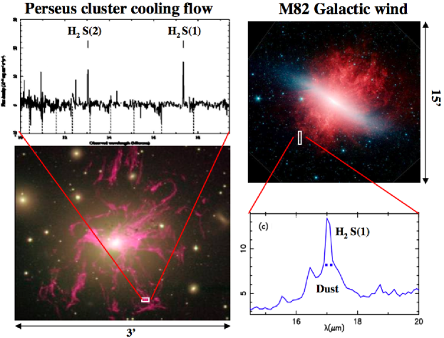
The Local Universe survey
comprises observations of 100 extragalactic sources sampling galaxy types and extragalactic environments, including active galactic nuclei, interacting galaxies, groups and nearby clusters with cooling flows (e.g. the Perseus A cooling flow and the M82 starburst galaxy in Fig. 2). H2 will be observed over the whole extent of the sources, including galaxies extended disk and haloes with a spectral resolution of to measure the gas velocity. Such a deep search for low brightness molecular gas in galaxies would have a major impact on our understanding of the dynamical and chemical evolution of galaxies and star formation.
The Milky Way survey
will include the full diversity of galactic environments, diffuse ISM, giant molecular clouds with photo-dissociation regions and shocks around massive YSOs, supernovae remnants, planetary nebulae, the Galactic Center. Each of these regions offers a specific class of problem due to the various natures of the sources of excitation. Detailed studies of H2 in galactic environments will ground the interpretation of observations of distant galaxies. The observations will be performed with the highest spectral resolution to resolve the H2 line profiles, making possible to reach the turbulence conditions and the global kinematics of the gas in all these environments. Ionic lines present in the same filter bandpasses will be a complementary indication on the physical conditions in different parts of each field.
The Circumstellar Disks survey
will target clusters within a few 100 pc from the Sun, spanning a range of ages from 1 to several 10 Myr. These measurements will constrain the age at which gas giant planets are forming. They will be performed with the highest spectral resolution to obtain the needed spectral contrast to detect H2 rotational line emission from proto-planetary disks and to measure the line width and thereby, the Keplerian radius at which the emission originates. The field of view matches the angular extent of nearby star clusters. It will permit the simultaneous observation of a large ( per field) number of young stellar objects in various stages of their evolution. The large number of objects will allow us to capture the short evolutionary time span when the inner, planet forming part of the disk becomes optically thin in the dust, but gas accretion on planets has yet to occur.
The Astrochemistry survey
will use the large spectral coverage to detect minor gaseous molecular constituents, organic molecules that lack microwave rotational transitions, and ices, like CO2, by their absorption signatures against bright extended sources. Observations of stellar clusters will provide unprecedented statistics on solid matter in young stellar objects. The heavier isotope, HD has its higher J¯4-3, 5-4 and 6-5 lines occurring at 28.5, 23.0 and 19.4 µm. These line have been observed with and by Bertoldi99 and Neufeld06 in Galactic star forming regions and the IC 443 supernova remnant. Two of these HD lines are within the spectral range of the S(0) and S(1) of H2 observations. HD detections will be used in combination with H2 data to measure the abundance ratio [HD/H2] across the Galaxy and in distant galaxies.
4 The science requirements
Through the legacy surveys the payload design and operations of are driven by the following science requirements:
1.
The detection of the first pure rotational emission lines 0 – 0 S(0), S(1), S(2) and S(3) of H2 imposes a wavelength coverage at least from 9 to 29 m.
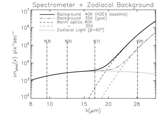
2.
The program must be conducted from space because only S(1) at 17.0 m, and S(2) at 12.3 m are reasonably accessible, from a very good infrared site of high altitude. In any case, the sensitivity for the rotational H2 lines observable from ground is limited by the strong thermal background from the sky and the telescope at these wavelengths. For an optimum sensitivity in the mid-infrared, the solution prepared for and also for and , consists of placing the spacecraft at the L2 point of the Sun-Earth system, to allow zodiacal-light-limited performance. However, for an equilibrium temperature of 40 K the thermal background from the payload becomes prominent beyond 20 m (Fig. 3). A temperature of 35 K would be preferable, and is considered as a goal.
3.
The study of the complete distribution of H2 in extended regions like the intergalactic medium of galaxy clusters, in the halo of nearby galaxies, in giant molecular clouds, calls for an instrument able to map a wide field to perform unbiased surveys. A value between 10 and 30’ field seems a good compromise. Thus, a wide-field integral field spectrometer (IFS) is the most suited instrument, which from the spectroscopy in all points of a field makes possible imagery in specific spectral lines.
4.
Only a spectroscopic method of detection of the emission lines makes possible to separate with a high contrast the lines from the continuum, to resolve the line profiles making possible to derive the kinematics, multiple velocity components and the physical conditions. The line widths to measure can go from a few km s-1 in the local interstellar medium to several hundreds of km s-1 in external galaxies, which requires a flexibility in the choice of resolving power.
5.
It is desirable to improve the spatial resolution of missions like and in the same spectral range, which had telescope sizes respectively of 60 and 85 cm. A diameter of 1.2 m would give a diffraction limit of 2” (FWHM) at 9.7 m, improving the contrast in the detection of compact objects against their environment and against the parasitic background.
5 The instrumental solution
Imaging spectroscopy in the infrared can be achieved using different techniques maillard_pasp , a long slit grating spectrometer with or without an image slicer (integral field unit), a Fabry-Perot (FP) and an imaging Fourier transform Spectrometer (IFTS). The possible combination of field coverage, spectral resolution and spectral coverage with respect to the scientific requirements oriented the final choice towards the Imaging FTS as offering the following advantages, of interest for : - direct imaging of a wide field, yielding the best image quality (no image reconstruction), which also relaxes the pointing tolerances compared with the slit spectrometer used in mapping mode, - high spectral resolution on a wide field. This point made a decisive element in the choice, - large multichannel advantage by the simultaneous observation of a huge number of spectra, - complete flexibility in the choice of spectral resolution, from a few hundreds up to several tens of thousand, within the range determined by the maximum attainable optical path difference (OPD), - large spectral coverage with a single instrument, important advantage for a mission as , - absolute wavelength calibration of all the spectra from the reference laser line used to control the OPD.
As for any spectroscopic instrument, space gives full access to regions totally blocked or strongly perturbed by telluric absorptions in the 8 to 29 m range. The other fundamental benefit is the extremely low thermal background, particularly for a mid-infrared instrument, obtained with the instrument being placed at L2. This condition is of major importance for a FTS, which, by its multiplex properties, is limited in sensitivity by the thermal background integrated over the full bandpass of the entrance filter. This often leads to conclude to a multiplex disadvantage of the FTS. The favorable background conditions in space and the large multichannel advantage from the wide field make possible an optimum sensitivity (Sect. 8). Other advantage of space compared to ground for an imaging instrument, is the absence of image smearing, and of scintillation noise in the intensity measurements due to turbulence. As a consequence, the image resolution can be limited by the telescope diffraction, and the spectral instrumental lineshape be the theoretical sinc function, purely defined by the reached OPD. Last, space enables long observing time of the same field, important for deep surveys at high spectral resolution.
6 Description and key characteristics of the payload
The payload is composed of a telescope and a wide-field Imaging FTS, adapted to cover the 8 to 29 m range.
6.1 General optical design
The IFTS is directly inspired from , the prototype of astronomical IFTS in the near infrared, built for the CFH telescope maillard00 , in operation until 2002. It worked at a high spectral resolution of about 30 000 in the K band, but with a field of view of only 25” diameter. For the matching to a much wider field with the same resolution in the mid-infrared, required a completely new design. An adaptation of the platform developed for the mission proposed to reduce the project risks and cost, and simplify the qualification, integration and test sequences defined the allowed volume and mass. The optical design was driven by the final image quality across the field, with as a goal, to be close to the telescope diffraction limit for the shortest H2 wavelength at 9.7 m. The FTS is a dual output interferometer with a cat’s eye mirror combination in each arm, which are afocal, off-axis reflective systems made of a large concave mirror and a small convex mirror, instead of cube corners traditionnally used. The cat’s eye takes more volume than the cube corner, but has the specific advantage of making possible a pupil imagery within the interferometer, mandatory for a wide-field instrument. Each cat’s eye configured as an Offner relay, reimages 1:1 the entrance pupil made on the beam splitter by the foreoptics, on the beam recombiner. Other interesting property, the secondary mirror is small and can be fastly translated for an active correction of the OPD without moving the entire assembly, which makes possible a high bandpass servo-control system. This property, put in operation on , is proposed to be used in the control of the OPD for (Sect. 7.1).
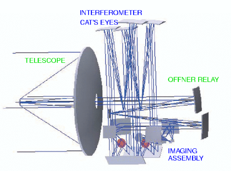
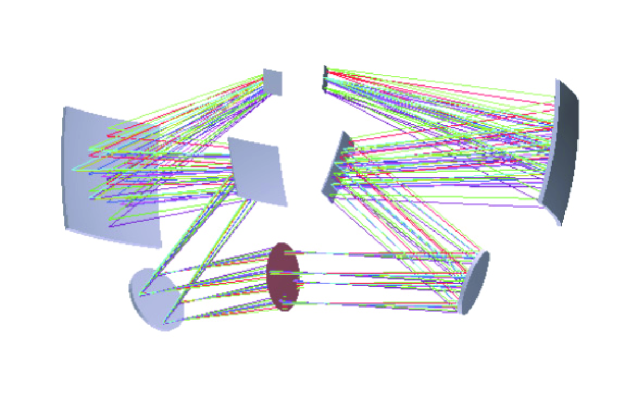
The complete optical combination consists of an afocal Ritchey-Chrétien telescope followed by an Offner relay to provide the parallel beam to the interferometer and make a 1:1 image of the telescope secondary mirror, the entrance pupil, on the beam splitter. The primary mirror has a fast f/ratio (f/0.75) with a diameter of 1.32 m (central hole diameter: 0.21 m) to accept a 20’20’ field of view for a useful beam of 1.20 m, to form a compact telescope (distance primary – secondary: 933 mm). The secondary mirror serves as the entrance pupil in order to minimize the thermal background from the primary mirror. Finally, the main parameters of the payload are summarized in Table LABEL:tab:param.
The maximum OPD has been set to 187 mm to reach a resolving power (R = /d) up to 11 000 at S(0) ( = 354.6 cm-1), which corresponds to a resolution of 32 000 at S(3) ( = 1035 cm-1). In the optical design of the interferometer the two arms are folded by a flat mirror to bring them parallel. With this design the two cat’s eyes can be installed in the same carriage for an OPD change by a push-pull motion of the two arms (Sect. 7.1). The adopted configuration makes the overall size of the payload relatively compact to fit into the platform. The final resulting optical layout of the payload is presented in Fig. 4.
6.3 Beam splitters
The number of non-hygroscopic, transparent optical materials over the entire 8 to 29 m, with the minimum absorption, is very limited. Two materials are available, which can be produced with the required size and which are not hygroscopic, KRS-5 and diamond. They suppose to find the adapted multilayer coating on one side and the AR coating on the opposite side on this very broad spectral range. Hence, a completely different solution is considered, which consists of a beam splitter made from a 3-micron polypropylene film with a multilayer coating. This material has very good transmission properties beyond 8 m and can easily make a 80 mm plate with the appropriate optical quality. This solution has been developed for a spaceborne FTS built by NASA Langley Res. Center, to measure the tropospheric spectrum between 10 and 100 m first . A related technique developed at Cardiff University ade with the same substrate, is based on metal mesh filters, and is mounted on the FTS. These two solutions must be tested to get efficient beam splitters down to 8 m. The realization of the beam splitters is a critical issue of the interferometer, but has possible solutions.
6.4 Imaging assembly
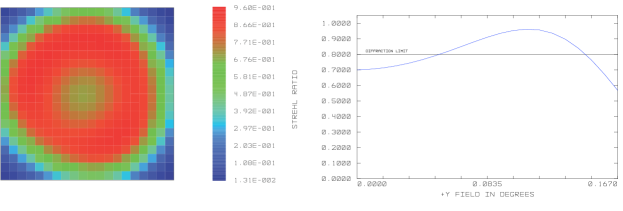
The chosen configuration for each output beam to image the field on a 1K1K detector with 25 microns pitch is a 3-off axis mirror collimator (concave – convex – concave), to make a compact system, with the three mirrors having a common axis (Fig. 5). The pixel size requires a f/4 collimator. The optimization is made with aspheric surfaces. The two detector arrays are mounted back-to-back on the two sides of the same cold head at 5 K. However, this collimating system is limiting the final image quality, which is estimated by the Strehl ratio map shown in Fig. 6. At 10 m the Strehl ratio is comprised between 0.95 and 0.56 over a 10’ radius field. At the extreme corners of the field for this wavelength the Strehl ratio goes down to 0.013 in the worst corner, the astigmatism introduced by the 3-mirror assembly becoming strongly prominent. The Strehl ratio map clearly shows the usable field.
A filter wheel cooled at the same temperature as the detectors, placed between the third mirror (Fig. 5) and the detector makes possible to select the spectral domain of the observation. As indicated in Table LABEL:tab:param a basic set of 9 filters is mounted, with four 2%-band filters, centered respectively on each H2 line. Each of them besides S(0), also represents a specific value for a shorter wavelength H2 line. For example, the S(1) filter corresponds to the S(5) line at z 1.5. A fifth narrow-band filter can be added, for example at 19.4 m to give access to the 0 - 0 R(5) line of HD. Four broad filters are indicated 25%-band in the table to cover the 8 - 25 m domain with adjacent bandpasses. The set is completed by a 8 - 25 m wide-band filter. The longest wavelength of these broad and wide filters is limited to 25 m to avoid entering the region where the thermal background becomes too high (Fig. 3).
6.5 Post-submission optical design
Since the submission of the proposal at the end of June 2007 the optical design has been slightly revised. The current layout implies an afocal telescope. This choice makes the instrument not transposable to a classical Ritchey-Chrétien telescope for further applications. In addition, the telescope secondary mirror diameter is small (equal to the beam splitter diameter) which leads to severe constraints on the mirror positioning (see Sect. 7). A different optical design has been tested maillard_pasp with a f/10 Ritchey-Chrétien telescope, which keeps the same optical design for the interferometer, a comparable overall size of the payload, and with an equal final image quality while removing all the tight tolerances on the telescope building. An aspheric field mirror and an off-axis collimator replace the entrance Offner relay.
7 mechanical design
A first order instrument layout has been studied around the optical configuration (Fig. 4) which is shown in Fig. 7. The telescope and the IFTS, each of them supported by a honeycomb bench, are designed to be assembled and tested separately. The IFTS itself is made of the following sub-systems: entrance Offner relay, cat’s eyes, imaging assembly, which can be aligned separately. All the mirrors for the telescope and the IFTS are fabricated in lightened C/SiC (surface density 15 kg/m2). This composite material presents a high stiffness, a low coefficient of thermal expansion (2.2 10-6/K at room temperature, around 0 at 100 K) and a high coefficient of thermal conductivity. Several space mirrors (, , ) have already been fabricated with this material, the biggest one being the 3.5-m primary mirror made by the combination of 12 pieces. The 1.3-m mirror can be made in a single piece. The secondary mirror of the telescope is linked to the primary by a tripod made of carbon fiber with narrow fins (5 mm thickness) fixed at the back of the secondary, also to limit the thermal background from the unit. Due to the fast f/ratio of the telescope primary mirror (f/0.75), the centering and the focus of the secondary are critical. Its distance to the primary must be precise as mm. The contraction of the carbon fibers from room temperature to 40 K is of the order of 370 m. Then, the focusing of the telescope requires a motorized micrometric focusing mechanism at the back of the secondary, activated on ground for the test operations at room and cryogenic temperature. Before launch the secondary should be blocked for the best focus determined at 40 K. However, this constraint can be cancelled by a different optical design of interferometer foreoptics (see Sect. 6.5).
7.1 OPD control mechanism
The OPD is scanned in a step and look mode which is the heart of the instrument. The two cat’s eyes are mounted as the two parallel sides of a parallelogram (Fig. 8), making possible a push-pull motion which limits the required mechanical course of the carriage to for a maximum OPD variation equal to . In practice, the maximum travel of each cat’s eye is equal to 50 mm. It does not correspond exactly to a maximum OPD of 200 mm, but to 187 mm, since the scans start a little before the zero-OPD to fully cross the main burst of fringes at zero-OPD. Flexural pivots provide frictionless axes. The whole system is perfectly balanced for the minimum reaction on the pointing of the spacecraft. The step-by-step linear displacement of the cat’s eyes is realized from the rotation of a space-qualified endless screw with a 0.5 mm pitch, of 20 mm diameter, mounted in parallel to the optical axis of the cat’s eyes, and a nut with planetary rollers. The motor is activated at each step and is cut during the constant 20 s integration time per image which follows the motion, making negligible the heat load. The distance between the two cat’s eyes produces a very small lateral motion (0.7 mm) for the maximum travel. The rms error on the step size, which must be nm, is reached by a servo-control of the OPD. The light secondary mirror (9090 mm, weight 120 g) of each cat’s eye is mounted on a piezoelectric actuator to provide the needed correction to the displacement given by the step-by-step motor which has a resolution close to 1 micron. As such, the motion of the piezo-actuators is always very small (within 5 to 10 microns) and only requires a low voltage. The piezo-actuators are driven by the real-time measurement of the OPD provided by a near-infrared stabilized laser diode whose beam, injected by optical fiber, is parallel to the science beam coming from the telescope. Such diodes are currently used on several FTSs in space. This type of mechanical displacement and its coupling to piezo-actuators has been in operation for years on the Imaging FTS.

7.2 Thermal design
The cooling of the payload is an important aspect of the performance of the instrument. The design which is chosen is a simplified copy of the architecture developed for the mission since the coolest elements are two Si:As arrays and the two filter wheels, operating at K. This part is protected from the 40 K emission by a baffle cooled at 18 K. The cooling of the detector box can be made by a JT/Stirling cooler combination as used for MIRI. The 35 K goal can be reached by strictly limiting the heat load of the entire instrument.
7.3 Technology readiness level (TRL)
Several astronomical FTSs have already been put in operation in space. The most famous of them on the Voyager spacecrafts, , returned mid-infrared spectra all along the visit of the four giant planets, from 1979 to 1986. There are currently in space, on Mars Express, on Cassini, on Akari. on Herschel will be launched in 2008. Many other FTSs have been developed for remote sensing of the Earth atmosphere. The most recent, , developed by CNES, which reaches a maximum resolution of 0.35 cm-1, was launched successfully in October 2006. Imaging in the 3.6 to 15.5 m range is obtained by a scanning the field with 4 single-pixel detectors as the platform moves along its orbit around the Earth. A new generation instrument for the same spectral domain, (Geosynchronous Imaging FTS), part of NASA Earth Observing-3 program, already tested in balloon, is a direct imager as .
| Sub-system | Heritage | TRL | ||
|---|---|---|---|---|
| C/SiC Telescope | Herschel, Gaia | 8 | ||
| OPD control system | BEAR, GIFTS | 6, 7 | ||
| Beam splitter | FIRST, SPIRE | 9 | ||
| diode laser | IASI, GIFTS | 9 | ||
| Filter wheels | ISO, MIRI | 9, 8 | ||
| Si:As detector | MIRI, WISE | 8 | ||
| Cryogenics | Planck, MIRI | 8, 6 | ||
| Data compression | Mars Express | 9 | ||
The instrument has given a solid experience on the type of data which will be acquired by , with the development of a complete chain of programs, from the raw data to the calibrated spectral cube, which has just to be adapted to the fields. The challenge consists of building an Imaging FTS with a similar resolution but with a much wider field and to bring it to space. Other aspects as filter wheels, infrared detectors, cryo-generators, are common to other infrared space missions. From all this experience, in Table 7.3 are listed the main sub-systems, showing that for all of them their TRL is .
8 sensitivity
From the design of the payload a careful analysis of the the minimum detectable flux has been conducted. For sufficiently long integrations, the limit of sensitivity is dominated by the background photon noise. The parasitic flux in space is the sum of the zodiacal light and the thermal emission from the payload at L2 (Fig. 3). The entrance field is imaged on two detector arrays, the two complementary outputs of the interferometer. To obtain the final sensitivity, the noise on each pixel of the detector area over which the flux is integrated is added quadratically and the signal is the sum of the two complementary output flux. The optical throughput and the optics emissivity for each output beam used for the sensitivity calculations, taking into account all the optical elements (see maillard_pasp for details), are given in Table 4. Two observing cases have been considered: extended gaseous regions and point sources. The main results are presented in Table 8 for six combinations of filter bandwidth and resolution, which have been defined for the surveys (Table 3).
| Optics temperature | 40 K |
|---|---|
| Filter temperature | 5 - 6 K |
| Mirror reflectivity | (gold-coated) |
| Beam splitter transmission | |
| – reflection | |
| – absorption | |
| Optical throughput | = 0.39(1) |
| Optics emissivity | = 0.17(1) |
| Peak filter transmission | 0.8 |
| Detector QE | 0.5 for m, 0.13(2) at 28.2 m |
| Well capacity | 2 |
| Readout noise | 20 |
| Dark current | 10 |
| : same results for and | |
| : with AR coating peaked at 28 m | |
| : by measuring fluxes with a 2.7 s frame time | |
For high spectral resolution work the observing strategy consists of using high-peak transmission 2% narrow-band filters to isolate each observed H2 emission line. The sky background flux from space and the thermal emission from the low-emissivity cold instrument (Fig. 3), within the narrow bandpass, form the incoming flux which limits the sensitivity. Since emission lines are observed, the signal-to-noise ratio for the peak of the emission line is independent of the resolution, as long as the line is not resolved. Finally, the line contrast is improved by increasing the resolution. These three conditions: 1) narrow-band filter in low-background environment, 2) lines in emission, 3) high spectral resolution, provide the optimum sensitivity to the Imaging FTS.
| Mode | Filter | Obs. | Targets | Tracer | D1(1)/Goal(2) | D2(1) | ||
| width | time (h) | |||||||
| 1 | 2% | 11 000 | 24 | star form. regions | H2 | 5.0(3)/1.3(3) | 1.5(3) | |
| nearby galaxies | H2 | |||||||
| 2 | 2% | 11 000 | 100 | star form. regions | H2 | 29/6.8 | 3.5 | |
| circumstel. disks | H2 | |||||||
| 3 | 2% | 1000 | 100 | distant galaxies | H2 | 1.3 | ||
| 4 | 25% | 1000 | 100 | distant galaxies | ions | 8.1/4.5 | 4.3 | |
| H2 | ||||||||
| 5 | 25% | 10000 | 24 | Mol. Clouds | molecules | 16/9.0 | 8.6 | |
| 6 | 8 - 25 m | 100 | 36 | distant galaxies | dust | 60/36 Jy | ||
| : 5 detectivity in 10W m-2 D1 for S(0) and the 25% 23 m filter, D2 for the other filters | ||||||||
| : D1 for passive cooling at 35 K and QE = 50% beyond 26 m (Si:P detectors instead of Si:As) | ||||||||
| : 5 detectivity in 10 W m-2 sr-1 in a 5” 5”area | ||||||||
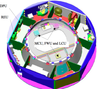
9 The spacecraft and the mission profile
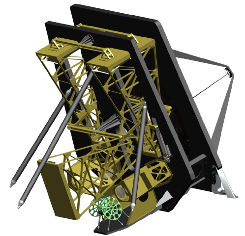
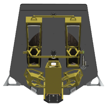
The payload to be installed in the spacecraft is shown in Fig. 9 (right) and the Service Module in Fig. 9 (left). The Service Module of the platform is formed by an octagonal box built around a conical tube that supports the module cryo-structure, and with on top, an hexagonal frame which supports the payload by three legs (Fig. 7). The payload has been designed to comply with this configuration. The baseline cryogenic chain is derived from . The passive radiator based on the 3 V-Groove insulation system meets the 40 K requirement on the telescope and spectrometer optics, with the hope to be able to reach 35 K by limiting the internal heat lift. For the detectors, one JPL H2 sorption cooler ensures an intermediate 18 K stage and two RAL He Joule-Thompson 4 K coolers working at 50% of their full capacity provide the necessary cooling power. The interfaces between the passive radiators and active coolers remain the same as for .
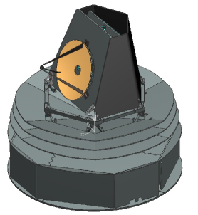
A shield with the solar array on the bottom of the service module maintains the necessary shadowing cone. The orientation of the telescope permits to access most of the sky outside a narrow region around the ecliptic poles. A given position within the accessible sky can be observed twice a year for a duration of at least 10 days. The qualified Attitude and Orbit Control System (AOCS) complies with the three axis stabilized pointing requirement (absolute pointing error 30”, pointing stability 0.5”over 20 s). This adds four reaction wheels and one internally redundant gyroscope to the AOCS sub-system. The use of a SOYUZ-Fregat launcher instead of an ARIANE V for requires a launcher adapter and diameter reduction: 420mm for the solar array and 40 mm for the structure.
The scientific program (Table 3) is designed for a nominal 2 years mission, which could be extended since the lifetime is not limited by cryogenic fluids. is an explorer type mission by its instantaneous field size but the surveys require long (24 hours) pointing for each field. The operations are closer to those of a space observatory like than of all-sky survey missions such as .
10 in context
To evaluate the scientific interest of the proposed instrument must be replaced in context of other infrared facilities also able to observe the H2 rotational lines. With a maximum resolving power around 3000, , the mid-infrared integral-field spectrometer wright will cover the full 5 – 29 m range in four channels associated to different small fields from 3.0”3.9” to 6.7”7.7”. The main characteristics is the high resolution image sampling, going from 0.19 to 0.27”/pixel. On ground, lacy ; bitner and its copy on richterm provide a high spectral resolution, up to 105 on the 5 – 25 m domain. Sensitivity is limited by the sky emission. The spectral coverage is very narrow, of 0.5%, and the slit length is small, typically from 6 to 12” depending on the wavelength range. Another mode at medium resolution (15 000) provides a slit of 1.5”45”. These two types of instrument, and are designed for targeted studies of distant galaxies, ULIRGs and AGNs, of multiple stellar systems, of circumstellar disks, but are not suited for the observation of extended sources, or to complete a survey of these different targets over a wide field. The limited spectral resolution in the case of will not make possible to access the dynamics of star forming regions.
| Instrument/ | Ang. Res. | R | Field of | Point(1) | Extended(2) | |
|---|---|---|---|---|---|---|
| Telescope | FWHM (”) | view (”2) | source | emission | ||
| H2EX | 3.6 | 18 000 | 144104 | 7 | 1.5 | |
| IRS-LL/Spitzer | 5.0 | 80 | 756 | 38 | 6 | |
| IRS-SH/Spitzer | 5.3 | 600 | 54 | 20 | 3 | |
| MIRI/JWST | 0.7 | 3000 | 52 | 0.5 | - | |
| TEXES/Gemini | 1.0 | 80 000 | 12 | 650 | - | |
| TEXES/Gemini | 1.5 | 15 000 | 67 | 50 | - | |
| EXES/SOFIA | 1.7 | 80 000 | 12 | 650 | - | |
| MIR/Spica(3) | 1.4 | 3000 | 1800 | 1.5 | 0.6 | |
| 5 sensitivity, 5” spatial resolution in 3 hrs, unit 10-20 W m-2. | ||||||
| 5 sensitivity, 5” spatial resolution in 3 hrs, unit 10-10 W m-2 sr-1 | ||||||
| Courtesy of B. Swinyard | ||||||
The uniqueness of is demonstrated in Table 10 where we use the S(1) rotational line to compare space and ground-based infrared facilities. The instantaneous field of view of is more than twenty thousand times larger than that of the high spectral resolution mode and . In addition, the highest spectral resolution mode of is 50 times that of the smaller-area high resolution slits of and 6 times that of .
11 Conclusion
is devoted to the detection of the first rotational lines of molecular hydrogen, through a series of targeted surveys, going from the Cosmic Web to the circumstellar disks in the solar neighborhood, and the formation of complex molecules. Five fundamental aspects of the origin of the luminous universe can be addressed through the proposed surveys. The instrumental novelty of is to offer a flexibility in the spectral resolution choice, from low up to high values of 30 000, that can be tailored to the scientific case, together with a wide field of 20’20’. This capability is missing in the thermal infrared astronomical instrumentation, currently in operation and in preparation. Space is the most favorable place for such an instrument.
Acknowledgements.
The authors greatfully acknowledge help and advices from René Laureijs at ESA who, as former PI, was the early initiator of the new mission. The preparation of the proposal was supported by the Centre National d’Études Spatiales (CNES).References
- (1) Ade, P.A.R., Pisano, G., Tucker, C. & Weaver, S.: Proc. SPIE 6275, 29 (2006)
- (2) Appleton, P.N., Xu, K.C., Reach, W., et al.: ApJ 639, L51 ( 2006)
- (3) Bertoldi, F., Timmermann, R., Rosenthal, D., Drapatz, S., & Wright, C. M.: A&A 346, 267 (1999)
- (4) Bitner, M.A., Richter, M.J., Lacy, J.H., et al.: ApJ 661, L69 (2007)
- (5) Davé, R., Cen, R. et al.: ApJ 552, 473 (2001)
- (6) Egami, E., Rieke, G.H., Fadda, D., & Hines, D.C.: ApJ 652, L21 (2006)
- (7) Engelbracht, C.W., Kundurthuy, P., Gordon, K.D. et al.: ApJ 642 (2006)
- (8) Fukugita, M. & Peebles, P.J.E.: ApJ 616, 643 (2004)
- (9) Johnstone, R., Hatch, N., Ferland, G. et al.: MNRAS accepted and astro-ph/0702431 (2007)
- (10) Lacy, J.H., Richter, M.J., Greathouse, T.K., et al.: PASP 114, 153 (2002)
- (11) Maillard, J.P.: in Imaging the Universe in 3D, ed. W. van Breugel & J. Bland-Hawthorn, ASP Conf. Series, 195, 185 (2000)
- (12) Maillard, J.P., Boulanger, F. & Y. Longval: PASP accepted (2008)
- (13) Mlynczak, M.G., Johnson, D.G., Latvakoski, H., Jucks, K.W., et al.: GeoRL 33, 707 (2006)
- (14) Neufeld, D.A., Green, J.D., Hollenbach, D. et al.: ApJ 647, L33 (2006)
- (15) Ogle, P., Antonucci, R., Appleton, P.N., & Whysong, D.: ApJ 668, 699 (2007)
- (16) Richter, M.J., Lacy, J.H., Jaffe, D.T. et al.: Proc. SPIE 4014, 54 (2000) and www.as.utexas.edu/astronomy/research/exes.html
- (17) Rigopoulou, D., Kunze, D., Lutz, D., Genzel, R. & Moorwood, A.F.M.: A&A 389, 374 (2002)
- (18) Schechter, P.: ApJ 203, 297 (1976)
- (19) Wright, G.S., et al.: Proc. SPIE 5487, 653 (2004)