New Mechanics of Traumatic Brain Injury
Abstract
The prediction and prevention of traumatic brain injury is a very important aspect of preventive medical science. This paper proposes a new coupled loading–rate hypothesis for the traumatic brain injury (TBI), which states that the main cause of the TBI is an external Euclidean jolt, or jolt, an impulsive loading that strikes the head in several coupled degrees-of-freedom simultaneously. To show this, based on the previously defined covariant force law, we formulate the coupled Newton–Euler dynamics of brain’s micro-motions within the cerebrospinal fluid and derive from it the coupled jolt dynamics. The jolt is a cause of the TBI in two forms of brain’s rapid discontinuous deformations: translational dislocations and rotational disclinations. Brain’s dislocations and disclinations, caused by the jolt, are described using the Cosserat multipolar viscoelastic continuum brain model.
Keywords: Traumatic brain injuries, coupled loading–rate hypothesis, Euclidean jolt, coupled Newton–Euler dynamics, brain’s dislocations and disclinations
1 Introduction
Traumatic brain injury (TBI) continues to be a major health problem, with over 500,000 cases per year with a societal cost of approximately $85 billion in the US. Motor vehicle accidents are the leading cause of such injuries. In many cases of TBI widespread disruption of the axons occurs through a process known as diffuse axonal injury (DAI) or traumatic axonal injury (TAI) [Singh et al 2006]. TBI occurs when physical trauma causes brain damage, which can result from a closed head injury111A closed injury occurs when the head suddenly and violently hits an object but the object does not break through the skull. or a penetrating head injury.222A penetrating injury occurs when an object pierces the skull and enters brain tissue. In both cases, TBI is caused by rapid deformation of the brain, resulting in a cascade of pathological events and ultimately neuro-degeneration. Understanding how the biomechanics of brain deformation leads to tissue damage remains a considerable challenge [Morrison et al 2006].
Parts of the brain that can be damaged include the cerebral hemispheres, cerebellum, and brain stem. TBI can cause a host of physical, cognitive, emotional, and social effects [NIH 2002, Rapp 2008]. Half of all TBIs are due to transportation accidents involving automobiles, motorcycles, bicycles, and pedestrians. These accidents are the major cause of TBI in people under age 75. For those aged 75 and older, falls cause the majority of TBIs. Approximately 20 % of TBIs are due to violence, such as firearm assaults and child abuse, and about 3% are due to sports injuries. Fully half of TBI incidents involve alcohol use [NIH 2002]. TBI is a frequent cause of major long-term disability in individuals surviving head injuries sustained in war zones. This is becoming an issue of growing concern in modern warfare in which rapid deployment of acute interventions are effective in saving the lives of combatants with significant head injuries. Traumatic brain injury has been identified as the ‘signature injury’ among wounded soldiers of the current military engagement in Iraq [Mason 2007, Hoge 2008]. Rapid deformation of brain matter caused by skull acceleration is most likely the cause of concussion, as well as more severe TBI. The inability to measure deformation directly has led to disagreement and confusion about the biomechanics of concussion and TBI [Bayly et al 2005].
TBI can be mild, moderate, or severe, depending on the extent of the damage to the brain. Outcome can be anything from complete recovery to permanent disability or death (see [Chen et al 2008]). Some symptoms are evident immediately, while others do not surface until several days or weeks after the injury [NIH 2002]. With mild TBI, the patient may remain conscious or may lose consciousness for a few seconds or minutes; the person may also feel dazed or not like him- or herself for several days or weeks after the initial injury; other symptoms include: headache, mental confusion, lightheadedness, dizziness, double vision, blurred vision (or tired eyes), ringing in the ears, bad taste in the mouth, fatigue or lethargy, a change in sleep patterns, behavioral or mood changes, trouble with memory/concentration/calculation. With moderate or severe TBI, the patient may show these same symptoms, but may also have: loss of consciousness, personality change, a severe/persistent/worsening headache, repeated vomiting/nausea, seizures, inability to awaken, dilation (widening) of one or both pupils, slurred speech, weakness/numbness in the extremities, loss of coordination, increased confusion, restlessness/agitation; vomiting and neurological deficit together are important indicators of prognosis and their presence may warrant early CT scanning and neurosurgical intervention.
In particular, standard medical statistics suggest that the loss of consciousness in boxing knock-outs and road–vehicle crashes is caused by rotation of the brain–stem [Misra and Chakravarty 1984] as a dynamic response [Ivancevic and Ivancevic 2006a, Ivancevic and Ivancevic 2007d] of a head–neck system to an impulsive load [Misra and Chakravarty 1985]. It is generally associated to the following three syndromes: Locked-In, Semi-Coma, and Akinetic Mute, all three characterized by the total loss of gesture, speech and movement. The cognitive abilities [Ivancevic and Ivancevic 2007c, Ivancevic and Aidman 2007] can still be intact, but the patient cannot express himself by either speech or gesture. Recall that the brain stem, including Midbrain, Pons and Medulla Oblongata, is located at the base of the brain. It is the connection between the cortex and the spinal cord, containing motor neural pathways for voluntary movement from the upper part of the brain. The brain stem also controls such automatic functions as breathing, heart rate, blood pressure, swallowing, sleep patterns and body temperature. Weaker injuries include another three symptoms: abnormal respiration (hyperventilation and abnormal breathing patterns: ataxic, clustered, hiccups); pupils: dilated, fixed; and movement (if any): abnormal extensor.
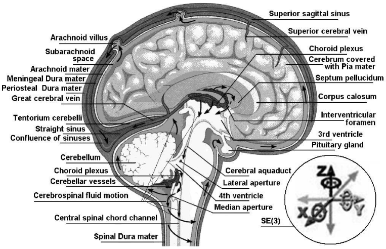
The natural cushion that protects the brain from trauma is the cerebrospinal fluid (CSF). It resides within cranial and spinal cavities and moves in a pulsatile fashion to and from the cranial cavity (see Figure 1). This motion can be measured by functional magnetic resonance imaging (fMRI, see [Sokoloff 2008] for a review) and may be of clinical importance in the diagnosis of several brain and spinal cord disorders such as hydrocephalus, Chiari malformation, and syringomyelia. It was found in [Maier et al 1994] that brain and CSF of healthy volunteers exhibited periodic motion in the frequency range of normal heart rate. Both brain hemispheres showed periodic squeezing of the ventricles, with peak velocities up to 1 mm/sec followed by a slower recoil. Superimposed on the regular displacement of the brain stem was a slow, respiratory-related periodic shift of the neutral position. During the Valsalva maneuver, the brain stem showed initial caudal and subsequent cranial displacement of 2-3 mm. Coughing produced a short swing of CSF in the cephalic direction. The pressure gradient waveform of a linearized Navier-Stokes model of the pulsatile CSF flow was found in [Loth et al 2001] to be almost exclusively dependent on the flow waveform and cross-sectional area.
The state of head injury biomechanics:: past, present, and future was presented in [Goldsmith 2001], dealing with components and geometry of the human head, classification of head injuries, tolerance considerations, head motion and load characterization, experimental dynamic loading of human living and cadaver heads, dynamic loading of surrogate heads, and head injury mechanics. The subsequent paper [Goldsmith and Monson 2005] described physical head injury experimentation involving animals (primarily primates), human cadavers, volunteers, and inanimate physical models.
Besides motor accidents, concussion (or mild TBI), occurs in many activities, mostly as a result of the head being accelerated. For example, although a popular endeavor, boxing has fallen under increased scrutiny because of its association with TBI. The injury rate in professional boxing matches is high, particularly among male boxers. Superficial facial lacerations are the most common injury reported. Male boxers have a higher rate of knockout and technical knockouts than female boxers [Bledsoe et al 2005]. Although the epidemiology and mechanics of concussion in sports have been investigated for many years, the biomechanical factors that contribute to mild TBI remain unclear because of the difficulties in measuring impact events in the field. The objective of [Beckwith et al 2007] was to validate an instrumented boxing headgear (IBH) that can be used to measure impact severity and location during play. Based on this study, the IBH is a valid system for measuring head acceleration and impact location that can be integrated into training and competition. Similarly, a comprehensive study has been conducted by [Newman et al 2005] to understand better the mechanics of the impacts associated with concussion in American football, involving a sequence of techniques to analyze and reconstruct many different head impact scenarios.
Impact biomechanics from boxing punches causing translational and rotational head acceleration was experimentally studied in [Viano et al 2005]. Olympic boxers threw four different punches at an instrumented Hybrid III dummy and responses were compared with laboratory-reconstructed NFL concussions. Instrumentation included translational and rotational head acceleration and neck loads in the dummy. Biaxial acceleration was measured in the boxer’s hand to determine punch force. Hybrid III dummy head responses and FE brain modelling were compared to similarly determined responses from reconstructed concussions in professional NFL football players. The hook produced the highest change in hand velocity (11.0 +/- 3.4 m/s) and greatest punch force (4405 +/- 2318 N) with average neck load of 855 +/- 537 N. It caused head translational and rotational accelerations of 71.2 +/- 32.2 g and 9306 +/- 4485 . These levels are consistent with those causing concussion in NFL impacts. However, the head injury criterion (HIC) for boxing punches was lower than for NFL concussions because of shorter duration acceleration. Boxers deliver punches with proportionately more rotational than translational acceleration than in football concussion. Boxing punches have a 65 mm effective radius from the head cg, which is almost double the 34 mm in football. A smaller radius in football prevents the helmets from sliding off each other in a tackle. Similarly, impacts causing concussion in professional football were simulated in laboratory tests to determine collision mechanics [Viano et al 2007]. This study focused on the biomechanics of concussion in the struck player, addressing head responses causing concussion in the NFL players.
Head injury mechanisms are difficult to study experimentally due
to the variety of impact conditions involved, as well as ethical
issues, such as the use of human cadavers and animals
[Krabbel and Appel 1995]. A number of finite element (FE) models and
analysis studies have been conducted in order to understand the
mechanism of TBI. An FE analysis was carried out in [Chu et al 1994]
to study the mechanism of cerebral contusion. Clinical findings
indicate that most cerebral contusions in the absence of skull
fracture occur at the frontal and temporal lobes. To explain these
observations, cavitation and shear strain theories have long been
advocated. Plane strain finite element models of a para-sagittal
section of the human head were developed in the present study. The
model was first validated against a set of experimental results
from the literature. Frontal and occipital impacts were then
simulated, and pressure and shear stress distributions in the
brain were compared. While comparable negative pressures always
developed in the contrecoup regions, shear stress distributions
remained nearly identical regardless of the impact direction,
consistent with the clinically observed pattern for contusion.
Therefore, shear strain theory appeared to account better for the
clinical findings in cerebral contusion.
A 3D FE model based on the anatomical features of the adult human cranium was developed in [Krabbel and Appel 1995]. The complex cranial geometry was measured from a series of 2D computer tomography images. The CT scans were transformed with a self-developed preprocessor into a finite element mesh. A review of the existing FE models was presented in [Voo et al 1996] for the biomechanics of human head injury. More recent models incorporated anatomic details with higher precision. The cervical vertebral column and spinal cord were included. Model results had been more qualitative than quantitative owing to the lack of adequate experimental validation. Advances included transient stress distribution in the brain tissue, frequency responses, effects of boundary conditions, pressure release mechanism of the foramen magnum and the spinal cord, verification of rotation and cavitation theories of brain injury, and protective effects of helmets. These theoretical results provided a basic understanding of the internal biomechanical responses of the head under various dynamic loading conditions. The mechanism of brain contusion has been investigated in in [Huang et al 2000] using a series of 3D FE analyses. A head injury model was used to simulate forward and backward rotation around the upper cervical vertebra. Intracranial pressure and shear stress responses were calculated and compared. The results obtained with this model support the predictions of cavitation theory that a pressure gradient develops in the brain during indirect impact. Contrecoup pressure-time histories in the para-sagittal plane demonstrated that an indirect impact induced a smaller intracranial pressure (-53.7 kPa for backward rotation, and -65.5 kPa for forward rotation) than that caused by a direct impact. Comparison of brain responses between frontal and lateral impacts was performed in [Zhang et al 2001] by FE modelling. Identical impact and boundary conditions were used for both the frontal and lateral impact simulations. Intracranial pressure and localized shear stress distributions predicted from these impacts were analyzed. The model predicted higher positive pressures accompanied by a relatively large localized skull deformation at the impact site from a lateral impact when compared to a frontal impact. Lateral impact also induced higher localized shear stress in the core regions of the brain.
A nonlinear viscoelastic FE model for brain tissue was developed in [Brands et al 2004]. To obtain sufficient numerical accuracy for modelling the nearly incompressible brain tissue, deviatoric and volumetric stress contributions were separated. Deviatoric stress was modelled in a nonlinear viscoelastic differential form. An attempt was made in [Zhang et al 2004] to delineate actual injury causation and establish a meaningful injury criterion through the use of the actual field accident data. Twenty-four head-to-head field collisions that occurred in professional football games were duplicated using a validated FE human head model. The injury predictors and injury levels were analyzed based on resulting brain tissue responses and were correlated with the site and occurrence of mild TBI. Predictions indicated that the shear stress around the brainstem region could be an injury predictor for concussion. The controlled cortical impact model has been used extensively to study focal traumatic brain injury. Although the impact variables can be well defined, little is known about the biomechanical trauma as delivered to different brain regions. The FE analysis based on high resolution T2-weighted MRI images of rat brain was used in [Pena et al 2005] to simulate displacement, mean stress, and shear stress of brain during impact. Young’s Modulus E, to describe tissue elasticity, was assigned to each FE in three scenarios: in a constant fashion (E = 50 kPa), or according to the MRI intensity in a linear (E = [10, 100] kPa) and inverse-linear fashion (E = [100, 10] kPa). Simulated tissue displacement did not vary between the 3 scenarios, however mean stress and shear stress were largely different. The linear scenario showed the most likely distribution of stresses.
A detailed FE model of the rat brain was developed in [Mao et al 2006] for the prediction of intracranial responses due to different impact scenarios. The FE model was used to predict biomechanical responses within the brain due to controlled cortical impacts (CCI). A total of six different series of CCI studies, four with unilateral craniotomy and two with bilateral craniotomy, were simulated and the results were systematically analyzed, including strain, strain rate and pressure within the rat brain. Simulation results indicated that intracranial strains best correlated with experimentally obtained injuries. An automating meshing method for patient-specific FE model was developed in [Guan et al 2006]. 3D geometries of two six-month-old infant heads were reconstructed from the CT data. FE meshes including cranial bone of skull, brain, and suture were generated. Both static and dynamic analyzes were performed to verify the models. The study for blunt impact of infant head was performed by using these patient-specific models.
A 3D FE analysis of human head was performed in [Zong et al 2006], to assess injury likelihood of the head subjected to impact loading. The structural intensity (SI) methodology333SI is a vector quantity indicating the direction and magnitude of power flow inside a dynamically loaded structure. was introduced in accordance with the prevailing practice in experimental biomechanics. The SI field inside the head model was computed for three frontal, rear and side impacts. The results for the three cases revealed that there existed power flow paths. The skull was, in general, a good energy flow channel. This study also revealed the high possibility of spinal cord injury due to wave motion inside the head. Recently, a 3D FE analysis was performed in [Takahashi et al 2007] in respect to the frequency analysis of the pressure changes related to TBI. From the results of computer simulations and impact experiments, the authors found similar spectrums in some frequency bands, which indicated the occurrence of the brain injury. A vigorous shaking and an inflicted impact were compared in [Roth et al 2007], defined as the terminal portion of a vigorous shaking, using a FE model of a 6-month-old child head. Whereas the calculated values in terms of shearing stress and brain pressure remain different and corroborate the previous studies based on angular and linear velocity and acceleration, the calculated relative brain and skull motions that can be considered at the origin of a subdural haematoma show similar results for the two simulated events. A 2D FE model was developed in [Li et al 2007] with objective to determine localized brain’s strains in lateral impact using finite element modelling and evaluate the role of the falx. Motions and strains from the stress analysis matched well with experimental results from literature. A parametric study was conducted by introducing flexible falx in the finite element model. For the model with the rigid falx, high strains were concentrated in the corpus callosum, whereas for the model with the flexible falx, high strains extended into the cerebral vertex.
On the other hand, it has been a common perception that rapid head rotation is a major cause of brain damage in automobile crashes and falls. A model for rotational acceleration about the center of mass of the rabbit head was presented in [Gutierrez et al 2001], which allowed the study of brain injury without translational acceleration of the head. In the companion paper [Runnerstam et al 2001] it was shown that rotational head acceleration caused extensive subarachnoid hemorrhage, focal tissue bleeding, reactive astrocytosis, and axonal damage. The initial response of the brain after rotational head injury involved brain edema after 24 h and an excitotoxic neuronal micro-environment in the first hour, which leaded to extensive delayed neuronal cell death by apoptosis necrosis in the cerebral cortex, hippocampus and cerebellum. Similarly, the study by [Zhang et al 2006] used the SIMon human FE head model and delineated the contributions of these accelerations using post mortem human subject (PMHS) lateral head impact experimental data. Results indicated that rotational acceleration contributed more than 90% of total strain, and translational acceleration produced minimal strain.
The fidelity of cell culture TBI–simulations that yield tolerance and mechanistic information relies on both the cellular models and mechanical insult parameters. An electro-mechanical cell shearing device was designed by [LaPlaca et al 2005] in order to produce a controlled high strain rate injury (up to 0.50 strain, 30 s(-1) strain rate) that deforms 3D neural cultures (neurons or astrocytes in an extracellular matrix scaffold). Theoretical analysis revealed that these parameters generated a heterogeneous 3D strain field throughout the cultures that was dependent on initial cell orientation within the matrix, resulting in various combinations of normal and shear strain.
Rigid-body modelling (RBM) was used in [Wolfson et al 2005] to investigate the effect of neck stiffness on head motion and head-torso impacts as a possible mechanism of injury. Realistic shaking data obtained from an anthropometric test dummy (ATD) was used to simulate shaking. In each study injury levels for concussion were exceeded, though impact-type characteristics were required to do so in the neck stiffness study. Levels for the type of injury associated with the syndrome were not exceeded.
The nonlinear mechanical behavior of porcine brain tissue in large shear deformations was determined in [Hrapko et al 2006]. An improved method for rotational shear experiments was used, producing an approximately homogeneous strain field and leading to an enhanced accuracy. The model was formulated in terms of a large strain viscoelastic framework and considers nonlinear viscous deformations in combination with non-linear elastic behavior.
The relative motion of the brain with respect to the skull has been widely studied to investigate brain injury mechanisms under impacts, but the motion patterns are not yet thoroughly understood. The study of [Zou et al 2007] analyzed brain motion patterns using the most recent and advanced experimental relative brain/skull motion data collected under low-severity impacts. With a minimum total pseudo-strain energy, the closed-form solutions for rigid body translation and rotation were obtained by matching measured neutral density target (NDT) positions with initial NDT positions. The brain motion was thus separated into rigid body displacement and deformation. The results showed that the brain had nearly pure rigid body displacement at low impact speed. As the impact became more severe, the increased brain motion primarily was due to deformation, while the rigid body displacement was limited in magnitude for both translation and rotation. Under low-severity impacts in the sagittal plane, the rigid body brain translation had a magnitude of 4-5 mm, and the whole brain rotation was on the order of +/-5 degrees.
Biomechanical studies using postmortem human subjects (PMHS) in lateral impact have focused primarily on chest and pelvis injuries, mechanisms, tolerances, and comparison with side impact dummies. The objective of [Yoganandan et al 2008] was to determine lateral impact-induced 3D temporal forces and moments at the head-neck junction and cranial linear and angular accelerations from sled tests using PMHS and compare with responses obtained from an anthropomorphic test device (dummy) designed for lateral impact. Results indicated that profiles of forces and moments at the head-neck junction and cranial accelerations were similar between the two models. However, peak forces and moments at the head-neck junction, as well as peak cranial linear and angular accelerations, were lower in the dummy than PMHS. Peak cranial angular accelerations were suggestive of mild TBI with potential for loss of consciousness.
Deformation of the human brain was measured in vivo by [Sabet et al 2008] in tagged magnetic resonance images (MRI) obtained dynamically during angular acceleration of the head, in order to provide quantitative experimental data to illuminate the mechanics of TBI. Mild angular acceleration was imparted to the skull of a human volunteer inside an MR scanner, using a custom MR-compatible device to constrain motion. Deformation of the brain was characterized quantitatively via Lagrangian strain. Consistent patterns of radial-circumferential shear strain occurred in the brain, similar to those observed in models of a viscoelastic gel cylinder subjected to angular acceleration. It has been noted, however, that strain fields in the brain are clearly mediated by the effects of heterogeneity, divisions between regions of the brain (such as the central fissure and central sulcus) and brain’s tethering and suspension system, including the dura mater, falx cerebri, and tentorium membranes.
The present paper proposes a new approach to brain injury dynamics, phrased as a coupled loading–rate hypothesis for TBI, stating that the main cause of TBI is an external Euclidean jolt, symbolically an jolt, an impulsive loading striking the head in several degrees-of-freedom (both translational and rotational) combined. This new concept is radically different from any of the standard FEM techniques proposed so far for brain injury mechanics (see the above literature review), as well as from any kind of Newton–Eulerian or Lagrangian/Hamiltonian injury dynamics, emphasizing 3 new aspects of brain injury mechanics: (i) coupling of all 6 degrees-of-freedom; (ii) jolt dynamics rather than the force dynamics; and (iii) coupled dislocations/disclinations in the Cosserat multipolar viscoelastic continuum brain model. This new concept is a derivation of our previously defined concept of the covariant force law [Ivancevic and Ivancevic 2006b, Ivancevic and Ivancevic 2006c, Ivancevic and Ivancevic 2007e]. To support this hypothesis, we develop the coupled Newton–Euler dynamics of the brains’s micro-motions within the cerebrospinal fluid (see Figure 1), and from it derive the jolt dynamics, as well as its biophysical consequences in the form of brain’s dislocations and disclinations.
2 The jolt: the cause of TBI
In the language of modern dynamics [Ivancevic and Ivancevic 2006b, Ivancevic and Ivancevic 2006c, Ivancevic and Ivancevic 2007d, Ivancevic and Ivancevic 2007e], the microscopic motion of human brain within the skull is governed by the Euclidean SE(3)–group of 3D motions (see next subsection). Within brain’s SE(3)–group we have both SE(3)–kinematics (consisting of SE(3)–velocity and its two time derivatives: SE(3)–acceleration and SE(3)–jerk) and SE(3)–dynamics (consisting of SE(3)–momentum and its two time derivatives: SE(3)–force and SE(3)–jolt), which is brain’s kinematics brain’s mass–inertia distribution.
Informally, the external SE(3)–jolt444The mechanical SE(3)–jolt concept is based on the mathematical concept of higher–order tangency (rigorously defined in terms of jet bundles of the head’s configuration manifold) [Ivancevic and Ivancevic 2006c, Ivancevic and Ivancevic 2007e], as follows: When something hits the human head, or the head hits some external body, we have a collision. This is naturally described by the SE(3)–momentum, which is a nonlinear coupling of 3 linear Newtonian momenta with 3 angular Eulerian momenta. The tangent to the SE(3)–momentum, defined by the (absolute) time derivative, is the SE(3)–force. The second-order tangency is given by the SE(3)–jolt, which is the tangent to the SE(3)–force, also defined by the time derivative. is a sharp and sudden change in the SE(3)–force acting on brain’s mass–inertia distribution (given by brain’s mass and inertia matrices). That is, a ‘delta’–change in a 3D force–vector coupled to a 3D torque–vector, striking the head–shell with the brain immersed into the cerebrospinal fluid. In other words, the SE(3)–jolt is a sudden, sharp and discontinues shock in all 6 coupled dimensions of brain’s continuous micro–motion within the cerebrospinal fluid (Figure 1), namely within the three Cartesian ()–translations and the three corresponding Euler angles around the Cartesian axes: roll, pitch and yaw. If the SE(3)–jolt produces a mild shock to the brain (e.g., strong head shake), it causes mild TBI, with temporary disabled associated sensory-motor and/or cognitive functions and affecting respiration and movement. If the SE(3)–jolt produces a hard shock (hitting the head with external mass), it causes severe TBI, with the total loss of gesture, speech and movement.
The SE(3)–jolt is rigorously defined in terms of differential geometry [Ivancevic and Ivancevic 2006c, Ivancevic and Ivancevic 2007e, Ivancevic and Ivancevic 2007c]. Briefly, it is the absolute time–derivative of the covariant force 1–form (or, co-vector field). The fundamental law of biomechanics is the covariant force law [Ivancevic and Ivancevic 2006b, Ivancevic and Ivancevic 2006c, Ivancevic and Ivancevic 2007e], which states:
which is formally written (using the Einstein summation convention, with indices labelling the three Cartesian translations and the three corresponding Euler angles):
where denotes the 6 covariant components of the external “pushing” SE(3)–force co-vector field, represents the 66 covariant components of brain’s inertia–metric tensor, while corresponds to the 6 contravariant components of brain’s internal SE(3)–acceleration vector-field.
Now, the covariant (absolute, Bianchi) time-derivative of the covariant SE(3)–force defines the corresponding external “striking” SE(3)–jolt co-vector field:
| (1) |
where denotes the 6 contravariant components of brain’s internal SE(3)–jerk vector-field and overdot () denotes the time derivative. are the Christoffel’s symbols of the Levi–Civita connection for the SE(3)–group, which are zero in case of pure Cartesian translations and nonzero in case of rotations as well as in the full–coupling of translations and rotations.
In the following, we elaborate on the SE(3)–jolt concept (using vector and tensor methods) and its biophysical TBI consequences in the form of brain’s dislocations and disclinations.
2.1 group of brain’s micro–motions within the CSF
The brain and the CSF together exhibit periodic microscopic translational and rotational motion in a pulsatile fashion to and from the cranial cavity, in the frequency range of normal heart rate (with associated periodic squeezing of brain’s ventricles) [Maier et al 1994]. This micro–motion is mathematically defined by the Euclidean (gauge) group. Briefly, the group is defined as a semidirect (noncommutative) product of 3D rotations and 3D translations,
Its most important subgroups are the following (see Appendix for technical details):
In other words, the gauge group of Euclidean micro-motions of the brain immersed in the cerebrospinal fluid within the cranial cavity, contains matrices of the form where is brain’s 3D micro-translation vector and is brain’s 3D rotation matrix, given by the product of brain’s three Eulerian micro-rotations, , performed respectively about the axis by an angle about the axis by an angle and about the axis by an angle [Ivancevic 2004, Park and Chung 2005, Ivancevic 2006],
Therefore, brain’s natural dynamics within the cerebrospinal fluid is given by the coupling of Newtonian (translational) and Eulerian (rotational) equations of micro-motion.
2.2 Brain’s natural dynamics
To support our coupled loading–rate hypothesis, we formulate the coupled Newton–Euler dynamics of brain’s micro-motions within the scull’s group of motions. The forced Newton–Euler equations read in vector (boldface) form
| Newton | (2) | ||||
| Euler |
where denotes the vector cross product,555Recall that the cross product of two vectors and equals , where is the angle between and , while is a unit vector perpendicular to the plane of and such that and form a right-handed system.
are brain’s (diagonal) mass and inertia matrices,666In reality, mass and inertia matrices () are not diagonal but rather full positive–definite symmetric matrices with coupled mass– and inertia–products. Even more realistic, fully–coupled mass–inertial properties of a brain immersed in (incompressible, irrotational and inviscid) cerebrospinal fluid are defined by the single non-diagonal positive–definite symmetric mass–inertia matrix , the so-called material metric tensor of the group, which has all nonzero mass–inertia coupling products. In other words, the matrix contains: (i) brain’s own mass plus the added mass matrix associated with the fluid, (ii) brain’s own inertia plus the added inertia matrix associated with the potential flow of the fluid, and (iii) all the coupling terms between linear and angular momenta. However, for simplicity, in this paper we shall consider only the simple case of two separate diagonal matrices (). defining brain’s mass–inertia distribution, with principal inertia moments given in Cartesian coordinates () by volume integrals
dependent on brain’s density ,
(where denotes the vector transpose) are brain’s linear and angular velocity vectors777In reality, is a attitude matrix (see Appendix). However, for simplicity, we will stick to the (mostly) symmetrical translation–rotation vector form. (that is, column vectors),
are gravitational and other external force and torque co-vectors (that is, row vectors) acting on the brain within the scull,
are brain’s linear and angular momentum co-vectors.
In tensor form, the forced Newton–Euler equations (2) read
where the permutation symbol is defined as
In scalar form, the forced Newton–Euler equations (2) expand as
| Newton | (6) | ||||
| Euler | (10) |
showing brain’s individual mass and inertia couplings.
Equations (2)–(6) can be derived from the translational + rotational kinetic energy of the brain888In a fully–coupled Newton–Euler brain dynamics, instead of equation (11) we would have brain’s kinetic energy defined by the inner product:
| (11) |
or, in tensor form
For this we use the Kirchhoff–Lagrangian equations (see, e.g., [Lamb 1932, Leonard 1997], or the original work of Kirchhoff in German)
| (12) | |||||
where ; in tensor form these equations read
Using (11)–(12), brain’s linear and angular momentum co-vectors are defined as
or, in tensor form
with their corresponding time derivatives, in vector form
or, in tensor form
or, in scalar form
While brain’s healthy dynamics within the cerebrospinal fluid is given by the coupled Newton–Euler micro–dynamics, the TBI is actually caused by the sharp and discontinuous change in this natural micro-dynamics, in the form of the jolt, causing brain’s discontinuous deformations.
2.3 Brain’s traumatic dynamics: the jolt
The jolt, the actual cause of the TBI (in the form of the brain’s plastic deformations), is defined as a coupled Newton+Euler jolt; in (co)vector form the jolt reads999Note that the derivative of the cross–product of two vectors follows the standard calculus product–rule:
where the linear and angular jolt co-vectors are
where
are linear and angular jerk vectors.
In tensor form, the jolt reads101010In this paragraph the overdots actually denote the absolute Bianchi (covariant) time-derivative (1), so that the jolts retain the proper covector character, which would be lost if ordinary time derivatives are used. However, for the sake of simplicity and wider readability, we stick to the same overdot notation.
in which the linear and angular jolt covectors are defined as
where and are linear and angular jerk vectors.
In scalar form, the jolt expands as
| Newton jolt | ||||
| Euler jolt |
We remark here that the linear and angular momenta (), forces () and jolts () are co-vectors (row vectors), while the linear and angular velocities (), accelerations () and jerks () are vectors (column vectors). This bio-physically means that the ‘jerk’ vector should not be confused with the ‘jolt’ co-vector. For example, the ‘jerk’ means shaking the head’s own mass–inertia matrices (mainly in the atlanto–occipital and atlanto–axial joints), while the ‘jolt’means actually hitting the head with some external mass–inertia matrices included in the ‘hitting’ SE(3)–jolt, or hitting some external static/massive body with the head (e.g., the ground – gravitational effect, or the wall – inertial effect). Consequently, the mass-less ‘jerk’ vector represents a (translational+rotational) non-collision effect that can cause only weaker brain injuries, while the inertial ‘jolt’ co-vector represents a (translational+rotational) collision effect that can cause hard brain injuries.
For example, while driving a car, the SE(3)–jerk of the head–neck system happens every time the driver brakes abruptly. On the other hand, the SE(3)–jolt means actual impact to the head. Similarly, the whiplash–jerk, caused by rear–end car collisions, is like a soft version of the high pitch–jolt caused by the boxing ‘upper-cut’. Also, violently shaking the head left–right in the transverse plane is like a soft version of the high yaw–jolt caused by the boxing ‘cross-cut’.
2.4 Brain’s dislocations and disclinations caused by the jolt
Recall from introduction that for mild TBI, the best injury predictor is considered to be the product of brain’s strain and strain rate, which is the standard isotropic viscoelastic continuum concept. To improve this standard concept, in this subsection, we consider human brain as a 3D anisotropic multipolar Cosserat viscoelastic continuum [Cosserat and Cosserat 1898, Cosserat and Cosserat 1909, Eringen 2002], exhibiting coupled–stress–strain elastic properties. This non-standard continuum model is suitable for analyzing plastic (irreversible) deformations and fracture mechanics [Bilby and Eshelby 1968] in multi-layered materials with microstructure (in which slips and bending of layers introduces additional degrees of freedom, non-existent in the standard continuum models; see [Mindlin 1965, Lakes 1985] for physical characteristics and [Yang and Lakes 1981, Yang and Lakes 1982, Park and Lakes 1986] for biomechanical applications).
The jolt causes two types of brain’s rapid discontinuous deformations:
-
1.
The Newton jolt can cause micro-translational dislocations, or discontinuities in the Cosserat translations;
-
2.
The Euler jolt can cause micro-rotational disclinations, or discontinuities in the Cosserat rotations.
For general treatment on dislocations and disclinations related to asymmetric discontinuous deformations in multipolar materials, see, e.g., [Jian and Xiao-ling 1995, Yang et al 2001].
To precisely define brain’s dislocations and disclinations,
caused by the jolt , we first
define the coordinate co-frame, i.e., the set of basis 1–forms
, given in local coordinates
, attached to brain’s
center-of-mass. Then, in the coordinate co-frame we
introduce the following set of brain’s plastic–deformation–related based differential forms111111Differential forms are totally skew-symmetric covariant
tensors, defined using the exterior wedge–product and exterior
derivative. The proper definition of exterior derivative for a
form on a smooth
manifold , includes the Poincaré lemma [Ivancevic and Ivancevic 2006c, Ivancevic and Ivancevic 2007e]: , and validates the general Stokes formula
where is a dimensional manifold with a boundary and
is its dimensional boundary, while the
integrals have appropriate dimensions.
A form is called closed if its exterior
derivative is equal to zero,
From this condition one can see that the closed form (the
kernel of the exterior derivative operator ) is
conserved quantity. Therefore, closed forms possess certain
invariant properties, physically corresponding to the conservation
laws.
A form that is an exterior derivative of some form ,
is called exact (the image of the exterior
derivative operator ). By Poincaré lemma, exact
forms prove to be closed automatically,
This lemma is the foundation of the de Rham cohomology theory [Ivancevic and Ivancevic 2006c, Ivancevic and Ivancevic 2007e, Ivancevic and Ivancevic 2007c]. (see, e.g., [Ivancevic and Ivancevic 2006c, Ivancevic and Ivancevic 2007e]):
the dislocation current 1–form,
the dislocation density 2–form,
the disclination current 2–form, and
the disclination density 3–form, ,
where denotes the exterior wedge–product. According to Edelen [Edelen 1980, Kadic and Edelen 1983], these four based differential forms satisfy the following set of continuity equations:
| (15) | |||
| (16) | |||
| (17) | |||
| (18) |
where denotes the exterior derivative.
In components, the simplest, fourth equation (18), representing the Bianchi identity, can be rewritten as
where , while denotes the skew-symmetric part of .
Similarly, the third equation (17) in components reads
The second equation (16) in components reads
Finally, the first equation (15) in components reads
In words, we have:
-
•
The 2–form equation (15) defines the time derivative of the dislocation density as the (negative) sum of the disclination current and the curl of the dislocation current .
-
•
The 3–form equation (16) states that the time derivative of the disclination density is the (negative) divergence of the disclination current .
-
•
The 3–form equation (17) defines the disclination density as the divergence of the dislocation density , that is, is the exact 3–form.
- •
From these equations, we can derive two important conclusions:
-
1.
Being the derivatives of the dislocations, brain’s disclinations are higher–order tensors, and thus more complex quantities, which means that they present a higher risk for the severe TBI than dislocations — a fact which is supported by the literature (see review of existing TBI–models given in Introduction).
-
2.
Brain’s dislocations and disclinations are mutually coupled by the underlaying group, which means that we cannot separately analyze translational and rotational TBIs — a fact which is not supported by the literature.
3 Conclusion
Based on the previously developed covariant force law, in this paper we have formulated a new coupled loading–rate hypothesis for the TBI, which states that the main cause of traumatic brain injury is an external jolt, an impulsive loading striking the head in several degrees-of-freedom, both rotational and translational, combined.121212One practical application of the proposed model is in design of helmets. Briefly, a ‘hard’ helmet saves the skull but not the brain; alternatively, a ‘soft’ helmet protects the brain from the collision jolt but does not protect the skull. A good helmet is both ‘hard’ and ‘soft’. In other words, if a human head covered with a solid helmet collides with a massive external body, the skull will be protected by the helmet – but the brain will still be shocked by the SE(3)–jolt, and a TBI will be caused. With or without the ‘hard’ helmet, brain’s inertia tensor will be moved and rotated by the external SE(3)–jolt, and this will cause a brain injury, proportional to the jolt–collision with the head. Therefore, while protecting the skull is a necessary condition for protecting the brain, it is not enough. Brain’s inertia tensor needs another kind of protection from the external collision-jolt. Contrastingly, if a human head covered with a ‘soft’ helmet collides with a massive external body, the helmet will dissipate the energy from the collision jolt, but will not necessarily protect the skull. As a result, a proper helmet would have to have both a hard external shell (to protect the skull) and a soft internal part (that will dissipate the energy from the collision jolt by its own destruction, in the same way as a car saves its passengers from the collision jolt by its own destruction). Note that, hypothetically speaking, an ideal shock–absorber is not a classical spring–damper system (with the distance–dependent spring and velocity–dependent damper), but rather a constant–resistance damper. To demonstrate this, we have developed the vector Newton–Euler mechanics on the Euclidean group of brain’s micro-motions within the cerebrospinal fluid. In this way, we have precisely defined the concept of the jolt, which is a cause of brain’s rapid discontinuous deformations: (i) translational dislocations, and (ii) rotational disclinations. Based on the presented model, we argue that: (1) rapid discontinuous rotations present a higher risk for the severe TBI than rapid discontinuous translations, and (2) that we cannot separately analyze rapid brain’s rotations from translations, as they are in reality coupled.
4 Appendix: The group
Special Euclidean group , (the semidirect product of the group of rotations with the corresponding group of translations), is the Lie group consisting of isometries of the Euclidean 3D space .
An element of is a pair where and The action of on is the rotation followed by translation by the vector and has the expression
The Lie algebra of the Euclidean group is with the Lie bracket
| (19) |
Using homogeneous coordinates, we can represent as follows,
with the action on given by the usual matrix–vector product when we identify with the section . In particular, given
and , we have
or as a matrix–vector product,
The Lie algebra of , denoted , is given by
where the attitude (or, angular velocity) matrix is given by
The exponential map, , is given by
where
and is given by the Rodriguez’ formula,
References
- [Bayly et al 2005] Bayly, P.V., Cohen, T.S., Leister, E.P., Ajo, D., Leuthardt, E.C., Genin, G.M., Deformation of the human brain induced by mild acceleration. J. Neurotrauma, 22(8), 845-856, (2005).
- [Beckwith et al 2007] Beckwith, J.G., Chu, J.J., Greenwald, R.M., Validation of a noninvasive system for measuring head acceleration for use during boxing competition. J. Appl. Biomech, 23(3), 238-244, (2007).
- [Bilby and Eshelby 1968] Bilby, B.A., Eshelby, J.D., Dislocation and the Theory of Fracture. In: Fracture, An Advanced Treatise, Liebowitz, H., (ed). I, Microscopic and Macroscopic Fundamentals, Academic Press, New York and London, 99-182, (1968).
- [Bledsoe et al 2005] Bledsoe, G.H., Li, G., Levy, F., Injury risk in professional boxing. South Med. J. 98(10), 994-998, (2005).
- [Brands et al 2004] Brands, D.W., Peters, G.W., Bovendeerd, P.H., Design and numerical implementation of a 3D non-linear viscoelastic constitutive model for brain tissue during impact. J. Biomech. 37(1), 127-134, (2004)
- [Chen et al 2008] Chen, Chen, Z., Cao, J., Cao, Y., Zhang, Y., Gu, F., Zhu, G., Hong, Z., Wang, B., Cichocki, A., An empirical EEG analysis in brain death diagnosis for adults. Cogn. Neurodyn. 2, 257 271, (2008).
- [Chu et al 1994] Chu, C.S., Lin, M.S., Huang, H.M., Lee, M.C., Finite element analysis of cerebral contusion. J. Biomech. 27(2), 187-194, (1994).
- [Cosserat and Cosserat 1898] Cosserat, E., Cosserat, F., Sur les equations de la theorie de l‘elasticite. C.R. Acad. Sci. Paris, 126, 1089-1091, (1898).
- [Cosserat and Cosserat 1909] Cosserat, E., Cosserat, F., Theorie des Corps Deformables. Hermann et Fils, Paris, (1909).
- [Edelen 1980] Edelen, D.G.B., A four-dimensional formulation of defect dynamics and some of its consequences, Int. J. Engng. Sci. 18, 1095, (1980).
- [Eringen 2002] Eringen, A.C., Nonlocal Continuum Field Theories. Springer, New York, (2002).
- [Goldsmith 2001] Goldsmith, W., The state of head injury biomechanics: past, present and future, part 1. Crit. Rev. Biomed. Eng. 29(5/6), 441 600, (2001)
- [Goldsmith and Monson 2005] Goldsmith, W., Monson, K.L., The state of head injury biomechanics: past, present, and future, part 2: physical experimentation. Crit. Rev. Biomed. Eng. 33(2), 105-207, (2005).
- [Guan et al 2006] Guan, Y., Zhang, J., Yoganandan, N., Pintar, F.A., Muszynski, C.A., Gennarelli, T.A., Automating 3D meshing method for patient-specific modeling. Biomed. Sci. Instrum. 42, 199-204, (2006).
- [Gutierrez et al 2001] Gutierrez, E., Huang, Y., Haglid, K., Bao, F., Hansson, H.A., Hamberger, A., Viano, D., A new model for diffuse brain injury by rotational acceleration: I model, gross appearance, and astrocytosis. J. Neurotrauma, 18(3), 247-257, (2001).
- [Hoge 2008] Hoge, C.W., McGurk, D., Thomas, D.L., Cox, A.L., Engel, C.C., Castro, C.A., Mild Traumatic Brain Injury in U.S. Soldiers Returning from Iraq. New Engl. J. Med. 358(5), 453-463, (2008).
- [Hrapko et al 2006] Hrapko, M., van Dommelen, J.A., Peters, G.W., Wismans, J.S., The mechanical behaviour of brain tissue: large strain response and constitutive modelling. Biorheology. 43(5), 623-636, (2006).
- [Huang et al 2000] Huang, H.M., Lee, M.C., Lee, S.Y., Chiu, W.T., Pan, L.C., Chen, C.T., Finite element analysis of brain contusion: an indirect impact study. Med. Biol. Eng. Comput. 38(3), 253-259, (2000).
- [Ivancevic 2004] Ivancevic, V., Symplectic Rotational Geometry in Human Biomechanics. SIAM Rev., 46(3), 455–474, (2004).
- [Ivancevic 2006] Ivancevic, V., Lie-Lagrangian model for realistic human bio-dynamics. Int. J. Hum. Rob. 3(2), 205-218, (2006).
- [Ivancevic and Aidman 2007] Ivancevic, V., Aidman, E. Life-space foam: A medium for motivational and cognitive dynamics. Physica A 382, 616–630, (2007).
- [Ivancevic and Ivancevic 2006a] Ivancevic, V., Ivancevic, T., Natural Biodynamics. World Scientific, Singapore, (2006).
- [Ivancevic and Ivancevic 2006b] Ivancevic, V., Ivancevic, T., Human–Like Biomechanics. Springer, Dordrecht, (2006)
- [Ivancevic and Ivancevic 2006c] Ivancevic, V., Ivancevic, T., Geometrical Dynamics of Complex systems: A Unified Modelling Approach to Physics, Control, Biomechanics, Neurodynamics and Psycho-Socio-Economical Dynamics. Springer, Dordrecht, (2006).
- [Ivancevic and Ivancevic 2007a] Ivancevic, V., Ivancevic, T., Neuro-Fuzzy Associative Machinery for Comprehensive Brain and Cognition Modelling. Springer, Berlin, (2007).
- [Ivancevic and Ivancevic 2007b] Ivancevic, V., Ivancevic, T., High-Dimensional Chaotic and Attractor Systems. Springer, Dordrecht, (2007).
- [Ivancevic and Ivancevic 2007c] Ivancevic, V., Ivancevic, T., Computational Mind: A Complex Dynamics Perspective. Springer, Berlin, (2007).
- [Ivancevic and Ivancevic 2007d] Ivancevic, V., Ivancevic, T., Complex Dynamics: Advanced System Dynamics in Complex Variables. Springer, Dordrecht, (2007).
- [Ivancevic and Ivancevic 2007e] Ivancevic, V., Ivancevic, T., Applied Differential Geometry: A Modern Introduction. World Scientific, Singapore, (2007).
- [Ivancevic and Ivancevic 2008] Ivancevic, V., Ivancevic, T., Complex Nonlinearity: Chaos, Phase Transitions, Topology Change and Path Integrals. Springer, Berlin, (in press).
- [Jian and Xiao-ling 1995] Jian, G., Xiao-ling, L., A Physical theory of asymmetric plasticity. Appl. Math. Mech. (Springer), 16(5), 493-506, (1995).
- [Kadic and Edelen 1983] Kadic, A., Edelen, D.G.B., A Gauge theory of Dislocations and Disclinations. Springer, New York, (1983).
- [Krabbel and Appel 1995] Krabbel, G., Appel, H., Development of a finite element model of the human skull. J. Neurotrauma. 12(4), 735-742, (1995).
- [LaPlaca et al 2005] LaPlaca, M.C., Cullen, D.K., McLoughlin, J.J., Cargill, R.S., High rate shear strain of three-dimensional neural cell cultures: a new in vitro traumatic brain injury model. J. Biomech. 38(5), 1093-1105, (2005).
- [Lakes 1985] Lakes, R.S., A pathological situation in micropolar elasticity. J. Appl. Mech. 52, 234-235, (1985).
- [Lamb 1932] Lamb, H., Hydrodynamics (6th ed). Dover, New York, (1932).
- [Leonard 1997] Leonard, N.E., Stability of a bottom-heavy underwater vehicle. Automatica, 33(3), 331-346, (1997).
- [Li et al 2007] Li, J., Zhang, J., Yoganandan, N., Pintar, F., Gennarelli, T., Regional brain strains and role of falx in lateral impact-induced head rotational acceleration. Biomed. Sci. Instrum. 43, 24-29, (2007).
- [Loth et al 2001] Loth, F., Yardimci, M.A., Alperin, N., Hydrodynamic modelling of cerebrospinal fluid motion within the spinal cavity. J. Biomech. Eng. 123(1), 71-79, (2001).
- [Maier et al 1994] Maier, S.E., Hardy, C.J., Jolesz, F.A., Brain and cerebrospinal fluid motion: real-time quantification with M_mode MR imaging, Radiology, 193(2), 477-483, (1994).
- [Mao et al 2006] Mao, H., Zhang, L., Yang, K.H., King, A.I., Application of a finite element model of the brain to study traumatic brain injury mechanisms in the rat. Stapp Car Crash J. 50, 583-600, (2006).
- [Mason 2007] Mason, M. Iraq war’s signature wound: Brain injury. Discover Magazine. Februay 23, (2007).
- [Mindlin 1965] Mindlin, R.D., Stress functions for a Cosserat continuum. Int. J. Solids Struct. 1, 265-271, (1965).
- [Misra and Chakravarty 1984] Misra, J.C., Chakravarty, S., A study on rotational brain injury. J. Biomech. 17, 459-466, (1984).
- [Misra and Chakravarty 1985] Misra, J.C., Chakravarty, S., Dynamic response of a head-neck system to an impulsive load. Math. Model. 6, 83-96, (1985).
- [Morrison et al 2006] Morrison, B., Cater, H.L., Benham, C.D/, Sundstrom, L.E., An in vitro model of traumatic brain injury utilising two-dimensional stretch of organotypic hippocampal slice cultures. J. Neurosci. Meth. 150(2), 192-201, (2006).
- [NIH 2002] NIH. Traumatic Brain Injury: Hope Through Research. NIH Publ. No. 02-2478. Nat. Inst. Health. (Feb. 2002).
- [Newman et al 2005] Newman, J.A., Beusenberg, M.C., Shewchenko, N., Withnall, C., Fournier, E., Verification of biomechanical methods employed in a comprehensive study of mild traumatic brain injury and the effectiveness of American football helmets. J. Biomech. 38(7), 1469-1481, (2005).
- [Park and Chung 2005] Park, J., Chung, W.-K. Geometric Integration on Euclidean Group With Application to Articulated Multibody Systems. IEEE Trans. Rob. 21(5), 850–863, (2005).
- [Park and Lakes 1986] Park, H.C., Lakes, R.S., Cosserat micromechanics of human bone: strain redistribution by a hydration-sensitive constituent. J. Biomech. 19, 385-397, (1986).
- [Pena et al 2005] Pena, A., Pickard, J.D., Stiller, D., Harris, N.G., Schuhmann, M.U., Brain tissue biomechanics in cortical contusion injury: a finite element analysis. Acta Neurochir. Suppl. 95, 333-336, (2005).
- [Rapp 2008] Rapp, P.E., Quantitative characterization of animal behavior following blast exposure. Cogn. Neurodyn. 1, 287-293, (2008).
- [Roth et al 2007] Roth, S., Raul, J.S., Ludes, B., Willinger, R., Finite element analysis of impact and shaking inflicted to a child. Int. J. Legal Med. 121(3), 223-228, (2007).
- [Runnerstam et al 2001] Runnerstam, M., Bao, F., Huang, Y., Shi, J., Gutierrez, E., Hamberger, A., Hansson, H.A., Viano, D., Haglid, K., A new model for diffuse brain injury by rotational acceleration: II. Effects on extracellular glutamate, intracranial pressure, and neuronal apoptosis. J. Neurotrauma, 18(3), 259-273, (2001).
- [Sabet et al 2008] Sabet, A.A., Christoforou, E., Zatlin, B., Genin, G.M., Bayly, P.V., Deformation of the human brain induced by mild angular head acceleration. J. Biomech. 41(2), 307-315, (2008).
- [Singh et al 2006] Singh, A., Lu, Y., Chen, C., Kallakuri, S., Cavanaugh, J.M., A new model of traumatic axonal injury to determine the effects of strain and displacement rates. Stapp Car Crash J. 50, 601-623, (2006).
- [Sokoloff 2008] Sokoloff, L. The physiological and biochemical bases of functional brain imaging. Cogn. Neurodyn. 2, 1 5, (2008).
- [Takahashi et al 2007] Takahashi, T., Kato, K., Ishikawa, R., Watanabe, T., Kubo, M., Uzuka, T., Fujii, Y., Takahashi, H., 3-D finite element analysis and experimental study on brain injury mechanism. Conf. Proc. IEEE Eng. Med. Biol. Soc. 3613-3616, (2007).
- [Viano et al 2005] Viano, D.C., Casson, I.R., Pellman, E.J., Bir, C.A., Zhang, L., Sherman, D.C., Boitano, M.A., Concussion in professional football: comparison with boxing head impacts–part 10. Neurosurgery, 57(6), 1154-1172, (2005).
- [Viano et al 2007] Viano, D.C., Casson, I.R., Pellman, E.J., Concussion in professional football: biomechanics of the struck player–part 14. Neurosurgery, 61(2), 313-327, (2007).
- [Voo et al 1996] Voo, K., Kumaresan, S., Pintar, F.A., Yoganandan, N., Sances, A. Jr., Finite-element models of the human head. Med. Biol. Eng. Comput. 34(5), 375-381, (1996).
- [Wolfson et al 2005] Wolfson, D.R., McNally, D.S., Clifford, M.J., Vloeberghs, M., Rigid-body modelling of shaken baby syndrome. Proc. Inst. Mech. Eng. 219(1), 63-70, (2005).
- [Yang and Lakes 1981] Yang, J.F.C., Lakes, R.S., Transient study of couple stress in compact bone: torsion, J. Biomech. Eng. 103, 275-279, (1981).
- [Yang and Lakes 1982] Yang, J.F.C., Lakes, R.S., Experimental study of micropolar and couple-stress elasticity in bone in bending. J. Biomech. 15, 91-98, (1982).
- [Yang et al 2001] Yang, W., Tang, J-C., Ing, Y-S., Ma, C-C., Transient dislocation emission from a crack tip. J. Mech. Phys. Solids, 49(10), 2431-2453, (2001).
- [Yoganandan et al 2008] Yoganandan, N., Pintar, F.A., Zhang, J., Stemper, B.D., Philippens, M., Upper neck forces and moments and cranial angular accelerations in lateral impact. Ann. Biomed. Eng. 36(3), 406-414, (2008).
- [Zhang et al 2001] Zhang, L., Yang, K.H., King, A.I., Comparison of brain responses between frontal and lateral impacts by finite element modeling. J. Neurotrauma, 18(1), 21-30, (2001).
- [Zhang et al 2004] Zhang, L., Yang, K.H., King, A.I., A proposed injury threshold for mild traumatic brain injury. J. Biomech Eng. 126(2), 226-236, (2004).
- [Zhang et al 2006] Zhang, J., Yoganandan, N., Pintar, F.A., Gennarelli, T.A., Role of translational and rotational accelerations on brain strain in lateral head impact. Biomed Sci Instrum. 42, 501-506, (2006).
- [Zong et al 2006] Zong, Z., Lee, H.P., Lu, C., A three-dimensional human head finite element model and power flow in a human head subject to impact loading. J. Biomech. 39(2), 284-292, (2006).
- [Zou et al 2007] Zou, H., Schmiedeler, J.P., Hardy, W.N., Separating brain motion into rigid body displacement and deformation under low-severity impacts. J. Biomech. 40(6), 1183-1191, (2007).