Development of signal-extraction scheme for Resonant Sideband Extraction
Abstract
As a future plan, an advanced gravitational-wave detector will employ an optical configuration of resonant sideband extraction (RSE), achieved with an additional mirror at the signal-detection port of the power-recycled Fabry-Perot Michelson interferometer. To control the complex coupled cavity system, one of the most important design issues is how to extract the longitudinal control signals of the cavities. We developed a new signal-extraction scheme which provides an appropriate sensing matrix. The new method uses two sets of sidebands: one of the sideband components satisfies the critical coupling condition for the RSE interferometer and reaches the signal-extraction port, and the other sideband is completely reflected by the Michelson interferometer. They provide a diagonalized sensing matrix and enable the RSE control to be robust.
I introduction
The gravitational-wave detection will provide the evidence of the most important part of Einstein’s general theory of relativity and will start a new era of observational astronomy.
Gravitational waves are the ripples of space-time that travel through space. They have extremely little interaction with matter, but they cause the differential displacement of free masses. Around the world, several interferometric gravitational-wave observatories aim at the first detection of gravitational waves. The ground-based gravitational-wave antennas are based on a Michelson interferometer (MI) with a stabilized laser. When the gravitational waves pass, they will produce a differential length change of the interferometer’s arms. The displacement will be detected as a relative phase change of these two arms. However, the magnitude of the displacement measured by the detectors is so small, only about m, even for large scale detectors, that the sensitivity is disturbed by various kinds of noise. Toward the achievement of extremely high sensitivity, several optical configurations and various noise reduction techniques have been developed. But so far, no attempt to directly detect gravitational waves has been successful.
The first-generation detectors such as TAMA300 TAMA , VIRGO VIRGO , GEO 600 GEO , and LIGO LIGO1 ; LIGO2 have been constructed and are currently in operation. The power-recycled Fabry-Perot (FP) Michelson interferometer is employed as the optical configuration for most of these detectors. Two FP resonant cavities are placed to increase the light storage time and enhance the gravitational wave signals. In a simple MI case, the interferometer is kept on a dark fringe at the detection port @to optimize the shot-noise-limited sensitivity and all the carrier light will return to the laser and will be wasted. To utilize these lights effectively, a power-recycling mirror (PRM) is placed in front of the MI so that the effective laser power is increased in the interferometer.
Although these detectors are in the process of reaching a remarkable sensitivity, current-operating detectors can detect the gravitational wave events only in a range of about 15 Mpc at the maximum. This is not enough to establish gravitational wave astronomy.
More sensitive second generation detectors are being planned and developed.
The Japanese future plan, Large Cryogenic Gravitational-wave Telescope (LCGT) LCGT and the US plan, Advanced LIGO adLIGO1 are undergoing development as the second generation gravitational-wave detectors. Their sensitivities will improve with various new techniques such as very high power laser, advanced suspension systems, cryogenics, new optical configurations, etc. As one of these advanced techniques, the resonant sideband extraction (RSE) RSE is selected as the standard optical configuration of these future detectors. The RSE topology requires an additional mirror at the dark port. However, this mirror adds another longitudinal degree of freedom to control and makes its optical configuration complex. Therefore, it is essential to have a length-sensing scheme suitable for the RSE interferometer.
In the next section, we will review the RSE interferometer, in particular, focusing on its optical configuration. Then we will propose a new length-sensing scheme in Section III, and explain how it developed in Section IV. In Section V, we will show the simulation result and the discussion. At the end, we will summarize our work.
II length sensing of RSE
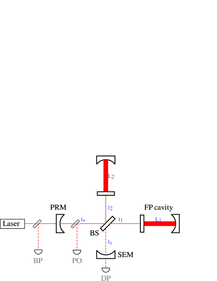
The optical configuration of the RSE interferometer is shown in Figure 1. The interferometric part consists of two input test masses and a beam splitter (BS). An input test mass and an end test mass form an FP cavity which plays an important role in the gravitational-wave signal enhancement. Additionally, the interferometer also has a PRM at the bright port (BP) footnote1 and a signal extraction mirror (SEM) at the dark port (DP).
Since the arm cavities have a high finesse (which indicates how many round trips light travels in a cavity) in the RSE configuration, the gravitational-wave signals are enhanced accordingly. However, the signals are over-circulated and they are canceled in the arm cavity owing to the phase changes of the gravitational wave signals. The SEM plays an important role in circumventing this problem. The signal extraction cavity (SEC) lowers the the effective finesse for the gravitational-wave signals and they escape from the cavities before over-circulation. On the other hand, the entire carrier light returns to the BP, so the SEC does not affect the power in the arm cavities. Thus the sensitivity will be improved.
The advantage of the RSE configuration is that the thermal problems can be circumvented being compared with an optical configuration of FP MI with a power-recycling cavity (PRC), which has the same sensitivity. The light power at the beam splitter or at the PRC is lower in the RSE case than in the FP MI case with a PRC. Especially for the LCGT, the mirrors will be kept at a super cryogenic temperature, thus it is necessary that the heat produced by the laser light absorption in the bulk of the input test masses is released through the suspension systems. If the heat is too high, the suspension systems cannot be refrigerated. Furthermore, even if the beam splitter and the PRM are not cooled, the thermal lens effect could cause. It would disrupt the mode matching of the light field and decrease the power in the arm cavities, possible leading to a worse shot noise limit.
To operate the interferometer as the gravitational-wave detector, all the mirrors have to be controlled at the proper positions so that the cavities are on resonance for the light fields. The longitudinal signals should be sent to the mirrors to control their positions. For the RSE interferometer, as shown in Fig. 1, there are five degrees of freedom to control; the arm-length common mode , the differential mode , the PRC length , the MI differential length , and the SEC length . The exact definitions of these lengths are shown in table 1.
and signals are extracted relatively independently since the phase sensitivities are enhanced by its stored light fields in the high finesse arm cavities. The difficulty is to extract the three signals of the central part of the RSE. If there is no cross talk between these signals, only one signal component can be sent and fed back to one degree of freedom most appropriately. In this ideal control condition, the system will be very robust. However, in most of the control schemes currently used or planned for use, these three signals are mixed with the others.
| Description | Symbol | Length |
|---|---|---|
| Common arm cavity | ||
| Differential arm cavity | ||
| PRC | ||
| Differential MI | ||
| SEC |
III Coupled - reflected method
III.1 Definition of coupled - reflected method
Our scheme, critically coupled - reflected method (coupled - reflected method for short) employs two sets of rf sidebands which do not enter the arm cavities to prevent the admixture of the arm length signals ( and ) and the other signals ( and ). In the conventional way, and signals are extracted by beating between the carrier light and PM sidebands at the BP and DP, respectively. To obtain and signals, the two sets of sidebands are double-demodulated at the PO. This technique requires that one of the two sidebands is phase-modulated whereas the other sideband is amplitude-modulated to be a local field against the PM field on the double demodulation scheme. The resonant conditions of the two sets of sidebands are;
-
(i) The PM sidebands reach the SEM by the critical coupling condition to carry information of the SEC effectively low . The PM fields are resonant inside the PRC and the SEC.
-
(ii) The AM sidebands are reflected completely by the MI so as not to carry any information of the SEC length. This condition can prevent a complex mixture between and .
-
(iii) The AM sideband is an applied so-called delocation scheme. Delocation is macroscopic detuning of AM sidebands by a slight change in the PRM position sato1 . The length-sensing matrix can be diagonalized by this delocation scheme.
The pair of sideband frequencies have to be determined to satisfy conditions (i) and (ii). To make the issue less complicated, let us introduce a view of the RSE interferometer as a coupled cavity system. The central part of the RSE interferometer can be modeled by a coupled cavity which contains three mirrors (see figure 2).
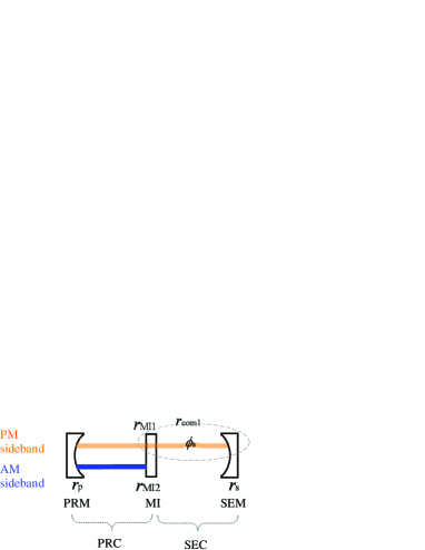
The reflectivity of the middle compound mirror (which corresponds to the MI), , can be determined by choosing the MI asymmetry length, , and the sideband frequency, ;
| (1) | ||||
| (2) |
where for the PM and AM sidebands respectively. The reflectivities of the arm cavities are assumed since neither of the sidebands go into the cavities.
We shall consider that the middle mirror and the SEM make another compound mirror again. The reflectivity of the new compound mirror is
| (3) |
where is the round trip phase between the middle mirror and the SEM.
-
(i) To determine the PM sideband frequency,
PM sidebands satisfy the critical coupling condition. In general, critical coupling is achieved when the input and end mirror have the same reflectivity and the laser lights are resonant in the cavity. The laser fields pass through the cavity without returning to the input port. To apply this condition for to the RSE interferometer, the PRM and the compound mirror which consists of the MI and SEM have the same reflectivity. Therefore, the reflectivity of the compound mirror satisfies,
(4) should be resonant in the SEC, . Substituting these conditions into Eq. (3), we get
(5) To realize the resonant condition in the PRC, should also satisfy
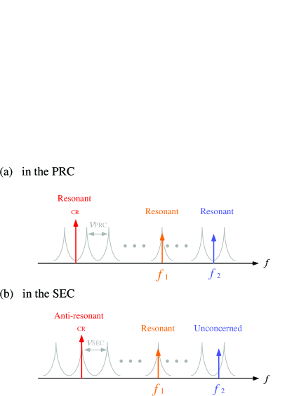
(6) where is the free spectral range (FSR) of the PRC, which is and is an arbitrary integer. This is because the sign of the carrier field is inverted by coming back from the two arm cavities, and they are resonant in the PRC when the PRC length is the anti-resonant condition for the carrier light. See, Fig. 3 (a). In a similar way, also satisfies
(7) where is the FSR of the SEC and is an arbitrary integer. As is shown in Fig. 3 (b), the SEC cavity length is set as the resonant for the carrier light. With this condition, the carrier light is virtually anti-resonant in the SEC because the carrier light comes back from the arm cavities.
-
(ii) To determine the AM sideband frequency,
To make the AM sidebands be reflected by the MI, Here, we supposed to make as low as possible. Therefore the AM sideband frequency satisfies
(8) In addition, also satisfies
(9) to be resonant in the PRC. is an arbitrary integer. This is because the sign of the AM sideband fields are inverted by .
Practically, when we design a interferometer, a so-called mode cleaner between the modulators and the interferometer will be necessary to eliminate the higher order Gaussian modes of the laser light. In order both sets of sidebands and the carrier light to transmit through the mode cleaner, the values of and should be integer multiples of the FSR of the mode cleaner cavity. However, under this additional condition, and cannot satisfy Eq. (6) and Eq. (9) at the same time. Therefore, in practical ways, we may use the values which satisfy the above conditions approximately and do not disturb the optical conditions.
This is one challenge of this method. The suitable optical parameters are discrete and not flexible for the changes of interferometer design because the parameters such as mirror reflectivities, the asymmetry length of MI and sideband frequencies depend on the optical design.
III.2 Features of Coupled-reflected method
One of the advantage of the coupled-reflected method is that short asymmetry length can be achieved. We can choose any asymmetry length as long as the frequency of AM sidebands satisfies Eq. (8). There are two advantages of short asymmetry length: easier mode matching and fewer phase noises. The effort of mode matching is easier when the inline and perpendicular path are identical. And also fewer laser phase noises are expected. The phase noises can be canceled at the DP when the inline and the perpendicular path has approximately the same length.
However, as a difficulty, the frequency tends to be high due to a very short asymmetry length, though the AM sideband is not the local oscillator for the gravitational waves. For example, these parameters assume that the asymmetry length is 0.824m and MHz in our simulation for LCGT (see Table 2).
The second benefit of the coupled-reflected method is that the clean signals can be acquired at the DP. In general, and should be isolated from and signals as much as possible, because and may include the gravitational wave signals and the two signals cannot be separately extracted in principle. The coupled-reflected method allows the signals without admixture of and because there are no AM sidebands in the SEC owing to the condition of .
Another major advantage of the coupled-reflected method is that the delocation technique can diagonalize the sensing matrix optically. When one of the , and signals is extracted, two kinds of demodulation phases can be chosen so that one desired signal is maximized, or an undesired signal is minimized. The , and signals are superposing in the demodulation-phase domain and cannot be extracted individually. Especially the and signals have the exact same dependencies on the demodulation phases. The delocation scheme can avoid this degeneracy. The delocation is a macroscopic detuning for the AM sidebands by changing the position of the PRM. The off-resonant AM fields can change the optimum double-demodulation phases for the three signals. The appropriate delocation amount realizes that one desired signal can be extracted while the undesired signals are zero on a pair of appropriate delocation phases. Therefore, the exact diagonalization of the sensing matrix is possible when optimum demodulation phases are chosen. Although the PRM position change affects the resonant condition of the PM sideband field in the PRC as well as the AM sidebands, the PM sidebands are only slightly off resonant since the delocation phase for the PM sidebands are small. This is because the delocation phase is proportional to the sideband frequencies and is much smaller than . See Eq. (18) in Section V.
The delocation technique is seem to decrease about 40% of signal compared with no delocation. This is because they are displaced from its resonant point and the power of AM sideband fields is reduced in the PRC.
IV Relation to other schemes
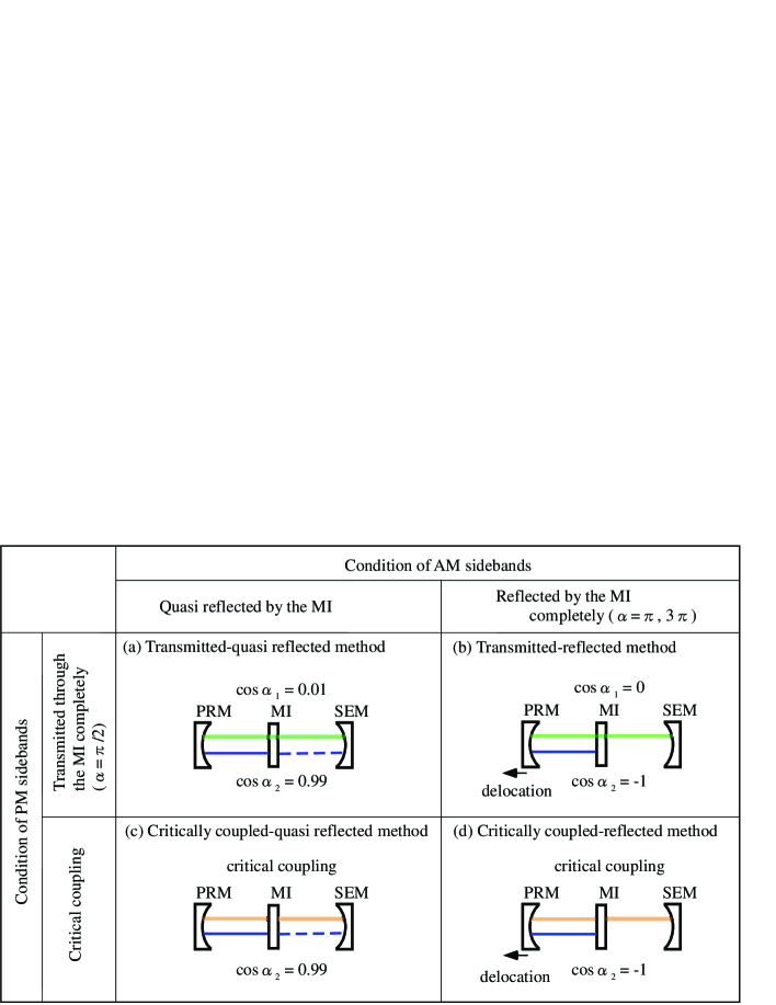
The coupled-reflected method was derived from three control schemes for the RSE interferometer which has already been discussed, or has been tested by prototype interferometers. The schemes can be categorized from the viewpoint of the sideband options. Depicted in Fig. 4, each set of sidebands has two options: for PM sidebands, the critically coupled or the complete transmission trough the MI; for AM sidebands, the complete reflection or the quasi-reflection by the MI. The combination of these options derives four schemes, the transmitted-quasi reflected method, the critically coupled-quasi reflected method, the transmitted-reflected method, and the critically coupled-reflected method. The critically coupled-reflected method was inspired as the fourth panel of the table shown in Fig. 4 (d).
The transmitted-quasi reflected method was developed by the LIGO group as a default method for Advanced LIGO adLIGO2 . As is shown in Fig. 4 (a), almost all of the PM sidebands transmit the MI. The frequency of the PM sidebands which satisfies is adopted for this method. On the other hand, a great part of the AM sidebands is reflected by the MI. The PM sidebands resonate both in the PRC and in the SEC, and the AM sidebands resonate only in the PRC. It is noted that the original scheme was not exactly the same as the transmitted-quasi reflected method since it was for a detuned RSE interferometer footnote2 .
The transmitted-reflected method has been developed by Sato as the control scheme for LCGT sato1 . As is shown in Fig. 4 (b), the PM sidebands pass through the MI completely and all the AM sidebands are reflected by the MI. The MI asymmetry length and the sideband frequencies satisfy , footnote so that the sideband conditions are met. The delocation technique is first introduced with this method.
The critically coupled-quasi reflected method has already been tested by Somiya low . As is shown in Fig. 4 (c), the PM sidebands are critically coupled and the AM sidebands slightly reach the SEM. The critical coupling condition was first introduced with a method to maximize signals by this method.
Comparing these four methods, one can find the coupled - reflected method inherits the advantages of other methods: A short asymmetry length of MI can be available inheriting the advantage of the critically coupled - quasi reflected method; no cross-talk between and in the signals at the DP inherits the advantage of the transmitted - reflected method; the diagonalized length sensing matrix by the delocation technique inherits the advantage of the transmitted - reflected method as well. In the next section, the analytical expressions and the numerical simulation results of the coupled - reflected method will be shown.
V Control signals and simulation result
The transfer function of light fields from the input to an arbitrary port is expressed as
| (10) |
where is the light field of the incident beam and is the light field at the port. contains the carrier component and two sets of upper () and lower () sideband components which are generated by the EOMs. The transfer function at the PO is
| (11) |
where for the PM and AM sidebands, respectively and is the round trip phase in the PRC. is the reflectivity of the compound cavity which includes the MI, FP arms and SEC for the PM and AM sidebands, respectively;
| (12) |
where is the average round trip phase of and and is the compound reflectivity of the arm cavity for each sideband component.
The sensitivities of the double-demodulated signals at the PO, for are given as
| (13) |
where represents the transfer functions of upper (lower) PM sidebands and is the transfer functions of AM sidebands at the PO. and are the demodulation phases.
From Eq. (11) and (V), the sensitivities of for and are
| (14) | ||||
| (15) | ||||
| (16) |
where is a square root of the power recycling gain for each sideband;
| (17) |
| (18) |
These equations include the effect of the delocation. The sidebands undergo delocation phase shifts, , caused by the macroscopic length displacement, , from the resonant point of the PRC. The two sideband fields experience different phase shifts because their phase changes depend on both the sideband frequencies and the displacement length. The SEC does not experience any change by the delocation.
When the delocation is not applied, and both the sidebands resonate in the PRC, . Therefore the signals without the delocation are
| (19) | |||
| (20) | |||
| (21) |
Eq. (19) and Eq. (21) indicate that and are exactly overlapping on the plane. The demodulation phases for both and are to maximize the signals. Therefore, the two signals cannot be extracted separately by choosing any demodulation phases. On the other hand, the signal can be extracted at the maximal point, where the other two signals are zero. The contour plots for these signals are shown in Fig. 6.
When the delocation is applied, and are nonzero. These nonzero terms change the signal dependencies on and they can solve the signal degeneracy. Depicted in Fig. 6, only one signal can be extracted without mixing with others by choosing appropriate demodulation phases; for example, becomes maximum whereas is zero on a certain pair of demodulation phases with a suitable amount of delocation.
| Length sensing matrix | |||||||
|---|---|---|---|---|---|---|---|
| Port | |||||||
| PO | 0 | 1 | |||||
| DP | 0 | 1 | |||||
| PO | 178 | 49.0 | 1 | ||||
| DP | 0 | 136 | 1 | ||||
| PO | 178 | 141 | 1 | ||||
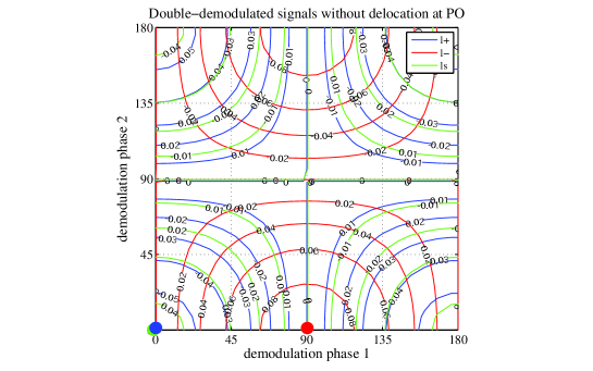
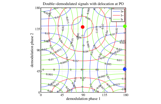
Table 2 shows the matrix of the length sensing signals. The demodulation phases are optimized to remove undesired signal components. E.g., signal is extracted at the BP by the single demodulation on a demodulation phase 0 whereas the other four signals are contained. This simulation was done by FINESSE FINESSE .
This well-diagonalized sensing matrix is supposed to provide the robust control because the optical diagonalization enables the servo loop to be simple. Even without the signal diagonalization, the interferometer can be controlled by using a signal matrix which has off-diagonal elements. But in that case, some additional servo systems are necessary to compensate for the off-diagonal elements. Such systems could add noise to the interferometer.
VI Summary
In summary, we have proposed a new length sensing control scheme for an RSE interferometer. The method has three significant advantages for robust control: a short asymmetry length of MI is available; the modulation sideband conditions enable the to have no cross-talk between and at the DP; and application of the delocation technique diagonalizes the length-sensing matrix.
VII acknowledgements
This research is supported partly by a Grant-in-Aid for Scientific Research on Priority Areas (415) of the Ministry of Education, Culture, Sports, Science and Technology, from Japan and also National Science Foundation cooperative agreement No. PHY-0107417 from U.S. funding.
References
- (1) M. Ando et al, Class. Quantum Grav. 22, S881 (2005)
- (2) F. Acernese et al, Class. Quantum Grav. 23, S635 (2006)
- (3) H. Lück et al., Class. Quantum Grav.21, S71 (2006)
- (4) A. Abramovici et al., Science 256, 325 (1992)
- (5) D. Sigg et al., Class. Quantum Grav. 23, S51 (2006)
- (6) K. Kuroda et al., Class. Quantum Grav. 23, S215 (2006)
- (7) A. Weinstein et al., Class. Quantum Grav. 19, S1575 (2002)
- (8) J. Mizuno, K. A. Strain, P. G. Nelson, J. M. Chen, R. Schilling, A. Rüdiger, W. Winkler, and K. Danzmann, Phys. Lett. A 175, 273 (1993)
- (9) These ports are traditionally called dark and bright, although they are not bright or dark for an RSE interferometer.
- (10) S. Sato, S. Kawamura, K. Kokeyama, F. Kawazoe, and K. Somiya, Phys. Rev. D 75, 082004 (2007)
- (11) O. Miyakawa et al., Phys. Rev. D 74, 022001 (2006)
- (12) Although the original method for Advanced LIGO was to use two sets of PM sidebands instead of AM, and the carrier field is detuned in the SEC, it is essentially equivalent to the transmitted-quasi reflected method.
- (13) K. Somiya, P. Beyersdorf, K. Arai, S. Sato, S. Kawamura, O. Miyakawa, F. Kawazoe, S. Sakata, A. Sekido, and N. Mio, Applied Optics 44, 16 ( 2005)
- (14) When , the critical coupling condition for PM sidebands is satisfied in this method as well.
-
(15)
http://www.rzg.mpg.de/~adf/