Coherent control of nanomagnet dynamics via ultrafast spin torque pulses.
pacs:
72.25.Ba,73.63.-b,75.75.+aThe magnetization orientation of a nanoscale ferromagnet can be manipulated using an electric current via the spin transfer effect Slonczewski (1996, 1999); Berger (1996, 1978): spin angular momentum is transferred from the conduction to the localized electrons, exerting an effective torque on the ferromagnet Katine et al. (2000); Sun (1999); Tsoi et al. (1998); Myers et al. (1999). Time domain measurements of nanopillar devices at low temperatures have directly shown that magnetization dynamics and reversal occur coherently over a timescale of nanoseconds Krivorotov et al. (2005). By adjusting the shape of a spin torque waveform over a timescale comparable to the free precession period (100-400 ps), control of the magnetization dynamics in nanopillar devices should be possible Rivkin and Ketterson (2006); Thomas et al. (2006, 2007). Here we report coherent control of the free layer magnetization in nanopillar devices using a pair of current pulses as narrow as 30 ps with adjustable amplitudes and delay. We show that the switching probability can be tuned over a broad range by timing the current pulses with the underlying free-precession orbits, and that the magnetization evolution remains coherent for more than 1 ns even at room temperature. Furthermore, we can selectively induce transitions along free-precession orbits and thereby manipulate the free magnetic moment motion. In contrast with previous measurements where the spin torque is applied throughout a large fraction of a precession cycleTulapurkar et al. (2004); Kaka et al. (2005); Schneider et al. (2007); Devolder et al. (2007, 2008), in our experiments the magnetization evolves through free-precession except for short time intervals when it is driven by the spin torque. We expect this technique will be adopted for further elucidating the dynamics and dissipation processes in nanomagnets, and will provide an alternative for spin torque driven spintronic devices, such as resonantly pumping microwave oscillators Rippard et al. (2004); Kaka et al. (2005), and ultimately, for efficient reversal of magnetic memory bits in nanoscale magnetic random access memory (MRAM).
We study spin transfer nanopillar devices patterned into 100nm ellipses with different aspect ratios (inset of Fig. 1a) at room temperature and 77 K. Antiferromagnetic dipolar field coupling between the thick layer (polarizer) and the “free” layer is canceled by biasing the devices with an easy axis magnetic field 800 Oe. The “free” layer can be switched between low resistance (parallel, ) and high resistance (anti-parallel, ) states via a spin-transfer torque from an applied dc current. A simple shaped waveform, consisting of two current pulses with equal polarity, comparable amplitude, and separated by a time delay (inset of Fig. 1b), is used to induce and control nanomagnet dynamics, while the final state of the multilayer is probed by measuring its steady state resistance. In our devices the free precession period 300 ps is much larger than the current pulse width 30 ps FWHM, but comparable to the inter-pulse delay 0 ns 2 ns. A femtosecond mode-locked laser in single-shot mode is used to generate a pair of optical pulses which are converted to electrical pulses using a LT-GaAs/Au photoconductive switch Auston (1984); Smith et al. (1989). A 40 GHz bias tee is used to inject both the current pulses that induce magnetization dynamics and the ac/dc currents used to measure the resistance and reset the device. Reflection measurements show that typical room temperature pulsewidths at the device are 30 ps, but due to cryostat bandwidth limitations the typical pulsewidths are 58 ps at 77 K. At nonzero temperatures thermal excitation of the “free” layer magnetization () affects its dynamical evolution. However, reproducibility in nanomagnet switching can be increased by applying transverse fields Devolder et al. (2007) or through inter-layer coupling Krivorotov et al. (2005). Throughout our measurements we apply in-plane transverse fields 200 Oe to shift the stable points of away from the easy axis (inset of Fig. 1a).
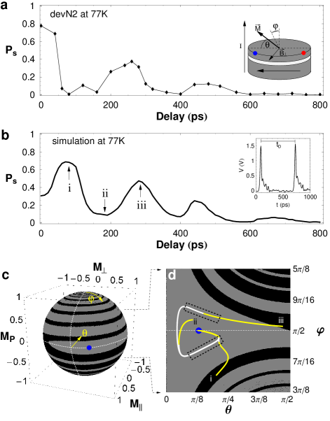
The switching probability as a function of inter-pulse delay for equal amplitude pulses at 77 K is shown in Fig. 1a. Large modulation of with delay implies coherent dynamics, since incoherent dynamics would lead to a delay-independent switching probability (with the single-pulse switching probability). To understand the origin of these oscillations, we model the time evolution of the magnetization of a single domain nanomagnet driven by a perpendicular spin current (inset of Fig. 1a), by using a modified Landau-Lifshitz-Gilbert equation which includes the Slonczewski spin torque term Slonczewski (1999); Sun (2000). We assume that the magnetization of the polarizer is fixed, and consider the effect of nonzero temperatures only on the distribution of initial conditions but not on the evolution of , which is assumed to be completely deterministic. is described by the angles and (inset of Fig. 1a)Sun (2000), and has fixed points at , with the easy axis anisotropy field. The phase portrait of in the absence of spin torque is shown in Fig. 1cBazaliy et al. (2004). The black and gray regions, which are the basins of attraction for the red and blue minimum energy points, are wrapped around each other, emphasizing the final state’s large sensitivity to fluctuations in initial conditions (i.e. thermal effects).
Simulations of the delay dependence of for a pair of pulses with equal amplitude at 77 K (Fig. 1b) show oscillations with delay that agree qualitatively with our observations (Fig. 1a). Typical trajectories at consecutive maxima and minima of , regions labeled i, ii, and iii, in Fig. 1b are shown in Fig.1d, where the section of the phase portrait shown in Fig. 1c has been stretched into a plane. The initial condition and first pulse (in yellow) are equivalent for all trajectories, but the second pulse (also in yellow) is applied at different times (90 ps, 190 ps, and 280 ps). The free evolution between the two pulses is shown in white. We observe that there are two regions (dashed boxes in Fig. 1d) where the second spin torque pulse can more effectively induce basin boundary crossing and lead to magnetization reversal. As indicated by trajectory ii, a second pulse applied outside of the marked regions can even push closer to the blue fixed point, effectively cancelling the effect of the first pulse. Therefore, when a pulse with a width larger than the free precession period is used for magnetization switching, partial cancellation of the spin torque can occur, decreasing the switching probability.
We observe that the clear oscillations and strong modulation of present in device N2 at 77 K (Fig. 1a) disappear at room temperature (Fig. 2a). Type “N” devices, with dc switching currents 0.4 mA, have a small stability factor (with the energy barrier between and states), and thus are more sensitive to thermal effects. At room temperature such devices typically show decay in with increasing delay, and small amplitude oscillations. On the other hand, extended bottom layer (type “E”) devices, with switching currents 2 mA and therefore higher thermal stability, typically show clear large amplitude oscillations in both at 77 K (Fig. 2b) and room temperature (Fig. 2c). Fourier analysis of the oscillations of device E1 at 77 K shows a fundamental period of 120 ps (=8.3GHz) and a much smaller 2 harmonic. Since the precession period is twice the period of the oscillations, for type “E” devices 240 ps. At room temperature the switching probability of device E2 can be tuned between 4 and 93 by only adjusting the delay between pulses. The enhancement in the switching probability from 60 at zero delay (single pulse) to 94 at 120 ps delay (Fig. 2c) has been measured while keeping the amplitude of the pulses constant. However, if the total energy delivered by the pulses is kept constant, a more dramatic enhancement in from 10 to 70 at intermediate pulse amplitudes and from 40 to 95 at larger pulse amplitudes is observed. Therefore, multiple current pulses timed with the underlying coherent dynamics require less total energy than a single pulse to reproducibly switch spin transfer devices.

We also measured the switching probability as a function of the amplitude of a pair of pulses while keeping their delay (185 ps) and relative amplitude () constant (Fig. 3a). initially increases with increasing pulse amplitude, but after 15 mA it decreases from 80 to 55 before finally increasing to 100 at 23 mA. This counterintuitive result that increasing the spin torque leads to a decrease in the switching probability is fully consistent with coherent precession and is predicted by our simulations (Fig. 3b). This agreement demonstrates that in our system the macro-spin model captures the essence of nanomagnet dynamics. Typical magnetization trajectories at the three labeled regions of Fig. 3b are shown in Fig. 3c. As the amplitude of the pair of pulses is increased from region I to region II (Fig. 3b), the state of at the end of the second pulse moves from the black basin to a higher energy gray basin region, therefore decreasing (Fig. 3c). As the amplitude of the pulses is increased further to region III in Fig. 3b, the first pulse produces enough spin torque to switch (Fig. 3c). Thus it is possible to move the magnetization into larger angle, higher energy orbits by applying multiple short current pulses with controlled amplitudes and delays.
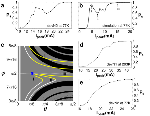
In contrast to previous reports Tulapurkar et al. (2004); Kaka et al. (2005); Schneider et al. (2007) where single pulses with 100 ps were required to achieve large , we demonstrate 100 with single 30 ps pulses at room temperature (Figs. 3d,e). Furthermore, for devices with dc switching currents comparable to those previously reported Kaka et al. (2005); Schneider et al. (2007) we achieve 100 with pulse amplitudes two times smaller than expected from the assumption of pulsewidth and amplitude being inversely proportional Koch et al. (2004); Li and Zhang (2003). These results are supported by macrospin simulations which indicate that the pulsewidth-current product required for 95 decreases by more than a factor of two when . Therefore, ultrashort current pulses apply spin torque more efficiently, increasing the probability of magnetization switching. Depending on field bias, temperature, and device anisotropy, can show either steppedDevolder et al. (2007) (Fig. 3d) or smoothSchneider et al. (2007); Kaka et al. (2005) (Fig. 3e), but always monotonic increase with increasing pulse amplitude. The stepped increase in is predicted by our simulations and was previously observed when increasing the pulse width Devolder et al. (2007). The steps are caused by the underlying free precession orbits, which play an essential role at short timescales, where the switching process is driven, instead of thermally-assisted. Thus, the free precession orbits provide a map for tailoring the amplitudes and timing of a series of short pulses in order to control the magnetization evolution.
As long as the motion remains coherent until the arrival of the last pulse, a series of short current pulses can be used to manipulate the free layer into a desired free-precession orbit, that is, to coherently control the magnetization. Our technique not only provides a proof of principle for such pulsed magnetization control, but also demonstrates coherent magnetic moment dynamics even at room temperature, and provides an alternative for high probability low power device switching. Using current pulses much shorter than the free-precession period is critical for controlling the magnetization motion. Our technique can be used to study the switching process in magnetic tunnel junctions, where a quiet “incubation” period that precedes magnetization switching has been observed Devolder et al. (2008), as well as to probe coherence and damping in out-of-plane nanopillar devices. Potential applications of our approach also include nano-oscillators Rippard et al. (2004); Kaka et al. (2005) which could be resonantly pumped for generating tunable microwaves over a broad GHz range.
We acknowledge helpful discussions with Yaroslaw Bazaliy. This work was funded by Seagate Research.
References
- Slonczewski (1996) J. C. Slonczewski, Journal of Magnetism and Magnetic Materials 159, L1 (1996).
- Slonczewski (1999) J. C. Slonczewski, Journal of Magnetism and Magnetic Materials 195, 261 (1999).
- Berger (1996) L. Berger, Phys. Rev. B 54, 9353 (1996).
- Berger (1978) L. Berger, Journal of Applied Physics 49, 2156 (1978).
- Katine et al. (2000) J. A. Katine, F. J. Albert, R. A. Buhrman, E. B. Myers, and D. C. Ralph, Phys. Rev. Lett. 84, 3149 (2000).
- Sun (1999) J. Z. Sun, Journal of Magnetism and Magnetic Materials 202, 157 (1999).
- Tsoi et al. (1998) M. Tsoi, A. G. M. Jansen, J. Bass, W.-C. Chiang, M. Seck, V. Tsoi, and P. Wyder, Phys. Rev. Lett. 80, 4281 (1998).
- Myers et al. (1999) E. B. Myers, D. C. Ralph, J. A. Katine, R. N. Louie, and R. A. Buhrman, Science 285, 867 (1999).
- Krivorotov et al. (2005) I. N. Krivorotov, N. C. Emley, J. C. Sankey, S. I. Kiselev, D. C. Ralph, and R. A. Buhrman, Science 307, 228 (2005).
- Rivkin and Ketterson (2006) K. Rivkin and J. B. Ketterson, Applied Physics Letters 88, 192515 (pages 3) (2006).
- Thomas et al. (2006) L. Thomas, M. Hayashi, X. Jiang, R. Moriya, C. Rettner, and S. Parkin, Nature 443, 197 (2006).
- Thomas et al. (2007) L. Thomas, M. Hayashi, X. Jiang, R. Moriya, C. Rettner, and S. Parkin, Science 315, 1553 (2007).
- Tulapurkar et al. (2004) A. A. Tulapurkar, T. Devolder, K. Yagami, P. Crozat, C. Chappert, A. Fukushima, and Y. Suzuki, Applied Physics Letters 85, 5358 (2004).
- Kaka et al. (2005) S. Kaka, M. R. Pufall, W. H. Rippard, T. J. Silva, S. E. Russek, J. A. Katine, and M. Carey, Journal of Magnetism and Magnetic Materials 286, 375 (2005).
- Schneider et al. (2007) M. L. Schneider, M. R. Pufall, W. H. Rippard, S. E. Russek, and J. A. Katine, Applied Physics Letters 90, 092504 (pages 3) (2007).
- Devolder et al. (2007) T. Devolder, C. Chappert, J. A. Katine, M. J. Carey, and K. Ito, Physical Review B (Condensed Matter and Materials Physics) 75, 064402 (pages 5) (2007).
- Devolder et al. (2008) T. Devolder, J. Hayakawa, K. Ito, H. Takahashi, S. Ikeda, P. Crozat, N. Zerounian, J.-V. Kim, C. Chappert, and H. Ohno, Physical Review Letters 100, 057206 (pages 4) (2008).
- Rippard et al. (2004) W. H. Rippard, M. R. Pufall, S. Kaka, S. E. Russek, and T. J. Silva, Physical Review Letters 92, 027201 (pages 4) (2004).
- Kaka et al. (2005) S. Kaka, M. Pufall, W. Rippard, T. Silva, S. Russek, and J. Katine, Nature 437, 389 (2005).
- Auston (1984) D. H. Auston, in Picosecond Optoelectronic Devices, edited by C. H. Lee (Academic, Orlando, 1984), pp. 73–117.
- Smith et al. (1989) F. W. Smith, H. Q. Le, V. Diadiuk, M. A. Hollis, A. R. Calawa, S. Gupta, M. Frankel, D. R. Dykaar, G. A. Mourou, and T. Y. Hsiang, Applied Physics Letters 54, 890 (1989).
- Sun (2000) J. Z. Sun, Phys. Rev. B 62, 570 (2000).
- Bazaliy et al. (2004) Y. B. Bazaliy, B. A. Jones, and S.-C. Zhang, Phys. Rev. B 69, 094421 (2004).
- Koch et al. (2004) R. H. Koch, J. A. Katine, and J. Z. Sun, Physical Review Letters 92, 088302 (2004).
- Li and Zhang (2003) Z. Li and S. Zhang, Phys. Rev. B 68, 024404 (2003).