Viscous shear-banding in foam
Abstract
Shear banding is an important feature of flow in complex fluids. Essentially, shear bands refer to the coexistence of flowing and non-flowing regions in driven material. Understanding the possible sources of shear banding has important implications for a wide range of flow applications. In this regard, quasi-two dimensional flow offers a unique opportunity to study competing factors that result in shear bands. One proposal for interpretation and analysis is the competition between intrinsic dissipation and an external source of dissipation. In this paper, we report on the experimental observation of the transition between different classes of shear-bands that have been predicted to exist in cylindrical geometry as the result of this competition [R. J. Clancy, E. Janiaud, D. Weaire, and S. Hutzlet, Eur. J. Phys. E, 21, 123 (2006)].
pacs:
83.80.Iz,83.50.Ax,83.60.WcIt has long been assumed that flowing and non-flowing regions can exist in driven complex fluids, especially in situations in which the stress is inhomogeneous. This behavior is often discussed in the context of yield stress materials BOO ; Moller et al. (2006). These are materials for which a critical stress is required for flow to be generated. Naturally, in a situation in which the stress varies from values below to above the critical, or yield, stress, one will have coexistence of flow and no flow. More recently, experimental studies have revealed a rich variety of shear-banding situations that do not conform to the “traditional” yield stress picture of shear bands Howell et al. (1999); Mueth et al. (2000); Losert et al. (2000); Coussot et al. (2002); Varnik et al. (2003); Kabla and Debregeas (2003); Lauridsen et al. (2004); Bécu et al. (2006); Gilbreth et al. (2006); Cohen et al. (2006); Janiaud et al. (2006); Clancy et al. (2006); Kabla and Debregeas (2007); Katgert et al. (2008).
One of the challenges to an increased understanding of shear banding in complex fluids is the large number of parameters and observed behavior. There is clearly no single cause of shear banding, and one must sort out the mechanisms for a range of different qualitative behaviors. Among the interesting range of behavior and models, we are going to highlight a few cases because of their relevance to the work discussed here and because they highlight the importance of distinguishing between qualitatively different types of shear banding. It is important to realize that these cases are not necessarily mutually exclusive. We will first consider issues related to the particulate nature of foams.
When considering shear banding in many complex fluids, one has to determine if a continuum model will be relevant or if one has to consider in detail the fact that the fluid consists of macroscopic “particles”. For example, foam is gas bubbles in the micron to millimeter range surrounded by liquid walls. Granular matter is similar size particles with gas. Experimentally, a transition to a “discrete” flow regime has been observed for extremely narrow shear bands on the order of 10 - 20 particles Rodts et al. (2005); Gilbreth et al. (2006). In this case, an interesting feature of the shear band is that the width becomes independent of the external driving velocity. This is fundamentally different behavior from continuum shear bands, where the width scales with the driving.
Another qualitative signature of different types of shear localization is the continuity, or lack there of, of the rate of strain at the transition from flow to no-flow. Continuous versus discontinuous transitions represent potentially different physics. This is supported by observations of a discontinuous transition in the rate of strain in a range of experimental systems Dennin (2008), including both three-dimensional systems and in quasi-two dimensional systems (bubble rafts) Lauridsen et al. (2004); Gilbreth et al. (2006). For simple cases, the origin of the discontinuity may be understood in terms of a competition between clustering of particles and the breakdown of cluster by shear Moller et al. (2008), but a complete theoretical understanding of mechanism for selecting between continuous and discontinuous transitions is still lacking.
Another qualitative feature of shear bands, especially in foams, is the fact that the velocity localization is often correlated with the localization of other dynamical features in the system. For example, flow in foams is dominated by local rearrangements of the bubbles (T1 events). The degree of correlation between velocity and T1 localization, and the possible role of T1 events as a source of shear localization, are an important feature of shear bands. Models have suggested that shear bands can result when local stress inhomogeneities are long lived and produce spatio-temporal correlations in the occurrence of plastic events in the flow (often associated with T1 events) Kabla et al. (2007). This tends to result only in continuous shear bands, so it serves as an alternative model to ones that describe discontinuous transitions. More recently, a useful direction for exploring the role of T1 events in focusing the flow has been proposed using surface evolver Wyn et al. (2008). This work has shed interesting light on the role of polydispersity in controlling the degree of localization.
As one starts to consider the various causes of shear localization, studies with quasi-two dimensional systems present an interesting option: role of external versus internal dissipation. This case has been of interest for a class of systems involving a single layer of bubbles. For these systems, there are three common configurations for the boundaries that are used to confine the bubbles to a plane. There is the classic bubble raft consisting of a single layer of bubbles at the air-water interface Bragg and Lomer (1949). This has recently been labelled the liquid-air (LA) geometry Vaz and Cox (2005), which is a useful distinction when making comparison with other common quasi-two dimensional geometries for foams. One can also confine the bubbles between glass plates in a Hele-Shaw geometry, referred to as glass-glass (GG). Finally, one can study a mixed system using bubble on a water surface with a top glass plate, the liquid-glass geometry (LG). Detail studies of the dynamics of individual bubbles in these geometries have helped our understanding of the differences between the systems Vaz and Cox (2005). Experimental studies in all three systems have established conclusively that dissipation between the bubbles and the boundaries can produce shear bands Wang et al. (2006); Kabla and Debregeas (2003); Katgert et al. (2008). Various theoretical models and simulations have pointed to the importance of the details of the competition between bubble-bubble dissipation and bubble-boundary dissipation Wang et al. (2006); Janiaud et al. (2006); Clancy et al. (2006); Katgert et al. (2008). A particularly interesting prediction exists for the case of the circular Couette geometry Clancy et al. (2006).
Circular Couette flow occurs for a material confined between two concentric cylinders. One can drive flow from either the outer or inner boundary. An important characteristic of Couette flow (in the absence of any external dissipation) is the fact that the stress decays as as one moves from the inner to the outer cylinder, independent of the driving. This establishes a natural situation for “classic” shear banding of a yield stress fluid, with flow occurring near the inner cylinder where the stress is the largest. An interesting feature of studies with bubble rafts is that this classic case is generally not observed. Instead, the shear bands are either discontinuous in the rate of strain or examples of discrete flow Lauridsen et al. (2004); Gilbreth et al. (2006). In this paper, we consider the case where external dissipation does exist, which modifies the spatial dependence of the internal stress, and explore the qualitative features of the shear banding.
Recently, theoretical studies of the impact of dissipation from an external boundary have predicted a range of striking behavior in Couette flow driven by the outer cylinder Clancy et al. (2006). For sufficiently high external dissipation, one should observe a series of transitions from a single shear band at the inner cylinder to shear bands at the inner and outer cylinder, and ultimately for high enough velocities of the outer cylinder, a shear band exclusively at the outer cylinder. This effect is possible because of the velocity dependent dissipation of the confining boundaries. In this paper, we report on an experimental confirmation of the transition from single shear bands to two shear bands in the flow of a bubble raft.
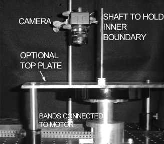
Our experimental setup utilizes bubble rafts in a Couette geometry. We are able to run both with and without a top boundary for the bubbles. For the bubble raft, we find that the flow is driven predominately from the rotating outer boundary, and the drag due to viscous dissipation between the bubbles and the aqueous subphase is relatively negligible. For our Couette system, there is a circular dish ( diameter, deep) mounted from below on a shaft. A corrugated disk, approximately in diameter was set concentrically within the circular dish. The shaft was supported by a set of bearings and connected using gears and driving bands to a variable speed stepper motor. The circular dish was filled with a homogeneous solution of high purity water, glycerol and miracle bubble solution in a 80:15:5 volume ratio. A stream of nitrogen gas was bubbled through the solution using a needle to generate a bubble raft in the spacing between the walls of the circular dish and inner disk. The bubbles in this 2D foam are polydisperse, with a diameters ranging between 2 mm to 9 mm. The circular dish was rotated at different angular velocities in order to generate differing amounts of shear within the 2D foam. The bubble raft was imaged from above using a standard CCD camera and digital images were saved to a computer every for a total of 4000 images. A standard PIV technique was used to track the bubbles and compute the azimuthal velocity profile as a function of radial position. The velocity profiles were found to have converged over the observation period for all the angular velocities studied. An image of the apparatus is given in Fig. 1.
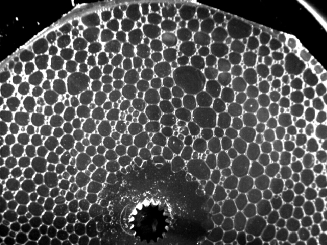
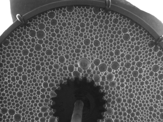
The experiment was run in two configurations: a) with the bubble raft open to the atmosphere and b) with a 1/4 inch thick, transparent polycarbonate sheet in contact with the bubbles on top. With the addition of the top plate, a relatively uniform viscous drag is generated between the bubbles and the top plate. This drag force is velocity dependent. In both cases, the bubbles at the inner barrier are held stationary at the corrugated barrier. In case (a), slip at the outer barrier is eliminated by the insertion of 2 mm thick protrusions along the outer wall. In case (b), the viscous drag between the top plate and the foam was stronger than that with the outer wall, and we were unable to eliminate slip between the outer wall and the last layer of foam. In this case, a corrugated barrier was found to be insufficient to hold the bubbles in place, instead causing artifacts by frothing of the bubble raft even at low angular speeds. Therefore, in case (b), the outer wall was moved at a higher angular velocity than the bubbles in contact with it. The viscous drag between the bubbles and the liquid subphase is not a significant contribution to the dynamics of the flow in comparison to that of the top plate and the outer wall. This is verified by checking that the bubbles do not undergo any rotational motion when only in contact with the inner barrier and the rotating subphase (without touching the outer wall, or the upper plate). A limitation in our experiment is that at high angular velocities with a top plate, a frothy solution was formed at the outer barrier that changed the dispersity of the foam from its initial condition. In the data presented in this paper, we limit our angular velocities to a regime where the froth formation does not occur significantly. The qualitative difference in the flow profile was not seen to be strongly influenced by the polydispersity of the bubble rafts used.
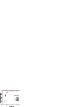
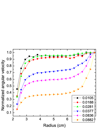
The average velocity profile of the bubbles in our experiments have a circular symmetry reflecting the geometry of the shear. The average radial velocity is zero during steady shear as expected from the continuity equation in this radially confined system. We therefore focus on the azimuthal velocity () as a function of radial position at different driving rates imposed. When rotating the outer boundary, a region of “no-flow” corresponds to rigid body rotation, , where is the angular rotation rate of the outer boundary. Therefore, to simplify the interpretation of the results, we present reduced velocities given by , and is a region of “no flow”. In Fig. 2, we plot for the case without a top. It should be noted that instead of using for the outer cylinder, we use of the layer of bubbles adjacent to the outer cylinder. In the case of no top, these two numbers are equivalent because there is no slip. However, the presence of a top introduces slip, and for consistency we found it best to normalize by the first layer of bubbles.
The measurements of in the absence of a confining top plate provide a comparison with previous measurements using a different Couette apparatus. The main feature of these measurements is the existence of a shear band at the inner cylinder for all rotation rates. However, it is worth pointing out that in this regime, the width of the the shear bands is independent of the rotation rate of the outer cylinder.
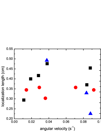
If one defines critical radius for the shear band by the location at which the flow is indistinguishable from rigid body rotation, one observes a critical radius on the order of 10 of the smallest bubble diameter. Alternatively, one can fit the velocity profile in the shear band region to an exponential, and define a decay length as in Ref. Clancy et al. (2006). The results from this fit are show in Fig. 4. As with the critical radius, the decay lengths are independent of the angular velocity of the outer layer of bubbles. Previous studies of bubble rafts without a top have identified a flow regime for which the critical radius is independent of the rotation rate of the outer barrier Gilbreth et al. (2006). This occurs for rates of strain below a critical value on the order of , and it is referred to as the discrete regime. Similar behavior has been observed in three-dimensional foam systems Rodts et al. (2005). As the angular velocity of the outer cylinder is on the order of the rate of strain, the observation of a rate of strain independent decay length is consistent with previous studies.
With the addition of the top plate, the profiles at low rates of strain are similar to those without a top in that the flow is localized at the inner cylinder. However, if one considers the decay length for the shear band, one observes a dependence on the outer cylinder velocity. (As with the case without a top, an exponential fit was used to compute the decay length.) As the velocity increases, the decay length appears to saturate. This suggests that the dissipation from the top qualitatively changes the behavior of the system and plays an important role. For example, this behavior is completely different from what is observed in the discrete regime, and suggests a continuum model, such as the one reported on in Ref. Clancy et al. (2006), may be valid. Quantitative comparisons to the predictions reported in Ref. Clancy et al. (2006) are severely limited, in part due to the fact that the magnitude of the dissipation between the plate and the bubbles is unknown, and that the model is relatively simplified. However, it is worth pointing out that the decay length for the case of rotating the inner barrier exhibits similar behavior in the model as observed in our experiments (see Fig. 8 of Ref. Clancy et al. (2006)). However, this comparison is only indirect, as we rotate the outer barrier.
As the velocity of the outer barrier is increased, we observe the behavior predicted in Ref. Clancy et al. (2006). In addition to flow at the inner barrier, we observe flow at the outer wall. The region in between these two zones moves as a rotating rigid body. This results in a shear band at both boundaries. We were unable to sample higher shear rates due to limitations of our apparatus, and have not been able to observe the prediction of a single shear band at the outer wall. As with the shear bands at the inner cylinder, we fit the shear bands at the outer wall to an exponential profile and plot the decay lengths in Fig. 4. It is interesting to note that the trend for the outer barrier decay lengths is opposite that of the one at the inner barrier. Though not reported on in Ref. Clancy et al. (2006), this is a useful test of the model that can be checked in detail in the future, and one can make a qualitative argument in the context of the model proposed in Ref. Clancy et al. (2006).
As suggested by Clancy et al. Clancy et al. (2006), the viscous damping between the top plate and the bubbles is one source of the formation of shear bands. In the regime where this dominates, because the drag increases with increasing velocity, there is a tendency for the shear bands to move radially outwards with increasing shear rates. This observation is seen to hold at both the inner as well as the outer shear bands and is quantified by the increase in decay length for the inner shear band and decreasing decay band for the outer shear band with an increase in the rotation rate. It is also useful to note that while the viscous drag increases with radial position, the stress increases with decreasing radial position. The plateau between the shear bands corresponds to a region where the viscous drag is balanced by the internal stresses within the bubble raft, resulting in a constant rotational velocity.
In summary, the observation of the dual shear bands represents agreement with the predictions of the theoretical model described in Ref. Clancy et al. (2006). For our system, the transition from a single shear band region at the inner boundary, to a dual shear band region at the inner and outer boundary occurs at a critical scaled azimuthal velocity for the outer row of bubbles of . In the context of Ref. Clancy et al. (2006), this provide insight into the dissipation due to the top plate. Our previous work has focused on two cases: bubble rafts with and without a top. For Couette flow without a top, we have observed two regimes Gilbreth et al. (2006): discontinuous transitions and a discrete regime. As discussed, the results for the flow without a top reported here are consistent with the discrete regime. As such, one does not expect the model discussed in Ref. Clancy et al. (2006) to be applicable. Surprisingly, with a top, our current results are consistent with experiments from a range of groups that have confined bubbles either between two glass plates or between a fluid and a glass plate. In all of these cases, exponential profiles for the velocity are observed Debrégeas et al. (2001); Wang et al. (2006); Katgert et al. (2008). The differences between these studies is the behavior of the width of the shear band as a function of the applied rotation rate. However, these differences in rate dependence can be explained in the context of the continuum model (see for example, Fig. 8 of Ref. Clancy et al. (2006) and Ref. Katgert et al. (2008) which extends the model of Clancy et al. (2006)).
Finally, the direct observation of a transition from a single shear band to a double shear band as a function of increasing velocity of bubbles for a bubble raft in a Couette geometry confirms the prediction of the model described in Ref. Clancy et al. (2006) that such behavior occurs in the presence of sufficient external drag on a foam system. Experimentally, the fact that this shear band occurs when a top plate is added confirms that confining boundaries in quasi-two dimensional foam systems provide substantial drag that must be understood and accounted for in theoretical models. Though it remains clear from other experiments that this mechanism will not explain all cases of shear-banding, these experiments provide strong evidence that it is an important mechanism in situations involving external drag. Some interesting future directions will be to look at the impact of polydispersity (as in Ref. Wyn et al. (2008)) and to explore in more detail the impact of velocity dependent drag forces in the regime in which discontinuous shear localization exists.
K. Krishan acknowledges financial support by ICAM. M. Dennin acknowledges the support of University of California, Irvine, through bridge funding.
References
- (1) R. B. Bird, R. C. Armstrong, and O. Hassage, Dynamics of Polymer Liquids (Wiley, New York, 1977) and C. Macosko, Rheology Principles, Measurements, and Applications (VCH Publishers, New York, 1994).
- Moller et al. (2006) P. C. F. Moller, J. Mewis, and D. Bonn, Soft Matter 2, 274 (2006).
- Bécu et al. (2006) L. Bécu, S. Manneville, and A. Colin, Phys. Rev. Lett. 96, 138302 (2006).
- Clancy et al. (2006) R. J. Clancy, E. Janiaud, D. Weaire, and S. Hutzler, European Journal of Physics E 21, 123 (2006).
- Cohen et al. (2006) I. Cohen, B. Davidovitch, A. B. Schofield, M. P. Brenner, and D. A. Weitz, Phys. Rev. Lett. 97, 215502 (2006).
- Coussot et al. (2002) P. Coussot, J. S. Raynaud, F. Bertrand, P. Moucheront, J. P. Guilbaud, H. T. Huynh, S. Jarny, and D. Lesueur, Phys. Rev. Lett. 88, 218301 (2002).
- Gilbreth et al. (2006) C. Gilbreth, S. Sullivan, and M. Dennin, Physical Review E 74, 051406 (2006).
- Howell et al. (1999) D. Howell, R. P. Behringer, and C. Veje, Phys. Rev. Lett. 82, 5241 (1999).
- Janiaud et al. (2006) E. Janiaud, D. Weaire, and S. Hutzler, Physical Review Letters 97, 038302 (2006).
- Kabla and Debregeas (2003) A. Kabla and G. Debregeas, Physical Review Letters 90, 258303 (2003).
- Kabla and Debregeas (2007) A. Kabla and G. Debregeas, Journal of Fluid Mechanics 587, 23 (2007).
- Katgert et al. (2008) G. Katgert, M. E. Möbius, and M. van Hecke, Phys. Rev. Lett. 101, 058301 (2008).
- Lauridsen et al. (2004) J. Lauridsen, G. Chanan, and M. Dennin, Phys. Rev. Lett. 93, 018303 (2004).
- Losert et al. (2000) W. Losert, L. Bocquet, T. C. Lubensky, and J. P. Gollub, Phys. Rev. Lett. 85, 1428 (2000).
- Mueth et al. (2000) D. M. Mueth, G. F. Debregeas, G. S. Karczmar, P. J. Eng, S. R. Nagel, and H. M. Jaeger, Nature 406, 385 (2000).
- Varnik et al. (2003) F. Varnik, L. Bocquet, J.-L. Barrat, and L. Berthier, Phys. Rev. Lett. 90, 095702 (2003).
- Rodts et al. (2005) S. Rodts, , J. C. Baudez, and P. Coussot, Europhysics Letters 69, 636 (2005).
- Dennin (2008) M. Dennin, J. Physics: Cond. Mat. 20, 283103 (2008).
- Moller et al. (2008) P. C. F. Moller, S. Rodts, M. A. J. Michels, and D. Bonn, Phys. Rev. E 77, 041507 (2008).
- Kabla et al. (2007) A. Kabla, J. Scheibert, and G. Debrégeas, J. Fluid Mech. 587, 45 (2007).
- Wyn et al. (2008) A. Wyn, I. T. Davies, and S. J. Cox, Euro. Phys. J. E 26, 81 (2008).
- Bragg and Lomer (1949) L. Bragg and W. M. Lomer, Proc. R. Soc. London, Ser. A 196, 171 (1949).
- Vaz and Cox (2005) M. F. Vaz and S. Cox, Phil. Mag. Lett. 85, 415 (2005).
- Wang et al. (2006) Y. Wang, K. Krishan, and M. Dennin, Physical Review E 73, 031401 (2006).
- Debrégeas et al. (2001) G. Debrégeas, H. Tabuteau, and J. M. di Meglio, Phys. Rev. Lett. 87, 178305 (2001).