]www.ima.umn.edu/ astein
The Micromechanics of Three Dimensional Collagen-I Gels
Abstract
We study the micromechanics of collagen-I gel with the goal of bridging the gap between theory and experiment in the study of biopolymer networks. Three-dimensional images of fluorescently labeled collagen are obtained by confocal microscopy and the network geometry is extracted using a 3d network skeletonization algorithm. Each fiber is modeled as a worm-like-chain that resists stretching and bending, and each cross-link is modeled as torsional spring. The stress-strain curves of networks at three different densities are compared to rheology measurements. The model shows good agreement with experiment, confirming that strain stiffening of collagen can be explained entirely by geometric realignment of the network, as opposed to entropic stiffening of individual fibers. The model also suggests that at small strains, cross-link deformation is the main contributer to network stiffness whereas at large strains, fiber stretching dominates. Since this modeling effort uses networks with realistic geometries, this analysis can ultimately serve as a tool for understanding how the mechanics of fibers and cross-links at the microscopic level produce the macroscopic properties of the network. While the focus of this paper is on the mechanics of collagen, we demonstrate a framework that can be applied to many biopolymer networks.
pacs:
Collagen is the most abundant animal protein Lodish et al. (1999) and its mechanics have been studied in great detail Fung (1993). It takes on many morphologies, including skin, tendons, ligaments, individual fibers, and gels. Of particular interest is the mechanics of collagen-I gels, shown in Figure 1a. These gels provide a relatively simple structure that can be noninvasively observed by confocal microscopy Stein et al. (2008) and used as a scaffold for growing artificial tissues Chandran and Barocas (2004), and as a 3d environment for studying cell motility Friedl et al. (1998) and tumor invasion Kaufman et al. (2005); Stein et al. (2007). A critical first step in understanding these systems is to develop a model for the collagen gel alone. In this paper we give a successful theoretical model of the micromechanics of realistic networks.
Collagen-I gels belong to a class of materials known as biopolymers. Other examples include actin, found in the cytoskeleton and fibrin, a component of blood clots. A common feature of biopolymer networks is their ability to strain stiffen by 2-3 orders of magnitude at large strains (Figure 1f). The cause of this strain stiffening is not well understood. Storm et al. Storm et al. (2005) attributed strain stiffening in all biopolymer networks to the pulling out of entropic modes of individual filaments. Their calculation required the assumption that deformations are affine. Later, Heussinger et al. Heussinger and Frey (2006); Heussinger et al. (2007) showed how one could deconstruct the network deformation into a set of floppy modes. They concluded that accounting for the non-affinity was necessary in describing the elastic properties of the network. Onck and colleagues Onck et al. (2005); Huisman et al. (2007) have proposed the alternative hypothesis that strain stiffening is due to the rearrangement of the fibers as the network is strained (Figures 1d and 1e). Resolving this debate has been difficult since almost all theoretical analysis has been on artificially generated networks. The few examples of quantitative comparisons to experiment in the literature Storm et al. (2005); Chandran and Barocas (2006); Stylianopoulos and Barocas (2007) are not able to quantitatively fit the full stress-strain response of the gel at varying densities using a single set of parameters.
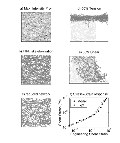
In this paper, we bridge the gap between model and experiment. Three dimensional images of fluorescently labeled collagen gels at different densities are imaged by confocal microscopy (Figure 1a) and the network geometry is extracted using a custom FIbeR Extraction (FIRE) algorithm (Figure 1b) Stein et al. (2008). The gel is modeled as a random network of cross-linked fibers, as described below, and the stress-strain response is compared to that measured by an AR-G2 rheometer. Good agreement between model and experiment is obtained by fitting a single parameter, the cross-link stiffness. The experiments are described in detail in Stein et al. (2008).
In the model for the collagen gel, each fiber is treated as a discrete worm-like-chain (WLC) Klapper and Qian (1998) which resists stretching and bending, and each cross-link is treated as a torsional spring, thus more stiff than a freely rotating pin joint but less stiff than a welded joint of fixed angle. The stretching modulus of an individual fiber is given by , where is the Young’s modulus and is the cross-sectional area. The Young’s modulus of a fiber in aqueous conditions has been estimated to be between 30-800 MPa Graham et al. (2006); Miyazaki and Hayashi (1999); van der Rijt et al. (2006) and we use a modulus of 50 MPa, which fits the data well and is also close to the value chosen by Stylianopoulous et al. (79MPa) to fit their model Stylianopoulos and Barocas (2007). It has been shown that a single fiber will stiffen by a factor of 2-4 when strained van der Rijt et al. (2006). We choose here to use a constant both to reduce the number of parameters in the model and to see if geometric reorientation of the network is enough to explain strain stiffening. Stylianopoulos and Barocas Stylianopoulos and Barocas (2007) also explored the bilinear and exponential constitutive relations for the individual fibers and observed only minor effects on the macroscopic network behavior. The radius of each fiber is nm Stein et al. (2008); Raub et al. (2007). The bending modulus of the fiber is given by pN-m2, where Yang et al. (2008). No cross-linking agent has been added to the gel and very little is known about the nature of the naturally formed collagen cross-links. We find that we can fit all the data by setting the torsional spring stiffness to pN-m. To compare to , we consider , where the mean cross-link spacing is given by m Stein et al. (2008). Thus, we find that . One possible reason for a larger could be an increase in fiber radius near the cross-links by a factor of 2, since bending stiffness scales by .
We assume that in the undeformed state of the network, there are no internal stresses. Thus the fibers have an innate curvature and the cross-links have an equilibrium angle equal to that in their initial configuration. We ignore entropic contributions to the fiber mechanics. While the geometric persistence length of these fibers has been measured to be 20 m Stein et al. (2008), the thermal persistence length is much longer cm. Furthermore, in the case that the strain stiffening is dominated by thermal compliance, one would expect to see a decrease in the yield strain with increasing concentration Head et al. (2003). Collagen gels, however, have been shown to have a constant yield strain of about 60% for a wide range of concentrations Roeder et al. (2002). Thus the total energy in the network for a given configuration is given below.
| (1) |
Here is the number of elements of type , which denotes stretching, bending, and cross-link, is the length of stretching element, and are the bending and cross-link angles respectively, and indicates the difference between the deformed and undeformed state.
To calculate the stress-strain relationship of our model network, we perform a series of 18 incremental strain steps by imposing a small deformation on one face, while holding the opposite face, fixed. We impose two types of deformations: tension (Figure 1d) and shear (Figure 1e). In a tensile deformation, we allow the vertices on and to move freely in directions perpendicular to the imposed strain to allow for perpendicular contraction that is seen to occur in these experiments Roeder et al. (2002); Krishnan et al. (2004). In experiments of this type, the distance between and is on the order of centimeters and the simulated network represents a small region near the center of a sample. In shear, we do not allow the boundary nodes on and to move freely. We compare the shear results to cone-plate rheometer experiments, where the shear faces are bound to the rheometer. Here, the distance between and is 109 m, and the simulated network is one fourth the length of the experimental sample between the boundaries. In both deformations, all other nodes, including those on the four remaining faces of the network, are free to move.
The minimum energy state of the network at an imposed strain is found using a conjugate gradient method developed by Hager and Zhang Hager and Zhang (2005). The stress required to hold the network in its current configuration is given by , where denotes the area of . The results shown in Figures 2 and 3 are averaged over all four extracted networks and over all 6 principle shear deformations in the sheared network and all 3 principle tensile directions in the stretched network.
The results from our shear cell experiments are given in Figures 2 and 3a. In addition, in Figure 3b, we also present the previously reported tensile modulus of large samples that are centimeters in length Roeder et al. (2002). Figure 2a shows a strain sweep from 0.5% to 100% shear strain in both the model and cone-plate rheometer experiments. At small strains, the stress-strain response is linear, as expected, and at larger shear strains, the stress-strain response appears cubic. In Figure 3a, we show that the small strain modulus scales by , where is the collagen density. At this time, it is not possible to verify the power law scaling in the model since only densities of 0.5, 1.2, and 1.4 were observed. The fluorescent labeling of the network changes the polymerization properties of the network, causing it to clump at higher densities. We use this scaling relationship to collapse the curves in Figure 2b. The close agreement between model and experiment indicates that strain stiffening due to the geometric rearrangement of the collagen fibers is enough to explain the strain stiffening seen in experiments.

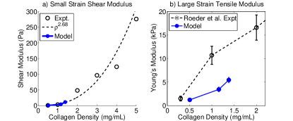
At large strains ( in tension, in shear), the stress-strain curve of the model becomes linear again, though with a much steeper slope. In Figure 3b, we compare the large strain tensile behavior of the model to the experiments of Roeder et al. Roeder et al. (2002). While our model underestimates their experimental measurement by a factor of 2.5, we find this to be reasonable since the two experiments used different collagen protocols. In particular, different buffers were used. In Figure 2, we also explore the case where , such that we have only a network of springs connected at freely rotating pin joints. At low strains, the network can be deformed without exerting any stress, but at strains higher than 25%, we see that this simplification adequately describes the gel.
A topic of investigation explored by many is the validity of the assumption that these networks deform affinely Onck et al. (2005); Heussinger and Frey (2007). For brevity, we state only that the deformations are highly nonaffine in these simulations, as evidenced by a visual inspection of Figure 1d and 1e where it is obvious that many fibers leave the volume defined by an affine deformation.
In summary, we have presented a microstructural model of a 3d biopolymer gel using a network geometry that is based on the true network architecture. It differs from previous work in that we use realistic network architectures that have been extracted using the FIRE algorithm. We specifically focus on the mechanics of collagen-I networks, but emphasize that this modeling approach is generalizable to other biopolymer networks. The model has three parameters: . The fiber radius and tensile modulus can be measured experimentally and the model uses realistic parameters. The cross-link torsional spring constant must be fit to the data and we used . Fitting this single parameter gives the right strain stiffening behavior for networks at three different densities at strains that vary from 0.5% to 50%. This result lends support to the hypothesis put forward by Onck et al. Onck et al. (2005) that strain stiffening in polymer networks, and particularly collagen-I gels, is governed by rearrangement of the gel.
Another finding of the model is that at strains greater than 25%, the stiffness of the gel is governed almost entirely by stretching of the fibers. This result is relevant for collagen because cells embedded in these gels are seen to produce deformations of this order of magnitude Pizzo et al. (2005). In modeling large systems of this type where the strains are large, it may be sufficient to treat each fiber as a spring rather than a WLC in order to reduce the computation time. This work also demonstrates that an understanding of the cross-link mechanics in these systems is critical to understanding their mechanical properties, as has been seen previously Wagner et al. (2006). In much of the theoretical work that has been done on random stick networks, the cross-links are treated either as freely rotating pin joints, or welded joints of fixed angle Head et al. (2003); Onck et al. (2005); Heussinger and Frey (2007). While these are sensible simplifying assumptions in developing a theory, they are not adequate for describing actual networks.
We note that this model has been designed to capture the short time scale ( 1 hr) behavior of the network, where it behaves as an elastic solid. Such behavior requires that the cross-links be relatively fixed Barocas et al. (1995). This simplified model provides a starting point in the development of a more complete model of collagen gel. Ultimately, a more sophisticated approach, such as that taken by Rodney et al. Rodney et al. (2005) will be necessary to capture the full dynamic behavior of the gel, where cross-links are allowed to slip and break.
Acknowledgments
The authors would like to thank V. Barocas, T. Stylianopoulos, E. A. Sander, E. Tuzel, H. Zhang, H. Othmer, T. Jackson, P. Smereka, R. Krasny, F. MacKintosh, A. Kabla, R. Lee, M. Dewberry, L. Kaufman and L. Jawerth, and for their discussions. This work is supported by NIH Bioengineering Research Partnership grant R01 CA085139-01A2 and the Institute for Mathematics and its Applications.
References
- Lodish et al. (1999) H. Lodish, A. Berk, S. L. Zipursky, P. Matsudaira, D. Baltimore, and J. Darnell, Molecular Cell Biology (W. H. Freeman and Company, 1999).
- Fung (1993) Y. C. Fung, Biomechanics: Mechanical Properties of Living Tissues (Springer, New York, 1993), 2nd ed.
- Stein et al. (2008) A. M. Stein, D. A. Vader, L. M. Jawerth, D. A. Weitz, and L. M. Sander, accepted by J. Microscopy (2008).
- Chandran and Barocas (2004) P. L. Chandran and V. H. Barocas, Journal of Biomechanical Engineering 126, 152 (2004).
- Friedl et al. (1998) P. Friedl, K. S. Zanker, and E.-B. Brocker, Microscopy Res. and Tech. 43, 369 (1998).
- Kaufman et al. (2005) L. J. Kaufman, C. P. Brangwynne, K. E. Kasza, E. Filippidi, V. D. Gordon, T. S. Deisboeck, and D. A. Weitz, Biophys. J. 89, 635 (2005).
- Stein et al. (2007) A. M. Stein, T. Demuth, D. Mobley, M. E. Berens, and L. M. Sander, Biophys. J. 92, 356 (2007).
- Storm et al. (2005) C. Storm, J. Patsore, F. MacKintosh, T. Lubensky, and P. Janmey, Nature 435, 191 (2005).
- Heussinger and Frey (2006) C. Heussinger and E. Frey, Phys. Rev. Lett. 96, 017802 (2006).
- Heussinger et al. (2007) C. Heussinger, B. Schaefer, and E. Frey, Phys. Rev. E 76, 031906 (2007).
- Onck et al. (2005) P. Onck, T. Koeman, T. van Dillen, and E. van der Giessen, Phys. Rev. Lett. 95, 178102 (2005).
- Huisman et al. (2007) E. M. Huisman, T. van Dillen, P. Onck, and E. van der Giessen, Phys. Rev. Lett. 99, 208103 (2007).
- Chandran and Barocas (2006) P. L. Chandran and V. H. Barocas, J. Biomech. Eng. 128, 259 (2006).
- Stylianopoulos and Barocas (2007) T. Stylianopoulos and V. H. Barocas, Comput. Methods Appl. Mech. Eng. 196, 2981 (2007).
- Klapper and Qian (1998) I. Klapper and H. Qian, Biophys. J. 74, 2504 (1998).
- Graham et al. (2006) J. S. Graham, A. N. Vomund, C. L. Phillips, and M. Grandbois, Exp. Cell Res. 299, 335 (2006).
- Miyazaki and Hayashi (1999) H. Miyazaki and K. Hayashi, Biomedical Microdevices 2, 151 (1999).
- van der Rijt et al. (2006) J. A. J. van der Rijt, K. O. van der Werf, M. L. Bennink, P. J. Dijkstra, and J. Feijen, Macromol. Biosci. 6, 697 (2006).
- Raub et al. (2007) C. B. Raub, V. Suresh, T. Krasieva, J. Lyubovitsky, J. D. Mih, A. J. Putnam, B. J. Tromberg, and S. C. George, Biophys. J. 92, 2212 (2007).
- Yang et al. (2008) L. Yang, K. O. van der Werf, B. F. Koopman, V. Subramaniam, M. L. Bennink, P. J. Dijkstra, and J. Feijen, Biophys. J. 94, 2204 (2008).
- Head et al. (2003) D. Head, A. J. Levine, and F. MacKintosh, Phys. Rev. E 68, 061907 (2003).
- Roeder et al. (2002) B. A. Roeder, K. Kokini, J. E. Sturgis, J. P. Robinson, and S. L. Voytik-Harbin, Journal of Biomechanical Engineering 124, 214 (2002).
- Krishnan et al. (2004) L. Krishnan, J. A. Weiss, M. D. Wessman, and J. B. Hoying, Tissue Engineering 10, 241 (2004).
- Hager and Zhang (2005) W. W. Hager and H. Zhang, SIAM J. Optim. 16, 170 (2005).
- Heussinger and Frey (2007) C. Heussinger and E. Frey, Phys. Rev. E 75, 011917 (2007).
- Pizzo et al. (2005) A. M. Pizzo, K. Kokini, L. C. Vaughn, B. Z. Waisner, and S. L. Voytik-Harbin, J. Appl. Physiol. 98, 1909 (2005).
- Wagner et al. (2006) B. Wagner, R. Tharmann, I. Haase, M. Fischer, and A. R. Bausch, Proc. Natl. Acad. Sci. USA 103, 13974 (2006).
- Barocas et al. (1995) V. H. Barocas, A. G. Moon, and R. T. Tranquillo, J. Biomech. Eng. 117, 161 (1995).
- Rodney et al. (2005) D. Rodney, M. Fivel, and R. Dendievel, Phys. Rev. Lett. 95, 108004 (2005).