Mirrorless Negative-index Parametric Micro-oscillator
Abstract
The feasibility and extraordinary properties of mirrorless parametric oscillations in strongly absorbing negative-index metamaterials are shown. They stem from the backwardness of electromagnetic waves inherent to this type of metamaterials.
pacs:
42.65.Yj, 78.67.Pt, 42.50.GyOptical negative-index (NI) metamaterials (NIMs) form a novel class of artificial electromagnetic media that promises revolutionary breakthroughs in photonics (see for example Sh ). Unlike ordinary positive-index (PI) materials (PIMs), the energy flow and wave vector are counter-directed in NIMs, which determines their extraordinary linear and nonlinear optical (NLO) properties. Strong absorption is fundamentally inherent to NIMs, which presents a severe detrimental factor toward their applications. Herein, we show the feasibility and extraordinary properties of mirrorless generation of entangled counter-propagating left- and right-handed photons in a strongly absorbing micro sample of a NIM.
Frequency-degenerate multi-wave mixing and self-oscillations of counter-propagating waves in ordinary materials have been extensively studied because of their easily achievable phase matching. Phase matching for three-wave mixing (TWM) and four-wave mixing (FWM) of contra-propagating waves that are far from degeneracy seem impossible in ordinary materials. The possibility of TWM with mirrorless self-oscillations from two co-propagating waves with nearly degenerate frequencies that fall within an anomalous dispersion frequency domain and a far-infrared difference-frequency counter-propagating wave in an anisotropic crystal was proposed in Har (and references therein) more than 40 years ago (see also Yar ). However, far-infrared radiation is typically strongly absorbed in crystals. For the first time, TWM backward-wave (BW) mirrorless optical parametrical oscillator (BWMOPO) with all three different optical wavelengths was recently realized Pas . Phase-matching of counter-propagating waves has been achieved in a submicrometer periodically poled NLO crystal, which has become possible owing to recent advances in nanotechnology. Both in the proposal Har and in the experiment Pas , the opposite orientation of wave vectors was required for mirrorless oscillations due to the fact that PI crystals were implemented. As outlined, a major technical problem in creating BWMOPO stems from the requirement of phase matching with the opposite orientation of wave vectors in PIMs. Herein, we show the feasibility of creating distributed feedback and BWMOPO where an antiparallel orientation of wave vectors of the coupled waves is not required anymore. Thus BWMOPO at appreciably different frequencies becomes possible while all the wave vectors of the coupled waves remain co-directed. Such an opportunity makes phase matching much easier and is offered by the backwardness of electromagnetic waves, which is natural to NIMs. We note that NLO in NIMs still remains a less developed area of electromagnetism. Two options are proposed in this work. One is TWM BWMOPO, which implements intrinsic nonlinearities associated, for example, with the asymmetry of current-voltage characteristics from the building blocks of NIMs Kiv . A recent demonstration of the exciting possibilities to craft NIMs with NLO responses that exceed those from natural crystals is reported in Kl . This option allows broad frequency tunability; however, there might be technical problems to overlap the NI, phase matching and strong NLO response frequency domains. The second option, FWM BWMOPO, offers independent engineering of a strong nonlinearity through embedded resonant NLO centers. In the vicinity of resonances, it becomes exceptionally strong. In addition, the optical properties of the composite become tailored by the means of quantum control.
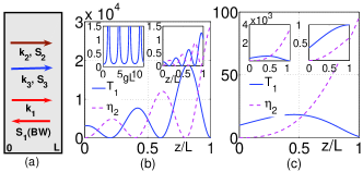
Figure 1(a) depicts the coupling geometry for the proposed TWM BWMOPO. We assume the wave at with the wavevector directed along the -axis to be a NI () signal. Therefore, it is a backward wave because its energy-flow appears directed against the -axis. The medium is illuminated by a higher-frequency PI wave at traveling along the -axis (). The two coupled waves with co-directed wave vectors and generate a difference-frequency idler at , which is also assumed to be a PI wave (). The idler contributes back into the wave at through TWM and thus enables optical parametric amplification (OPA) at by converting the energy of the control field at into the signal. Thus, all of the three coupled waves have their wave vectors co-directed along , whereas the energy flow of the signal wave, , is counter-directed to the energy flows of the two other waves, and . Such a coupling scheme is in strict contrast both with the conventional phase-matching scheme for OPA in ordinary crystals, where all energy-flows and phase velocities are co-directed, and with the TWM BWMOPO outlined above, where the energy flow and wave vector of one of the waves are opposite to all others. The equations for slowly-varying amplitudes of the signal and the idler take the form
| (1) | |||||
| (2) |
Here, are the magnetic components of the fields, ; ; ; is the magnetic nonlinear susceptibility; are absorption indices. The magnitude is assumed constant along the medium. Equation (1) exhibits three fundamental differences as compared with TWM of co-propagating waves in ordinary materials. First, there is an opposite sign of because of . Second, there is an opposite sign before because the energy-flow is directed against the axis . Third, the boundary conditions for are defined at the opposite edge of the sample as compared to and because the energy-flows and are counter-directed. The transmission factor for the negative-index signal, , is derived from the solution to the equations (1) and (2) as OL
| (3) |
Here, , and . The fundamental difference between the spatial distribution of the signal in ordinary and NI materials is explicitly seen at . Then equation (3) reduces to
| (4) |
whereas, in ordinary media, the signal would exponentially grow as . Equations (3) and (4) present a sequence of geometrical resonances as functions of the slab thickness and of the intensity of the control field . Such extraordinary resonances provide for the feasibility of attaining the oscillation threshold for the generation of the entangled counter-propagating left-handed, , and right-handed, , photons without a cavity at . A similar behavior is characteristic for distributed-feedback lasers and is equivalent to a great extension of the NLO coupling length. It is known that even weak amplification per unit length may lead to lasing provided that the corresponding frequency coincides with a high-quality cavity or feedback resonances. The crucial role of the outlined geometrical resonances, as well as the dramatic change caused by amplification of the idler, is illustrated in Fig. 1(b),(c). The main plot in Fig. 1(b) shows the spatial behavior of the signal and the idler at a slightly off-resonant value of , which results in the overall decrease of the transmitted signal. Since the idler grows toward the back facet of the slab at and the signal experiences absorption in the opposite direction, the maximum of the signal for the given parameters appears closer to the back facet of the slab. In general, the distribution of the signal along the slab and, consequently, its output value depends strongly on the difference of the absorption indices for the signal and the idler. As seen from the comparison with the upper right inset, the signal maximum and the slab transparency drop sharply with offset (here, an increase) in the magnitude of from its resonant value. The upper left inset in Fig. 1(b) depicts the resonances in the output signal at . A change in the slab thickness or in the intensity of the control fields leads to significant changes in the distributions of the signal and idler along the slab, which is seen from a comparison of the main plots in Fig. 1(b) and (c). Such a dependence is in stark contrast with its counterpart in PI materials. The role of the additional amplification of the idler provided by the control fields is readily seen from the comparison of the upper left and right insets in Fig. 1(c).
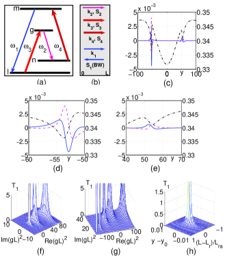
The basic idea of resonant FWM BWMOPO is depicted in Fig. 2(a),(b). A slab of NIM is doped by four-level nonlinear centers [Fig. 2(a)] so that the signal frequency, , falls in the NI domain (), whereas all the other frequencies, , and , are in the PI domain. Here, we look for the possibility to achieve the oscillation threshold for the BW at controlled by two lasers at and . Due to FWM, these three fields generate an idler at , which may experience significant amplification, either Raman or due to the population inversion at the corresponding resonant transition, driven by the control fields. This opens an additional channel that may greatly enhance the coherent energy transfer from the control fields to the signal. The amplified idler contributes back to through FWM and thus causes strongly enhanced parametric amplification of the signal. Unlike ordinary off-resonant NLO, in this scenario many-orders of resonance enhancement in the NLO coupling is accompanied by a strong change of the local optical parameters by the control fields. This is because the control fields may produce a significant population transfer and even inversion, as well as the modulation of the probability amplitudes. Consequently, a split and other modifications of the resonance shapes occur that stem from the quantum interference, which is shown in Fig. 2(c)-(e). Switching between constructive and destructive interference may serve as a tool for harnessing local optical coefficients. Alternatively, such changes can be minimized, so that the major amplification would come directly from the coherent energy transfer from the control fields to the signal and the idler through the FWM coupling. The interference of quantum pathways in the vicinity of the resonances may even lead to the fact that the overall process ceases to be seen as a set of successive one- and multi-photon elementary processes GPRA (and references therein). Similar to the case for TWM, the features of FWM in NIMs employed here appear in stark contrast with those known for the ordinary PI materials due to the fact that all wave vectors are co-directed in order to ensure maximum phase matching but the energy flow appears contra-directed to and, therefore to all other wave vectors [Fig. 2(b)]. Like in the preceding case, this imposes extraordinary features on the nonlinear propagation of the coupled waves. The slowly-varying electric amplitudes of the coupled waves at and are given by the equations
| (5) | |||||
| (6) |
Here, are NLO coupling coefficients; the dielectric permittivity and magnetic permeability, and , are negative at ; ; are the absorption or amplification coefficients; ; ; and are effective electric nonlinear susceptibilities. The amplitudes of the fundamental (control) waves and are assumed constant along the slab. Equations (5) and (6) are similar to equations (1) and (2) and exhibit the same fundamental differences as compared with their counterparts in ordinary PI materials: the sign of the nonlinear polarization term is opposite to that of , which occurs because ; the opposite sign appears for ; and the boundary conditions for must be defined at the opposite side of the sample as compared to those for all other waves. These differences lead to a counterintuitive evolution of the signal and idler along the medium, similar to those discussed for the case of TWM BWMOPO. With the aid of the solutions to equations (5) and (6) OLM , the transmission (amplification) factor for the NI signal, , is given by equation (3), where . A significant difference between the resonant and off-resonant NLO processes investigated here is that the NLO susceptibilities and, therefore, the parameters and become complex and different from each other in the vicinity of the resonances. Hence, the factor may become negative or complex. This indicates an additional phase shift that causes further radical changes in the nonlinear propagation features which can be tailored. Figures 2(c)–(e) show such laser-induced nonlinear interference resonances in the coupling parameter with commensurate real and imaginary parts. Figures 2(f),(g) prove that resonance coupling and, hence, complex or negative magnitudes of may result in the fact that phase matching ceases to be required, and the large phase mismatch introduced by the host material can be compensated through a frequency resonance offset for one of the fields. This is in stark contrast with the optimization of OPA for a weak signal in the off-resonant case for both ordinary materials and NIMs. Note that the requirement of linear phase mismatch is known to optimize OPA for strong fields due to the fact that the ratio of the intensities of the coupled fields and, consequently, the coupling phase varies along the medium. A strikingly similar behavior occurs for the weak signal and homogeneous strong fields in resonant NIMs. To demonstrate the outlined extraordinary NLO features and to prove the proposed possibilities for producing the tailored transparency of NIMs and FWM BWMOPO, we have adopted the following model for numerical simulations presented in Fig. 2(c)–(e). The characteristic for molecules embedded in a solid host were chosen as: energy level relaxation rates , ; partial transition probabilities , , , (all in s-1); homogeneous transition half-widths , , , (all in s-1); , (all in s-1). We assumed that nm and nm. The density-matrix method described in GPRA is used for calculating the intensity-dependent local parameters while accounting for the quantum nonlinear interference effects (NIE). This allows us to account for changes in absorption, amplification, refractive indices and in magnitudes and signs of NLO susceptibilities caused by the control fields. The changes depend on the population redistribution over the coupled levels, which strongly depends on the ratio of the partial transition probabilities. Figure 2(c)-(e) depicts the nonlinear interference structures in the local optical parameters entering into Eq. (3) at the indicated control field strengths and resonance detunings. Here, ; other resonance detunings are defined in a similar way. Coupling Rabi frequencies are introduced as , . The value denotes absorption introduced by the host material, and is the fully resonant value of absorption introduced by the embedded centers at with all driving fields turned off. With the given parameters, the control fields cause essential changes in the level populations, ; ; ; () which is followed by an appreciable population inversion at the idle transition. Laser-induced NIE in the NLO susceptibilities are followed by corresponding changes in absorption and refractive indices. For the above indicated optical transitions, the magnitude s-1 corresponds to control field intensities of 10 - 100 kW/(0.1mm)2. As discussed above, the output signal presents a set of distributed feedback-type resonances that provides for BWMOPO. Optimization of the output signal at is determined by the interplay of absorption, idler gain, FWM and by the wavevector mismatch. This therefore appears to be a multi-parameter problem with sharp resonance dependencies. The results of numerical analysis of Eq.(3) for one such transmission resonance based on the steady-state solutions to the density matrix equations GPRA is given in Fig. 2(h). The intrinsic absorption of the host slab in the NI frequency domain has been assumed equal to 90%. In Fig. 2(h), we also introduce the slab length scaled to the resonance absorption length, . The value of is proportional to the product of the slab length and the number density of the embedded centers. Figure 2(f) displays a narrow geometrical resonance at for the optimum frequency offset for the signal at . This provides the optimum compensation the given phase mismatch, , introduced by the host material. Changes in introduced by molecules are accounted for within the simulations. Fig. 2(h) shows that the width of the oscillation resonance is on the scale of the narrowest (here Raman) transition width and the resonant absorption length. Amplification in the maxima in Fig. 2(h) reaches many orders of magnitude, which indicates the feasibility of cavity-less oscillations. Assuming a resonance absorption cross-section cm2, which is typical for dye molecules, and a concentration of molecules cm-3, we estimate cm-1 and the required slab thickness to be in the microscopic scale . The contribution to the overall refraction index by the impurities is estimated as , which essentially does not change the negative refractive index.
In conclusion, we propose mirrorless generation of a backward wave and entangled counter-propagating left-handed signal and right-handed idler photons in a strongly absorbing microscopic samples of negative-index metamaterials. The proposal implements the backwardness of electromagnetic waves inherent to NIMs and coherent energy transfer from the control fields to the signal through optical parametric coupling. One of the proposed schemes allows for the independent engineering of a negative index and a strong nonlinear-optical response in the metamaterial.
This work was supported by the U. S. Army Research Laboratory and by the U. S. Army Research Office under grants number W911NF-0710261 and 50342-PH-MUR.
References
- (1) V. M. Shalaev, Nat. Photonics 1, 41 (2007).
- (2) S. E. Harris, Appl. Phys. Lett. 9, 114, 1966.
- (3) Yariv, A., Quantum Electronics, 2d ed., New York: Wiley, 1975, Ch. 18.
- (4) C. Canalias and V. Pasiskevicius, Nat. Photonics 1, 459, (2007); J. B. Khurgin, ibid, 446, (2007).
- (5) A. A. Zharov, I. V. Shadrivov, and Y. S. Kivshar, Phys. Rev. Lett. 91, 037401(4) (2003); M. Lapine, M. Gorkunov and K. H. Ringhofer, Phys. Rev. E 67, 065601(R) (2003).
- (6) M. W. Klein, M. Wegener, N. Feth and S. Linden, Opt. Express 15, 5238 (2007).
- (7) A. K. Popov and V. M. Shalaev, Opt. Lett. 31, 2169 (2006); Appl. Phys. B 84, 131 (2006).
- (8) A. K. Popov, S. A. Mysalivets, T. F. George and V. M. Shalaev, Opt. Lett. 32, 3044 (2007).
- (9) A. K. Popov, S. A. Myslivets and T. F. George, Phys. Rev. A 71, 043811(13) (2005).