Dynamic optical lattices: two-dimensional rotating and accordion lattices for ultracold atoms
R. A. Williams, J. D. Pillet, S. Al-Assam, B. Fletcher, M. Shotter andC. J. Foot
Clarendon Laboratory, University of Oxford, Parks Road, Oxford OX1 3PU, United Kingdom
r.williams1@physics.ox.ac.uk
Abstract
We demonstrate a novel experimental arrangement which can rotate a 2D optical lattice at frequencies up to several kilohertz. Ultracold atoms in such a rotating lattice can be used for the direct quantum simulation of strongly correlated systems under large effective magnetic fields, allowing investigation of phenomena such as the fractional quantum Hall effect. Our arrangement also allows the periodicity of a 2D optical lattice to be varied dynamically, producing a 2D accordion lattice.
OCIS codes: (020.0020) Atomic and molecular physics; (020.7010) Trapping
References and links
- [1] M. Lewenstein, A. Sanpera, V. Ahufinger, B. Damski, A. Sen(de), U. Sen, “Ultracold atomic gases in optical lattices: Mimicking condensed matter physics and beyond,” Adv. Phys. 56, 243-379 (2007)
- [2] J. K. Jain, Composite Fermions (OUP, 2007).
- [3] S. Viefers, “Quantum Hall physics in rotating Bose-Einstein condensates,” J. Phys.: Condens. Matter 20 123202.1-123202.14 (2008)
- [4] A. S. Sorenson, E. Demler, M. D. Lukin, “Fractional Quantum Hall States of Atoms in Optical Lattices,” Phys. Rev. Lett. 94, 086803 (2005)
- [5] R.N. Palmer and D. Jaksch, “High field fractional quantum Hall effect in optical lattices,” Phys. Rev. Lett. 96, 180407 (2006)
- [6] R. Bhat, M. Krämer, J. Cooper, M. J. Holland, “Hall effects in Bose-Einstein condensates in a rotating optical lattice,” Phys. Rev. A 76, 043601 (2007)
- [7] D. Jaksch and P. Zoller, “Creation of effective magnetic fields in optical lattices: the Hofstadter butterfly for cold neutral atoms,” New J. Phys. 5, 56.1-56.11 (2003).
- [8] M. Polini, R. Fazio, A. H. MacDonald and M. P. Tosi, “Realization of Fully Frustrated Josephson Junction Arrays with Cold Atoms,” Phys. Rev. Lett. 95, 010401 (2005)
- [9] K. Kasamatsu, “Uniformly frustrated bosonic Josephson junction arrays,” arXiv:0806.2012
- [10] S. Tung, V. Schweikhard, and E. A. Cornell, “Observation of Vortex Pinning in Bose-Einstein Condensates,” Phys. Rev. Lett. 97, 240402 (2006)
- [11] K. Kasamatsu, M. Tsubota, “Dynamical vortex phases in a Bose-Einstein condensate driven by a rotating optical lattice,” Phys. Rev. Lett. 97, 240404 (2006)
- [12] “Optical Lattices and Quantum degenerate 87Rb in reduced dimensions,” John Howard Huckans, PhD thesis, University of Maryland (2006)
- [13] L. Fallani, C. Fort, J. E. Lye, and M. Inguscio, “Bose-Einstein condensate in an optical lattice with tunable spacing: transport and static properties,” Opt. Express 13, 4303-4313 (2005)
- [14] T. C. Li, H. Kelkar, D. Medellin, and M. G. Raizen, “Real-time control of the periodicity of a standing wave: an optical accordion,” Opt. Express 16, 5465-5470 (2008)
- [15] M. Greiner, O. Mandel, T. Essingler, T. W. Hänsch and I. Bloch, “Quantum phase transition from a superfluid to a Mott insulator transition in a gas of ultracold atoms,” Nature 415, 39-44 (2002)
- [16] D. Jaksch, “Optical Lattices, Ultracold Atoms and Quantum Information Processing,” Contemp. Phys. 45, 367-381 (2004).
- [17] B.E.A Saleh and M.C. Teich, Fundamentals of Photonics (Wiley, 1991) pp. 136-139
- [18] M. Born and E. Wolf, Principles of Optics, 7th Edition (CUP, 1999) pp. 178-180
- [19] N. Schlosser, G. Reymond, I. Protsenko and P. Grangier, “Sub-poissonian loading of single atoms in a microscopic dipole trap,” Nature 411, 1024-1027 (2001)
- [20] S. K. Schnelle, E. D. van Ooijen, M. J. Davis, N. R. Heckenberg and H. Rubinsztein-Dunlop, “Versatile two-dimensional potentials for ultracold atoms,” Opt. Express 16, 1405-1412 (2008)
- [21] G. Milne, D. Rhodes, M. MacDonald, and K. Dholakia, “Fractionation of polydisperse colloid with acousto-optically generated potential energy landscapes,” Opt. Lett. 32, 1144-1146 (2007)
1 Introduction
Ultracold atoms in optical lattices present a unique system with which to investigate strongly correlated many-body physics with unprecedented experimental control. Direct quantum simulation of many-body Hamiltonians is of fundamental interest in studying the dynamic behaviour of various condensed matter systems, such as Hubbard and spin models, disordered systems and high temperature superconductivity [1]. Some of the most exotic strongly correlated phenomena in condensed matter physics occur when systems are subjected to large magnetic fields, for example the fractional quantum Hall effect [2]. There is a close analogy between the physics of electron gases under large magnetic fields and rapidly rotating neutral atoms [3]. Recently it has been predicted that strongly correlated 2D systems under large magnetic fields can be simulated using ultracold atoms in a rotating optical lattice, allowing an investigation of high field fractional quantum Hall physics [4, 5, 6]. Other interesting phenomena which can be explored with cold atoms in a rotating lattice include the Hofstadter butterfly [7], fully frustrated Josephson-junction arrays [8, 9], and the dynamics of a vortex array in the presence of a co-rotating lattice [10, 11].
Only one group has previously made a rotating lattice, where a mechanically rotated mask was rotated at [10]. In this paper we present a novel experimental arrangement which allows a 2D lattice to be rotated smoothly at any frequency from 0 to kHz. Ultracold atoms in a lattice of period rotating at kHz experience an effective magnetic flux density of order of one magnetic flux quantum per lattice cell. These high rotation frequencies will allow high field regimes to be explored, where the exotic quantum phenomena discussed above are predicted to occur. The rotation is generated by a dual-axis acousto-optic deflector (AOD) and thus does not suffer from mechanical vibrations and instabilities which would lead to significant heating of atoms in the lattice. The limit of 1kHz in the current apparatus was set by the update rate of the radio frequency synthesis system controlling the AOD, however the optical arrangement can accommodate even higher frequencies.
In addition the arrangement allows for the realization of a 2D accordion lattice, that is, an optical lattice with a dynamically variable periodicity. 1D accordion lattices have previously been demonstrated by a number of groups [12, 13, 14]. Experiments probing the superfluid-Mott insulator transition typically use optical lattices with periodicities where tunnelling between lattice sites is significant [15]. Direct observation of the in-lattice density distribution of a number-squeezed state has not been achieved due to difficulties in achieving an optical system with sufficient resolution. However an accordion lattice could allow for the expansion of the lattice spacing to above the resolution of an optical imaging system () after the Mott insulator had been achieved. Detecting and manipulating atoms at single lattice sites are important criteria for quantum information processing schemes with neutral atoms [16].
2 Experimental arrangement
Optical lattices are formed by standing wave intensity patterns of laser light. While it is common in ultracold atom experiments to use interfering counterpropagating laser beams to produce optical lattices with spacings of another often-used technique is having two beams intersecting at an angle of , producing a lattice with a spacing of . Two parallel beams incident on a lens will form a 1D optical lattice in the focal plane of the lens where they intersect. Such an arrangement was used recently to realize a 1D accordion lattice [14]. The cylindrical symmetry of such an arrangement allowed us to achieve a rotating lattice upon rotation of the parallel beams incident on a lens. Two orthogonal 1D lattices were combined to form a 2D rotating lattice as shown in Fig. 1.
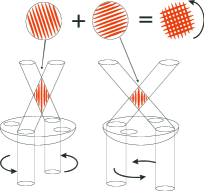
Figure 2 shows the arrangement used to generate two parallel beams of light which rotated out of phase with each other about the optical axis of the system. Clearly an important criterion for a pair of beams is that they must have the same frequency and polarization in order to interfere with one another. The Michelson interferometer-like arrangement shown in Fig. 2 generates two output beams from a single input beam. The long arm of the device contained a lens, L2, which introduced a parallel displacement about the optical axis between the two beams. By generating this second, displaced beam from the first we ensure both beams have the same polarization and frequency and thus will interfere with each other. This would not be the case if two individual AODs were used to rotate two independent beams. The entire setup had cylindrical symmetry about the optical axis of the system and hence rotation could be realized.
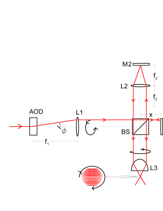
The distances between the non-polarizing beam splitter cube (BS), L2 and M2 in the long arm were chosen such that the output beams from the short and long arms had the same waist and convergence despite the unequal path lengths. This can be seen most easily by realizing that the long arm of the arrangement in Fig. 2 contains a conventional 4f optical imaging system, that is, a one-to-one telescope, mapping the waist and wavefront curvature of the incoming beam onto the beam leaving the long arm [17]. The beam incident on the BS did not therefore need to be collimated to ensure that the two output beams had identical Gaussian characteristics. The unequal path lengths of the different arms mean that the laser must have a coherence length greater than the path difference, however this requirement is easily satisfied by lasers typically used for creating optical lattices and by a reasonable choice for L2. For L2 we used a 10cm focal length achromatic doublet, while a Titanium-doped Sapphire laser operating at 830nm (coherence length ) was used for the lattice beams.
We relate the electric field distributions in the front and back focal of L3 using the geometrical optics argument shown in Fig. 3, considering both the ideal case of a thin lens and the more realistic case of a high numerical aperture objective lens. Neglecting the Gaussian envelope of the beams the electric field in the back focal plane of L3 is
| (1) | |||||
| (2) |
where designates coordinates in the back focal plane of L3, is the focal length of lens L3, and are the wavevectors of the intersecting beams as shown in Fig. 3 and is the angular frequency of the laser beams. The resultant intensity thus has the form
| (3) |
Equation 2 considers two beams with identical linear polarization parallel to the resultant intensity fringes. While it is always possible to arrange the beam polarizations like this for a two-dimensional accordion lattice this is not the case for a rotating lattice. If using linear polarization with a rotating beam the electric field component in the plane of the lattice will change with rotation, leading to a modulation in lattice depth. This problem can be eliminated by using the same circular polarization for a pair of interfering beams. Given the symmetry of the arrangement the electric field component in the plane of the interference fringes remains constant as the lattice rotates, and there is no modulation of the lattice depth.
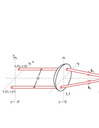
From the geometry shown in Fig. 3 (assuming a thin lens) wavevectors , can be expressed as , where are the coordinates of the beams in the front focal plane of L3. However high numerical aperture objective lenses have a finite thickness and are designed to obey the Sine Condition [18] to ensure good imaging of off-axis objects. A consequence of obeying the Sine Condition is that the wavevectors , make a different angle to the optical axis, with . The optical system of Fig. 2 created two beams in the front focal plane of L3 such that , . Equation 3 then becomes
| (4) |
We controlled and by steering the beam with the AOD, e.g. for a lattice rotating at an angular frequency of , , , where is the separation of the two beams in the front focal plane of L3. Substituting this into Equation 4 one finds
| (5) |
where is the periodicity of the lattice. Li et al [14] measured the periodicity of lattices formed in the focal plane of an achromatic doublet and found this expression for the lattice spacing to be accurate for intersection angles up to . Equation 5 describes a one-dimensional lattice rotating with angular frequency .
An accordion lattice can also be implemented in this arrangement by using the AOD to change , the separation of the beams in the front focal plane of L3. is determined by the angle of deflection of the beam from the optical axis ( in Fig. 2) and the focal length of L1, . The smallest lattice spacing achievable, , is set by the maximum intersection angle of the beams and hence the numerical aperture (N.A.) of objective lens L3, . The minimum lattice periodicity possible is of considerable importance in experiments with cold atoms as quantum tunnelling and the mutual interaction energy of two atoms on the same site become negligible at larger lattice spacings. High N.A. objective lenses have been successfully interfaced with cold atoms, for example in [19] an N.A. of 0.7 was used. For 830nm light this would give nm. The largest possible lattice period was limited by the Gaussian profile of the laser beams, that is, to achieve a reasonable number of fringes in the central, uniform intensity region of the beam profile is required to be smaller than the beam waist.
The generation of rotation of the initial single beam was produced using a dual axis AOD (an Isomet LS110A-830XY). The center frequency of the AOD was 50MHz, with a bandwidth of 25MHz. The radio frequency (rf) signal to the AOD controlling the deflection was generated using a custom-made Direct Digital Synthesis (DDS) based system, providing powerful and fast control of the beam deflection. AODs are specifically optimised for deflecting laser beams, giving large deflection angles and a reasonably uniform diffraction efficiency over their bandwidth. However some power variation in the deflected beam remained, which could be as much as in our arrangement. Such power fluctuations are undesirable when implementing an optical lattice, and we were able to compensate for the deterministic change in diffraction efficiency with deflection angle by calibrating the rf wave amplitude appropriately at each frequency. Alternatively a feed forward mechanism could be used to correct for the power variation as was done in [20], or for low rotation frequencies the beam power after the AOD could be actively stabilized using a feedback arrangement.
While Fig. 2 shows the arrangement for generating a single set of rotating fringes it is straightforward to combine two orthogonal sets of fringes to create a two-dimensional optical lattice. The most straightforward and effective way to do this is to introduce a second AOD to rotate a beam out of phase with the first. These two rotating beams can then be combined at a beam splitter cube before both entering the Michelson interferometer-like optics. In order to prevent interference between the two one-dimensional lattices one pair of lattice beams must be detuned by MHz relative to the other pair. This can be achieved by operating the two AODs about different center frequencies which are separated by MHz. In this case the rf signal applied to each AOD is modulated sinusoidally, with the center frequency for each AOD separated by a frequency larger than twice the modulation amplitude. Alternatively an acoustic-optic modulator can be used to shift the frequency of a beam before it enters an AOD.
3 Demonstration of two-dimensional rotating and accordion lattices
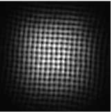
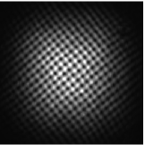
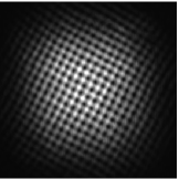
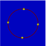
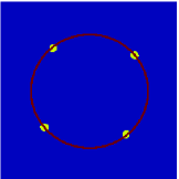
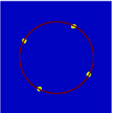
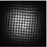
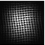
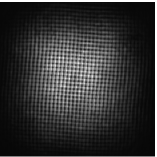
Figures 4-4 show snapshots of the optical lattice, taken while the optical lattice was rotating, indicating the lattice quality was not adversely affected by rotation (see also video online, showing the lattice rotating at 1Hz). Figures 4-4 are the 2D Fourier transforms of 4-4 respectively. The red circle passing through the peaks is the same in each image, and highlights that the periodicity of the lattice did not change as the lattice was rotated.
Figure 5 (multimedia online) displays the two-dimensional accordion lattice. As with rotation the lattice visibility can be seen to remain excellent as the periodicity of the lattice changes.
The images of Figs. 4 and 5 were taken by a CCD camera at the focus of objective lens L3. The full scale of each image is mm. In order to achieve reasonable lattice periodicities that the camera could resolve for demonstrating the dynamic nature of the lattice we used a low N.A., 25cm focal length lens for L3. For a cold atom experiment a high N.A. lens would be used, for example, we have since used an objective lens with an N.A. of 0.27 to load cold atoms into lattices with periodicities ranging from 1.8m to 18m, details of which will be published in future work.
The advantages that the AOD-generated movement of the lattice beams brings to rotation, that is, fast and smooth rotation at a precise frequency, also apply to the two-dimensional accordion lattice. The lattice spacing can be changed very quickly and precisely, with a maximum speed which is limited in our arrangement by the update rate of the digital synthesis system generating the rf signal for the AODs. For example we could change the lattice spacing by a factor of 10 in under 100ms.
4 Conclusion
We have presented a versatile optical arrangement which can generate two-dimensional rotating and accordion lattices. The scheme is based around an acousto-optic deflector, giving excellent, stable control over both rotation frequency and lattice periodicity as well as allowing a large range of rotation frequencies to be achieved. Such a rotating lattice has important application in direct quantum simulation using ultracold atomic systems. The scheme presented here for dynamically controlling light intensity patterns could be applied to biophysics where intensity patterns generated by AODs have been used to optically sort particles flowing in water [21].
Acknowledgements
This work is supported by EPSRC, QIP IRC and ESF.