Elastic and Chemical Contributions to the Stability of Magnetic Surface Alloys on Ru(0001)
Abstract
We have used density functional theory to study the structural stability of surface alloys. Our systems consist of a single pseudomorphic layer of on the Ru(0001) surface, where = Fe or Co, and = Pt, Au, Ag, Cd, or Pb. Several of the combinations studied by us display a preference for atomically mixed configurations over phase-segregated forms. We have also performed further ab initio calculations to obtain the parameters describing the elastic interactions between atoms in the alloy layer, including the effective atomic sizes at the surface. We find that while elastic interactions favor alloying for all the systems considered by us, in some cases chemical interactions disfavor atomic mixing. We show that a simple criterion (analogous to the Hume-Rothery first law for bulk alloys) need not necessarily work for strain-stabilized surface alloys, because of the presence of additional elastic contributions to the alloy heat of formation, that will tend to oppose phase segregation.
pacs:
68.35.-p, 68.35.Dv, 68.55.-aI Introduction
It has been known since ancient times that alloying two metals can give rise to a new material with properties that are improved over those of the constituent metals. For example, alloys can have superior mechanical or magnetic properties, an increased resistance to corrosion, or constitute good catalysts. However, not all pairs of metals form stable alloy phases. The rules governing alloy formation in the bulk were first formulated by Hume-Rothery.Hume-Rothery The first of these empirical laws states that if the atomic size mismatch is greater than 15%, phase segregation is favored over the formation of solid solutions. Thus, many pairs of metals are immiscible (or nearly so) in the bulk.
In recent years, it has become apparent that surface science can extend the chemical phase space available for the search for new alloy systems. It has long been known that bulk alloys exhibit surface segregation, so that the chemical composition at the surface can differ considerably from that in the bulk. However, the field of surface alloying gained additional interest when it was discovered that even metals that are immiscible in the bulk can form stable surface alloys as a result of the altered atomic environment at the surface.Nielsen ; Roder ; Neugebauer These alloys display atomic mixing that is confined to the surface layer or, in some cases, the top few layers. These results were explained by Tersoff,Tersoff who argued that in cases where there is a large size mismatch, as a result of which the energetics are dominated by strain effects, alloying will be disfavored in the bulk but favored at the surface.
Subsequently, another class of surface alloys has emerged, where two metals that differ in size are co-deposited on a third metal of intermediate size. In such systems, any single-component pseudomorphic layer will be under tensile or compressive stress (that may or may not be relieved by the formation of dislocations);AgonRu however if the two elements were to mix, the stress would presumably be considerably relieved. Thus, the strain imposed by the presence of the substrate promotes alloying in the surface layer. Some examples of such strain-stabilized surface alloys are an Ag-Cu monolayer on Ru(0001),AgCuonRu ; Schick ; Schick1 Pd-Au/Ru(0001), PdAuonRu and Pb-Sn/Rh(111).PbSnonRh
Hitherto, the guiding principle in the search for such systems has been the rule-of-thumb that the (bulk) nearest-neighbor (NN) distance of the substrate should be the average of the NN distances of the two overlayer elements. However, this simple criterion does not necessarily work. For example, Thayer et al. have studied the Co-Ag/Ru(0001) system.Thayer ; Thayer1 At first sight, this system would seem to be a good candidate for the formation of a strain-stabilized surface alloy, since the NN distance for Ag is larger than that of Ru by 8%, while that of Co is smaller by 7%. However, instead of forming an atomically mixed structure, it was found that the stable structure consisted of Ag droplets surrounded by Co. After doing a combined experimental and theoretical study, these authors concluded that chemical bonding between Ag and Co is disfavored in this system, and the observed structure results from a lowering of stress at the boundary between Co and Ag islands.
In this paper, we examine ten different bi-metallic systems on a Ru(0001) substrate. Some of the questions that we hope to address include: (i) is it only the mean size of the overlayer atoms that matters, or do individual sizes also matter? (ii) can one develop a criterion based on atomic size that will predict whether or not a surface alloy will form? (iii) how different are atomic sizes at the surface compared to those in the bulk?, and (iv) what is the relative importance of elastic and chemical interactions?
The bi-metallic systems we have considered all consist of one magnetic metal (Fe or Co) and one non-magnetic metal (Pt, Ag, Au, Cd or Pb), co-deposited on Ru(0001) to form a surface alloy of the form , where denotes the Ru substrate. Such systems, involving one magnetic and one non-magnetic element, are of interest because alloying can, in some cases, improve magnetic properties. Conversely, in some applications,Tober ; Yang one would prefer that instead of mixing at the atomic level, the system should spontaneously organize into a pattern consisting of alternating domains of the magnetic and the non-magnetic element. Ru(0001) was chosen as the substrate, in part because of its intermediate NN distance, and in part because its hardness and immiscibility with the other elements make it less likely that the alloy elements will penetrate into the bulk. The bulk NN distances, , of the two magnetic metals Fe and Co, are about 7-8% less than , the NN separation in the Ru substrate, while all five non-magnetic metals we have considered have bulk NN distances, , larger than that of Ru. However, the metals we have chosen display a large variation in size: the NN distance in Pt is approximately 3% more than that in Ru, while in Pb the discrepancy is 26%. Accordingly, only Fe-Pt and Co-Pt fall within the 15% range of the Hume-Rothery criterion for bulk alloys; alloys of Fe and Co with Au and Ag fall slightly outside this range, while those with Cd and Pb fall well outside the range. If there is a size-dependent trend that determines whether or not alloying is favored, then one might hope that it will show up upon examining these ten systems. In Table I, we have given the average NN separation, , using experimental values for the bulk metals. Upon examining how close these values lie to = 2.70 Å, one might expect (using the simple criterion mentioned above) that Fe-Au, Fe-Ag, Co-Au and Co-Ag might be good candidates for forming strain-stabilized surface alloys, and Fe-Cd, Co-Cd, Fe-Pt and Co-Pt may be possibilities, but Fe-Pb and Co-Pb surface alloys should be highly unlikely to form. As we will show below, these simple-minded expectations are not necessarily borne out.
Of the ten systems we consider in this paper, we are aware of previous studies on only two of them: Co-Ag/Ru(0001),Thayer ; Thayer1 and Fe-Ag/Ru(0001).Yang In both these cases, it was found that chemical interactions dominate over elastic ones, and the atomically mixed phase is disfavored.
| Pt | Au | Ag | Cd | Pb | |
|---|---|---|---|---|---|
| Fe | 2.63 | 2.69 | 2.69 | 2.73 | 2.99 |
| Co | 2.64 | 2.70 | 2.70 | 2.75 | 3.01 |
II Computational details
All the calculations are done using ab initio spin polarized density functional theory with the PWscf package of the Quantum-ESPRESSO distribution. pwscf A plane-wave basis set is used with a kinetic energy cutoff of 20 Ry. The charge-density cutoff value is taken to be 160 Ry. Ultrasoft pseudopotentials uspp are used to describe the interaction between ions and valence electrons. For the exchange correlation functional, a Generalized Gradient Approximation (GGA) of the Perdew-Burke-Ernzerhof form pbe is used. As all the systems are metallic, the Methfessel-Paxton smearing technique mp is used with the smearing width equal to 0.05 Ry.
Convergence with respect to the basis size and the k-point grid has been carefully verified. For the bulk structure calculations, we have used the common crystal phase of each element. The k-points used for Brillouin zone integrations form an 888 Monkhorst-Pack gridgrid for bulk calculations, and a 441 grid for surface calculations. To study the surface properties, the supercell approach is used, with a unit cell that includes a slab and some vacuum layers. The slab used corresponds to a surface unit cell, and contains six Ru layers to model the substrate. Our results for the energetics were obtained with one alloy overlayer (deposited on one side of the substrate) and seven vacuum layers (approximately 17.4 Å); we have allowed the alloy overlayer and the three topmost layers of Ru to relax, using Hellmann-Feynman forces. However, when performing calculations to see how the surface stress of monolayers of or on varied with in-plane distance, the monolayer was deposited symmetrically on both sides of the slab, and the central layers of the slab were held fixed, while the outer layers on both sides were allowed to relax.
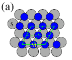
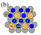
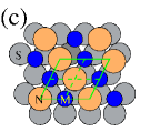
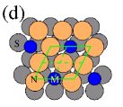
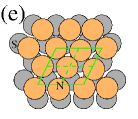
The (0001) surface of Ru is a closed-packed surface, on which typically one of the hollow sites, either hexagonal-closed packed (hcp) or face-centered cubic (fcc), is energetically preferred. We have allowed for both possibilities. The use of a (22) unit cell enables us to study five different compositions as shown in Fig. 1. Because of the small size of the unit cell, there is only one distinct configuration corresponding to each composition.
In this particular study, we have considered only a single, pseudomorphic and ordered layer of an alloy on the substrate slab. The general observation that reconstruction in the overlayer occurs only after a certain critical thickness of deposited material, validates our assumption that the monolayer (of either a single metal or an alloy) remains pseudomorphic. For most systems studied previously consisting of a single metal on Ru(0001), it is found that the first overlayer of the metal does not reconstruct. However, Ag on Ru(0001) is an exception, in which a misfit dislocation structure has been observed, even for submonolayer films.AgonRu
III Results and discussion
The substrate element, Ru, has the hcp structure in the bulk. Upon optimizing the geometry for bulk Ru, using the experimental ratio of 1.584, we obtain (which is also the NN distance ) as 2.74 Å, which is close to the experimental value of 2.70 Å.AscMer For bulk Fe, Co, Pt, Au, Ag, Cd and Pb we obtain NN distances of 2.47, 2.49, 2.83, 2.93, 2.95, 3.04 and 3.56 respectively. Again, all these numbers match very well with the corresponding experimental values.
For a single-component monolayer on Ru(0001), we find that both the magnetic elements prefer to occupy the hcp sites; occupying instead the fcc sites costs about 75 meV per surface atom. However, for all the non-magnetic elements, with the exception of Pt, we find that the fcc site is very slightly favored over the hcp one, with an energy difference of the order of 4 meV per surface atom. In the rest of this paper, we work with the structures corresponding to the favored site occupancies for each system.
| Elt. | Fe | Co | Pt | Au | Ag | Cd | Pb |
|---|---|---|---|---|---|---|---|
| (Å) | 2.08 | 2.01 | 2.79 | 2.95 | 2.92 | 2.97 | 3.00 |
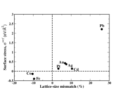
Upon depositing the single-component monolayers of either or on Ru(0001), and relaxing the geometry, we find that , the interplanar distance between the overlayer and the topmost Ru layer, varies significantly depending upon the element constituting the overlayer. Our results for are given in Table 2; they may be compared with 2.17 Å, which is the value of , the interplanar distance in bulk Ru. We see that for the magnetic elements, , whereas for the non-magnetic elements, . We also see a similar pattern upon examining our results for the surface stress of these systems (see Fig. 2): the /Ru systems are under tensile stress, whereas all the /Ru systems are under compressive stress. All these findings are consistent with the idea that the atoms at the Ru surface would like to increase their ambient electron density, whereas the opposite is true for the atoms; this is what one would expect from simple size considerations using the values of for all the metals.
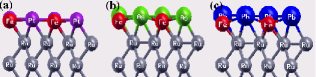
For the surface alloys, we find that in every case considered by us, the hcp site is favored over the fcc site. The difference in energy between the two sites varies from 10 to 70 meV per surface atom. Upon relaxing the alloy structures, we find that the surface layer can exhibit significant buckling; this follows the trends expected from the atomic-size mismatch between the constituent elements. Thus, Pt alloys do not show any visible buckling, while Pb alloys show the maximum amount of buckling among all the ’s studied (see Fig. 3).
The stability of an alloy phase relative to the phase-segregated phase can be determined by calculating the formation energy, which is defined as follows:
| (1) |
where is the ground state energy per surface atom for a single layer of on the substrate . When is negative, the two metals prefer to mix rather than to segregate, and hence the alloy phase is more stable.
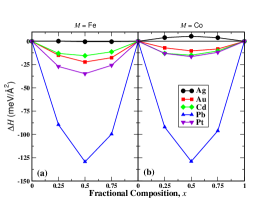
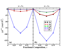
Our results for as a function of a composition are presented in Fig. 4. Note that in all cases, we find that is roughly symmetric about , suggesting that pairwise interactions are dominant. For both Fe and Co , alloys with Ag are found to be the least stable and alloys with Pb appear to be the most stable. However, though Fe and Co have almost the same , the values of , and even the order of stability, are not identical in the two cases. Similarly, despite having very close values of , Au and Ag display very different behavior: alloys of the former are stable, whereas Fe-Ag alloys are right at the boundary of stability, and Co-Ag alloys are unstable. These observations support the view that chemical effects may, in some cases, be quite important – and even dominate over elastic interactions. Our finding that atomic-level mixing is disfavored for Fe-Ag and Co-Ag is in keeping with the observations of previous authors.Thayer ; Thayer1 ; Yang We point out that our results underline the fact that need not necessarily be a good criterion for atomic-level mixing to be favored (see Table 1).
It is generally accepted that there are two main contributions to the stability of such surface alloys: an elastic contribution, and a chemical contribution.Thayer1 ; Ozolins We would like to separate out the two, if possible. In order to do so, we assume that the elastic interactions are given by a sum of NN contributions, with each pairwise term taking the form of a Morse potential:
| (2) |
where is the distance between the NN atoms and , is the equilibrium bond length, and and are parameters related to the depth and width, respectively, of the potential well.
For each composition, the elastic energy is written as the sum of individual bond energies of the Morse form, by counting the total number of -, - and - bonds in each (2 2) unit cell. Accordingly, for = 0.25, 0.5 and 0.75, we obtain the elastic contribution to the formation energy as:
| (3) | ||||
| (4) | ||||
| (5) |
Note that Equations (3) and (5) are identical, i.e., within our model, the elastic interactions lead to a that is symmetric about . It is also important to note that for bulk alloys of and , there are no terms analogous to the second and third terms on the right-hand-sides of the above equations. Due to the presence of the substrate, these terms have to be evaluated not at or (where they would lead to a zero contribution) but at the substrate spacing . As a result of this, one can expect mixing rules to be quite different for surface alloys than for bulk alloys; we will return to this point further below.
In order to evaluate Eqs. (3)–(5), we need values for the Morse parameters , and , which appear in Eq. 2. We obtain these by computing the surface stress, , for each single-component monolayer as a function of the in-plane bondlength . In principle, this could be obtained by compressing or expanding a monolayer of or on . However, this would make the overlayer incommensurate with the substrate, leading to a surface unit cell which is too large for practical computation. Hence, we instead compress or expand the whole slab to perform calculations at different , and then subtract out the contribution from the substrate layers to the total stress, so as to get the surface stress at each .Pushpa In order to carry out this procedure, we make use of the following equation:
| (6) |
Here, is the surface stress at an intraplanar bond length , for a slab with atomic layers and dimension (which includes the vacuum) along , and is the component of the “volume stress” for the slab (i.e., it has dimensions of force per unit area, as opposed to the surface stress, which has units of force per unit length). Similarly, is the -component of the volume stress for a bulk Ru cell that has been stretched or compressed to the same as the slab. Note that the geometrical factors in the last two terms are specific for the hcp structure.
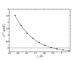
The Morse parameters for an - bond can be extracted from the plot of versus for each single-component overlayer of or on the Ru surface. As an example, our results for the variation of surface stress with in-plane strain, for a monolayer of Au on Ru(0001), are shown in Fig. 5; qualitatively similar curves are obtained for other elements. The value of or is given by the value of at which the graph crosses the -axis, while the values of and are obtained by fitting the curve to an expression derived from a Morse potential. The values thus obtained for all seven overlayer elements are given in Table 3. The value of serves as a measure of the effective size of an atom when placed on the Ru(0001) surface. The values obtained by us from calculations of surface stress are roughly consistent with estimates obtained from a consideration of the buckling of the surface alloys, together with a hard-sphere model. Note that for both the magnetic elements , is smaller than , whereas for all the non-magnetic elements considered by us, is greater than . However, the values of are found to be different from , in some cases quite significantly so. This difference is due to the presence of both the surface (i.e, no neighbors above) and the substrate (different neighbors below). It is interesting to note that for Fe/Ru(0001), , whereas for all the other elements, This is presumably because Fe in the bulk form has the body centered cubic (bcc) structure with a coordination number of 8, whereas all the other elements have either the fcc or hcp structure with 12-fold coordination. As a result, only for Fe are the overlayer atoms more effectively coordinated when placed on a Ru surface. However, apart from such general observations, we were unable to discern any simple relationship connecting the values of and .
| / | (eV) | (Å-1) | (Å) | (Å) |
| Fe | 0.1309 | 2.412 | 2.56 | 2.47 |
| Co | 0.5827 | 2.052 | 2.37 | 2.49 |
| Pt | 0.6744 | 1.817 | 2.79 | 2.83 |
| Au | 0.4341 | 1.797 | 2.90 | 2.93 |
| Ag | 0.3638 | 1.669 | 2.92 | 2.95 |
| Cd | 0.6564 | 1.680 | 2.79 | 3.04 |
| Pb | 0.2027 | 1.563 | 3.42 | 3.56 |
It remains to obtain the Morse parameters for - bonds. In analogy with the Lorentz-Berthelot mixing rules, the - bond parameters are assumed to have the form, ; and . In Table 4 we have tabulated the values of . These should compared to the bulk Ru NN spacing (= 2.74 Å). It is also instructive to compare the values in Table 4 with those in Table 1; one finds that there is no dramatic change upon accounting for altered surface sizes.
| (Å) | Pt | Au | Ag | Cd | Pb |
|---|---|---|---|---|---|
| Fe | 2.67 | 2.73 | 2.74 | 2.67 | 2.99 |
| Co | 2.58 | 2.63 | 2.64 | 2.58 | 2.89 |
Our results for the elastic contribution to the formation energy, evaluated using Equations (3) to (5), are displayed in Fig. 6. We find that for all ten combinations considered by us, elastic interactions always favor mixing of the two overlayer elements, in accordance with the predictions by Tersoff.Tersoff
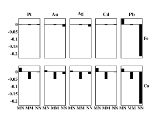
At first sight, our most surprising result appears to be our finding that for both magnetic elements, the Pb alloys are the most stable, though upon examining Table 1 or Table 4, one might think that this is unlikely. However, this is because for surface alloys, unlike bulk alloys, the phase-segregated forms can cost a high elastic energy, because of the presence of the substrate. Since pseudomorphic Pb/Ru(0001) costs a great deal in elastic energy, the mixed form is correspondingly favored. In order to make this argument clearer, in Fig. 7, we have separated out the individual contributions to the right-hand-side of Equation 4. The first (-) term is always positive, while the second (-) and third (-) terms are always negative. In order for to be negative, the first term should be small (the simple mixing rule applies only to this term), while the second and third terms should be large in magnitude. The first term is found to follow the expectations from an elementary consideration of sizes (either at the bulk or at the surface): Ag and Au alloys are the most favored, followed by Pt and Cd, and then Pb. It is interesting to note that both Cd and Pt alloys have roughly the same contribution from this first term; this is because Cd undergoes a relatively large contraction in size at the surface, relative to the bulk. A Co monolayer on Ru(0001) is relatively unhappy (i.e., the contribution to the elastic part of the formation energy is significant and negative), and a Pb monolayer on Ru(0001) is extremely unfavorable energetically. As a result of these two facts, elastic interactions favor the formation of Co- alloys over Fe- alloys, and lead to the high stability against phase segregation of -Pb alloys. However, one should be cautious in interpreting these results, since we have made the assumption that the alloys as well as phase-segregated monolayers remain pseudomorphic. For the alloys, this is probably a valid assumption, since the elastic energy (corresponding to the first bars in Fig. 7) is small, i.e., the stress is unlikely to be high enough to drive the overlayer to relax. Despite the significant elastic energy contained in a Co/Ru(0001) monolayer, it does not reconstruct.Hwang2 However, for Pb/Ru(0001), the very high elastic energy makes it seem possible that this system might reconstruct, presumably via a network of misfit dislocations; we are not aware of any experimental information on this system. Thus, the high stability we obtain for -Pb alloys may be misleading; the stability would be lowered if the phase segregated form were to reconstruct (since the third term in the elastic energy would then be decreased in magnitude).
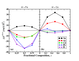
Finally, in Fig 8, we display our results for the chemical contribution to the formation energy, obtained by subtracting out the data in Fig. 6 from that in Fig. 4. When only chemical interactions are considered, Fe alloys are more favorable than Co alloys. From this plot, we note that the stability of Pt alloys is largely due to the favored chemical bonds between Fe-Pt and Co-Pt ; this is consistent with the fact that these intermetallic systems also form bulk alloys. The Ag alloys are not stable because Co-Ag and Fe-Ag bonds cost very high chemical energy, which cannot be offset by elastic energy; this too is consistent with previous results.Thayer ; Thayer1 ; Yang Also note that Fe-Au bonds favor mixing, whereas Co-Au bonds cost energy, which explains the particular order of stability observed in the ab initio results.
IV Summary and Conclusions
In this paper, we have attempted to gain an understanding into the factors governing the energetics of strain-stabilized surface alloys, by performing ab initio calculations on ten combinations involving a magnetic and a non-magnetic metal co-deposited on a Ru(0001) substrate. In many cases, we find the surface alloy to be stable, even though the constituent elements are immiscible in the bulk.
We find that the stability (against phase-segregation) does not correlate with expectations based upon the simple argument that the mean atomic size should be as close as possible to the substrate lattice spacing. One reason for this is that though elastic interactions are an important mechanism governing stability, chemical interactions can also play a crucial role. In some cases, the latter are large enough to disfavor atomic-level mixing, even if it helps in lowering the elastic energy. A second complicating factor is that unlike for bulk alloys, for such strain-stabilized surface alloys, the phase segregated forms can also cost elastic energy. Thus, there are three factors that determine whether or not mixing takes place at the atomic level: (i) the elastic energy of the alloy phase, (ii) the elastic energies of the phase-segregated monolayers on the substrate, and (iii) chemical interactions. Because of this complicated situation, a simple criterion, analogous to the first Hume-Rothery rule for bulk alloys, does not seem possible for such systems.
We have also found that effective atomic sizes on the Ru substrate are not equal to the bulk size; in some cases this difference is small, while in other cases it is large. Several alloys involving a magnetic and a non-magnetic element on a Ru(0001) surface are found to be stable against phase segregation; this is primarily because the effective size of the magnetic elements is smaller than the nearest-neighbor distance in the substrate, while that of the non-magnetic elements is larger, even after accounting for altered sizes at the surface. Of the systems we have considered, we feel that Fe-Au, Fe-Cd and Co-Cd are particularly promising candidates that would be worth experimental investigation. In these systems, both chemical and elastic interactions promote alloying. We have also found that surface alloys involving Pb and either Fe or Co appear to be very resistant to phase segregation; however, this conclusion is dependent on our assumption that a monolayer of Pb on Ru(0001) does not reconstruct, which may or may not be valid.
Acknowledgements.
We acknowledge helpful discussions with Sylvie Rousset, Vincent Repain and Yann Girard. Funding was provided by the Indo-French Centre for the Promotion of Advanced Research. Computational facilities were provided by the Centre for Computational Material Science at JNCASR.References
- (1) W. Hume-Rothery and H. M. Powell, Z. Krist. 91, 13 (1935).
- (2) L. P. Nielsen, F. Besenbacher, I. Stensgaard, E. Lægsgaard, C. Engdahl, P. Stoltze, K. W. Jacobsen and J. K. Nørskov, Phys. Rev. Lett. 71, 754 (1993).
- (3) H. Röder, R. Schuster, H. Brune and K. Kern, Phys. Rev. Lett. 71, 2086 (1993).
- (4) J. Neugebauer and M. Scheffler, Phys. Rev. Lett. 71, 577 (1993).
- (5) J. Tersoff, Phys. Rev. Lett. 74, 434 (1995).
- (6) R. Q. Hwang, J. C. Hamilton, J. L. Stevens and S. M. Foiles, Phys. Rev. Lett. 75, 4242 (1995).
- (7) J. L. Stevens and R. Q. Hwang, Phys. Rev. Lett. 74, 2078 (1995).
- (8) M. Schick, J. Schäffer, K. Kalki, G. Ceballos, P. Reinhardt, H. Hoffschulz and K. Wandelt, Surf. Sci. 287/288, 960 (1993).
- (9) M. Schick, G. Ceballos, Th. Peizer, J. Schäffer, G. Rangelov, J. Stober and K. Wandelt, J. Vac. Sci. Technol. A 12, 1795 (1994).
- (10) B. Sadigh, M.Asta, V. Ozoliņš, A. K. Schmid, N. C. Bartelt, A. A. Quong and R. Q. Hwang, Phys. Rev. Lett 83, 1379 (1999).
- (11) J. Yuhara, M. Schmid and P. Varga, Phys. Rev. B 67, 195407 (2003).
- (12) G. E. Thayer, V. Ozolins, A. K. Schmid, N. C. Bartelt, M. Asta, J. J. Hoyt, S. Chiang and R. Q. Hwang, Phys. Rev. Lett. 86, 660 (2001).
- (13) G. E. Thayer, N. C. Bartelt, V. Ozolins, A. K. Schmid, S. Chiang and R. Q. Hwang, Phys. Rev. Lett. 89, 036101 (2002).
- (14) E.D. Tober, R.F.C. Farrow, R.F. Marks, G. Witte, K. Kalki, and D.D. Chambliss, Phys. Rev. Lett. 81, 1897 (1998).
- (15) B. Yang, T. Muppidi, V. Ozolins and M. Asta, Phys. Rev. B 77, 205408 (2008).
- (16) S. Baroni, S. de Gironcoli, A. Dal Corso and Paolo Giannozzi, http://www.pwscf.org/
- (17) D. Vanderbilt, Phys. Rev. B 41,7892 (1990).
- (18) J. P. Perdew, K. Burke and M. Ernzerhof, Phys. Rev. Lett. 77,3865 (1996).
- (19) M. Methfessel and A. T. Paxton, Phys. Rev. B 40, 3616 (1989).
- (20) H. J. Monkhorst and J. D. Pack, Phys. Rev. B 13, 5188 (1976).
- (21) N. W. Ashcroft and N. D. Mermin, Solid State Physics (Thomson Asia Pte. Ltd, Bangalore, 2004).
- (22) V. Ozoliņš, M. Asta and J. J. Hoyt, Phys. Rev. Lett. 88, 096101 (2002).
- (23) R. Pushpa and S. Narasimhan, Phys. Rev. B 67, 205418 (2003).
- (24) R. Q. Hwang, C. Günther, J. Schröder, S. Günther, E. Kopatzki and R. J. Behm, J. Vac. Sci. Technol. A 10, 1970 (1992).