Spin-transfer torque induced reversal in magnetic domains
Abstract
Using the complex stereographic variable representation for the macrospin, from a study of the nonlinear dynamics underlying the generalized Landau-Lifshitz(LL) equation with Gilbert damping, we show that the spin-transfer torque is effectively equivalent to an applied magnetic field. We study the macrospin switching on a Stoner particle due to spin-transfer torque on application of a spin polarized current. We find that the switching due to spin-transfer torque is a more effective alternative to switching by an applied external field in the presence of damping. We demonstrate numerically that a spin-polarized current in the form of a short pulse can be effectively employed to achieve the desired macro-spin switching.
keywords:
Nonlinear spin dynamics, Landau-Lifshitz equation, Spin-transfer torque, Magnetization reversalPACS:
75.10.Hk, 67.57.Lm, 75.60.Jk, 72.25.Ba1 Introduction
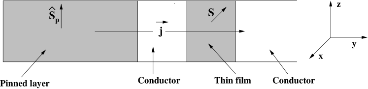
In recent times the phenomenon of spin-transfer torque has gained much attention in nanoscale ferromagnets[1, 2, 3]. Electromigration refers to the recoil linear momentum imparted on the atoms of a metal or semiconductor as a large current is conducted across. Analogously, if the current is spin-polarized, the transfer of a strong current across results in a transfer of spin angular momentum to the atoms. This has lead to the possibility of current induced switching of magnetization in nanoscale ferromagnets. With the success of GMR, this has immense application potential in magnetic recording devices such as MRAMs[3, 4, 5, 6]. The phenomenon has been studied in several nanomagnetic pile geometries. The typical set up consists of a nanowire[3, 7, 8, 9, 10, 11], or a spin-valve pillar, consisting of two ferromagnetic layers, one a long ferromagnetic pinned layer, and another small ferromagnetic layer or film, separated by a spacer conductor layer (see Figure 1). The pinned layer acts as a reservoir for spin polarized current which on passing through the conductor and on to the thin ferromagnetic layer induces an effective torque on the spin magnetization in the thin film ferromagnet. A number of experiments have been conducted on this geometry and the phenomenon has been convincingly confirmed [12, 13, 14, 15]. Although the microscopic quantum theory of the phenomenon is fairly well understood, interestingly the behavior of the average spin magnetization vector can be described at the semi-classical level by the LL equation with an additional term[16].
From a different point of view, several studies have focused on magnetic pulse induced switching of the macro-magnetization vector in a thin nanodot under different circumstances [17, 18, 19, 20]. Several experimental studies have also focussed on spin-current induced switching in the presence of a magnetic field, switching behavior for different choices of the angle of the applied field, variation in the switching time, etc., [12, 21, 22, 23, 24, 25]. A numerical study on the switching phenomenon induced by a spin current in the presence of a magnetic field pulse has also been investigated very recently in [26]. As an extension to two dimensional spin configurations, the switching behavior on a vortex has been studied in [27].
In this article, by investigating the nonlinear dynamics underlying the generalized Landau-Lifshitz equation with Gilbert damping, we look at the exciting possibility of designing solid state memory devices at the nanoscale, wherein memory switching is induced using a spin polarized current alone, without the reliance on an external magnetic field. We compare earlier studied switching behavior for the macro-magnetization vector in a Stoner particle [17] in the presence of an external magnetic field, and the analogous case wherein the applied field is now replaced by a spin polarized current induced spin-transfer torque, i.e., with the thin film in the first case replaced by a spin valve pillar. It will be shown that a pulse of spin polarized current is more effective in producing a switching compared to an applied field. In doing so we rewrite the system in terms of a complex stereographic variable instead of the macro-magnetization vector. This brings a significant clarity in understanding the nonlinear dynamics underlying the macrospin system. Namely, it will be shown that, in the complex system, the spin-transfer torque is effectively an imaginary applied magnetic field. Thus the spin-transfer term can accomplish the dual task of precession of the magnetization vector and dissipation.
The paper is organized as follows: In Section 2 we discuss briefly the model system and the associated extended LL equation. In Section 3 we introduce the stereographic mapping of the constant spin magnetization vector to a complex variable, and show that the spin-transfer torque is effectively an imaginary applied magnetic field. In Section 4 we present results from our numerical study on spin-transfer torque induced switching phenomenon of the macro-magnetization vector, for a Stoner particle. In particular, we study two different geometries for the free layer, namely, (a) an isotropic sphere and (b) an infinite thin film. In applications to magnetic recording devices, the typical read/write time period is of the order of a few nano seconds. We show that, in order to achieve complete switching in these scales, the spin-transfer torque induced by a short pulse of sufficient magnitude can be affirmatively employed. We conclude in Section 5 with a discussion of the results and their practical importance.
2 The extended LL equation
The typical set up of the spin-valve pillar consists of a long ferromagnetic element, or wire, with magnetization vector pinned in a direction indicated by , as shown in Figure 1. It also refers to the direction of spin polarization of the spin current. A free conduction layer separates the pinned element from the thin ferromagnetic film, or nanodot, whose average spin magnetization vector (of constant magnitude ) is the dynamical quantity of interest. The cross sectional dimension of the layers range around , while the thickness of the conduction layer is roughly [3, 20]. The free layer thus acts as the memory unit, separated from the pinned layer cum reservoir by the thin conduction layer. It is well established that the dynamics of the magnetization vector in the film in the semiclassical limit is efficiently described by an extended LL equation[16]. If is the unit vector in the direction of , then
| (1) |
| (2) |
Here, is the gyromagnetic ratio and is the saturation magnetization (Henceforth we shall assume , the saturation magnetization value for permalloy). The second term in (1) is the phenomenological dissipation term due to Gilbert[28] with damping coefficient . The last term is the extension to the LL equation effecting the spin-transfer torque, where is the area of cross section, is the current density, and is the volume of the pinned layer. , as defined in (2), has the dimension of , and is proportional to the current density . is given by
| (3) |
where is the polarization factor introduced by Slonczewski [1], and is the degree of polarization of the pinned ferromagnetic layer. For simplicity, we take this factor to be a constant throughout, and equal to 1. is the effective field acting on the spin vector due to exchange interaction, anisotropy, demagnetization and applied fields:
| (4) |
where
| (5) |
| (6) |
| (7) |
Here, is the strength of the anisotropy field. refers to the direction of (uniaxial) anisotropy, In what follows we shall only consider homogeneous spin states on the ferromagnetic film. This leaves the exchange interaction term in (4) redundant, or , while (7) for is readily solved to give
| (8) |
where are constants with , and are the orthonormal unit vectors. Equation (1) now reduces to a dynamical equation for a representative macro-magnetization vector .
In this article we shall be concerned with switching behavior in the film purely induced by the spin-transfer torque term, and compare the results with earlier studies on switching due to an applied field [17] in the presence of dissipation. Consequently, it will be assumed that in our analysis.
3 Complex representation using stereographic variable
It proves illuminating to rewrite (1) using the complex stereographic variable defined as[29, 30]
| (9) |
so that
| (10) |
For the spin valve system, the direction of polarization of the spin-polarized current remains a constant. Without loss of generality, we chose this to be the direction in the internal spin space, i.e., . As mentioned in Sec. 2, we disregard the exchange term. However, for the purpose of illustration, we choose for the moment but take in the later sections. Defining
| (11) |
and upon using (9) in (1), we get
| (12) |
where . Using (10) and (11), , and thus (3), can be written entirely in terms of .
It is interesting to note that in this representation the spin-transfer torque (proportional to the parameter ) appears only in the first term in the right hand side of (3) as an addition to the applied magnetic field but with a prefactor . Thus the spin polarization term can be considered as an effective applied magnetic field. Letting , and in (3), we have
| (13) |
which on integration leads to the solution
| (14) |
The first exponent in (14) describes relaxation, or switching, while the second term describes precession. From the first exponent in (14), we note that the time scale of switching is given by . being small, this implies that the spin-torque term is more effective in switching the magnetization vector. Further, letting , we note that in the presence of the damping term the spin transfer produces the dual effect of precession and dissipation.
To start with we shall analyze the fixed points of the system for the two cases which we shall be concerned with in this article: (i) the isotropic sphere characterized by , and (ii) an infinite thin film characterized by .
(i) First we consider the case when the anisotropy field is absent, or . From (3) we have
| (15) |
In the absence of anisotropy (), we see from (3) that the only fixed point is To investigate the stability of this fixed point we expand (3) up to a linear order in perturbation around . This gives
| (16) |
For the isotropic sphere, , (16) reduces to
| (17) |
We find the fixed point is stable since . For the thin film, . (16) reduces to
| (18) |
This may be written as a matrix equation for ,
| (19) |
where is a matrix obtained from (18) and its complex conjugate, whose determinant and trace are
| (20) |
Since is positive, the fixed point is stable if , or, .
The equilibrium point (a), , corresponds to . Indeed this holds true even in the presence of an applied field, though we have little to discuss on that scenario here.
(ii) Next we consider the system with a nonzero anisotropy field in the direction. (3) reduces to
| (21) |
Here again the only fixed point is As in (i), the stability of the fixed point is studied by expanding (3) about to linear order. Following the same methodology in (i) we find the criteria for stability of the fixed point for the isotropic sphere is , while for the thin film it is .
(iii) With nonzero in an arbitrary direction the fixed point in general moves away from .
Finally, it is also of interest to note that a sufficiently large current leads to spin wave instabilities induced through spin-transfer torque [31, 32]. In the present investigation, however, we have assumed homogeneous magnetization over the free layer, thus ruling out such spin wave instabilities. Recently we have investigated spin wave instabilities of the Suhl type induced by an applied alternating field in thin film geometries using stereographic representation[30]. It will be interesting to investigate the role of a spin-torque on such instabilities in the spin valve geometry using this formulation. This will be pursued separately.
4 Spin-transfer torque induced switching
We now look at the interesting possibility of effecting complete switching of the magnetization using spin-transfer torque induced by a spin current. Numerical studies on switching effected on a Stoner particle by an applied magnetic field, or in the presence of both a spin-current and applied field, in the presence of dissipation and axial anisotropy have been carried out recently and switching has been demonstrated [17, 26]. However, the intention here is to induce the same using currents rather than the applied external fields. Also, achieving such localized magnetic fields has its technological challenges. Spin-transfer torque proves to be an ideal alternative to accomplish this task since, as we have pointed out above, it can be considered as an effective (albeit complex) magnetic field. In analogy with ref. [17], where switching behavior due to an applied magnetic field has been studied we investigate here switching behavior purely due to spin-transfer torque, on a Stoner particle. Numerical results in what follows have been obtained by directly simulating (3) and making use of the relations in (10), for appropriate choice of parameters. It should be remembered that (3) is equivalent to (1), and so the numerical results have been further confirmed by directly numerically integrating (1) also for the corresponding parameter values. We consider below two samples differing in their shape anisotropies, reflected in the values of in the demagnetization field: a) isotropic sphere, and b) a thin film . The spin polarization of the current is taken to be in the direction. The initial orientation of is taken to be close to . In what follows this is taken as from in the plane. The orientation of uniaxial anisotropy is also taken to be the initial direction of . With these specified directions for and the stable fixed point is slightly away from , the direction where the magnetization is expected to switch in time. A small damping is assumed, with . The magnitude of anisotropy is taken to be . As stated earlier, for simplicity we have considered the magnetization to be homogeneous.
4.1 Isotropic sphere
It is instructive to start by investigating the isotropic sphere, which is characterized by the demagnetization field with . With these values for , (3) reduces to
| (22) |
A constant current of is assumed. Using (2), for typical dimensions, this equals a current density of the order . We notice that for the isotropic sample the demagnetization field does not play any role in the dynamics of the magnetization vector. In the absence of anisotropy and damping the spin-transfer torque term leads to a rapid switching of to the direction. This is evident from (22), which becomes
| (23) |
with the solution , and the time scale for switching is given by . Figure 2.a shows the trajectory traced out by the magnetization vector , for 5 ns, initially close to the direction, switching to the direction. Figure 2.b depicts the dynamics with anisotropy but no damping, all other parameters remaining same. While the same switching is achieved, this is more smoother due to the accompanying precessional motion. Note that with nonzero anisotropy, is not the fixed point any more. The dynamics with damping but no anisotropy (Figure 2.c) resembles Figure 2.a, while Figure 2.d shows the dynamics with both anisotropy and damping.

It may be noticed that Figures 2.c and 2.d resemble qualitatively Figures 2.a and 2.b, respectively, while differing mainly in the time taken for the switching. It is also noticed that switching in the absence of anisotropy is faster. Precession assisted switching has been the favored recording process in magnetic memory devices, as it helps in keeping the exchange interaction at a minimum[18, 19]. The sudden switching noticed in the absence of anisotropy essentially refers to a momentary collapse of order in the magnetic media. This can possibly lead to strong exchange energy and a breakdown of our assumption regarding homogeneity of the magnetization field. However, such rapid quenching assisted by short high intensity magnetic pulses has in fact been achieved experimentally [33].
A comparison with reference [17] is in order. There it was noted that with an applied magnetic field, instead of a spin torque, a precession assisted switching was possible only in the presence of a damping term. In Section 3 we pointed out how the spin transfer torque achieves both precession and damping. Consequently, all four scenarios depicted in Figure 2 show switching of the magnetization vector without any applied magnetic field.
4.2 Infinite thin film
Next we consider an infinite thin film, whose demagnetization field is given by and . With these values (3) becomes
| (24) |
Here again in the absence of anisotropy is the only fixed point. Thus the spin vector switches to in the absence of damping and anisotropy (Figure 3a). In order to achieve this in a time scale of , we find that the value of has to be of order . Again the behavior is in stark contrast to the case induced purely by an applied field[17], wherein the spin vector traces out a distorted precessional trajectory. As in Sec. 4.1, the trajectory traced out in the presence of damping is similar to that without damping (Figure 3c). The corresponding trajectories traced out in the presence of anisotropy are shown in Figures 3b and 3d.

4.3 Switching of magnetization under a pulsed spin-polarized current
We noticed that in the absence of uniaxial anisotropy, the constant spin polarized current can effect the desired switching to the orientation of (Figure 2). This is indeed the fixed point for the system (with no anisotropy). Figure 2 traces the dynamics of the magnetization vector in a period of 5 ns, in the presence of a constant spin-polarized current. However, for applications in magnetic media we choose a spin-polarized current pulse of the form shown in Figure 4. It may be recalled here that, as was observed in 4.2, with a spin polarized current of sufficient magnitude, the switching time can indeed be reduced. We choose a pulse, polarized as earlier along the direction, with rise time and fall time of , and a pulse width, defined as the time interval between half maximum, of . We assume the rise and fall phase of the pulse to be of a sinusoidal form, though, except for the smoothness, the switching phenomenon is independent of the exact form of the rise or fall phase.

In Figures 5 and 6, we show trajectories of the spin vector for a period of , for the two different geometries, the isotropic sphere and a thin film. The action of the spin torque pulse, as in Figure 4, is confined to the first . We notice that, with the chosen value of , this time period is enough to effect the switching. In the absence of anisotropy, the direction of is the fixed point. Thus a pulse of sufficient magnitude can effect a switching in the desired time scale of . From our numerical study we find that in order for this to happen, the value of has to be of order , or, from (2), a current density of order , a magnitude achievable experimentally (see for example [34]). Comparing with sections 4.1 and 4.2, we note that the extra one order of magnitude in current density is required due to the duration of the rise and fall phases of the pulse in Figure(4). Here again we contrast the trajectories with those induced by an applied magnetic field [17], where the switching could be achieved only in the presence of a uniaxial anisotropy.
In Figure 5b for the isotropic sphere with nonzero crystal field anisotropy, we notice that the spin vector switches to the fixed point near axis in the first . However the magnetization vector precesses around after the pulse has been turned off. This is because in the absence of the spin-torque term, the fixed point is along , the direction of uniaxial anisotropy. Due to the nonzero damping term, the spin vector relaxes to the direction of as time progresses. The same behavior is noticed in Figure 6b for the thin film, although the precessional trajectory is a highly distorted one due to the shape anisotropy.


5 Discussion and conclusion
We have shown using analytical study and numerical analysis of the nonlinear dynamics underlying the magnetization behavior in spin-valve pillars that a very effective switching of macro-magnetization vector can be achieved by a spin transfer-torque, modeled using an extended LL equation. Rewriting the extended LL equation using the complex stereographic variable, we find the spin-transfer torque term indeed acts as an imaginary applied field term, and can lead to both precession and dissipation. It has also been pointed out why the spin-torque term is more effective in switching the magnetization vector compared to the applied field. On application of a spin-polarized current the average magnetization vector in the free layer was shown to switch to the direction of polarization of the spin polarized current. For a constant current, the required current density was found to be of the order of . For recording in magnetic media, switching is achieved using a stronger polarized current pulse of order . Currents of these magnitudes have been achieved experimentally.
References
- [1] J. C. Slonczewski. Current-driven excitation of magnetic multilayers J. Mag. Mag. Mat. 1996; 159: L1-L7.
- [2] L. Berger. Emission of spin waves by a magnetic multilayer traversed by a current Phys. Rev. B 1996; 54: 9353-58.
- [3] M. D. Stiles and J. Miltat. Spin-Transfer Torque and Dynamics Topics Appl. Phy. 2006; 101: 225-308.
- [4] S. A. Wolf, A. Y. Chtchelkanova and D. M. Treger. Spintronics— A retrospective and perspective IBM J. Res. Dev. 2006; 50: 101-110.
- [5] R. K. Nesbet. Theory of spin-dependent conductivity in GM R materials IBM J. Res. Dev. 1998; 42: 53-71.
- [6] C. H. Tsang, R. E. Fontana, Jr., T. Lin, D. E. Heim, B. A. Gurnet and M. L. Williams. Design, fabrication, and performance of spin-valve read heads for magnetic recording applications IBM J. Res. Dev. 1998; 42: 103-16.
- [7] J. E. Wegrowe, D. Kelly, Y. Jaccard, P. Gittienne and J. P. Ansermet. Current-induced magnetization reversal in magnetic nanowires Europhys. Lett. 1999; 45: 626-32.
- [8] D. Kelly, J.E. Wegrowe, Trong-kha Truong, X. Hoffer, and J. P. Ansermet. Spin-polarized current-induced magnetization reversal in single nanowires Phys. Rev. B 2003; 68: 134425.
- [9] J. E. Wegrowe, X. Hoffer, P. Guittienne, A. Fabian, L. Gravier, T. Wade and J. P. Ansermet. Spin-polarized current induced magnetization switch: Is the modulus of the magnetic layer conserved? J. Appl. Phys. 2002; 91: 6806-11.
- [10] E. B. Myers, D. C. Ralph, J. A. Katine, R. N. Louie and R. A. Buhrman. Current-Induced Switching of Domains in Magnetic Multilayer Devices Science 1999; 185: 867-70.
- [11] J.-E. Wegrowe, D. Kelly, X. Hoffer, Ph. Guittienne and J.-Ph. Ansermet. Tailoring anisotropic magnetoresistance and giant magnetoresistance hysteresis loops with spin-polarized current injection J. Appl. Phy. 2001; 89: 7127-29.
- [12] J. A. Katine, F. J. Albert, R. A. Buhrman, E. B. Myers and D. C. Ralph. Current-Driven Magnetization Reversal and Spin-Wave Excitations in Co/Cu/Co Pillars Phys. Rev. Lett. 2000; 84: 3149-52.
- [13] J. Grollier, V. Cros, A. Hamzic, J. M. George and H. Jarrfés. Spin-polarized current induced switching in Co/Cu/Co pillars Appl. Phys. Lett. 2001; 78: 3663-65.
- [14] B. Özyilmaz, A. Kent, D. Monsma, J. Z. Sun, M. J. Rooks and R. H. Koch. Current-Induced Magnetization Reversal in High Magnetic Fields in Co/Cu/Co Nanopillars Phys. Rev. Lett. 2003; 91: 067203.
- [15] S. Urazhdin, Norman O. Birge, W. P. Pratt Jr. and J. Bass. Current-Driven Magnetic Excitations in Permalloy-Based Multilayer Nanopillars Phys. Rev. Lett. 2003; 91: 146803.
- [16] Y. B. Bazaliy, B. A. Jones and S.-C. Zhang. Modification of the Landau-Lifshitz equation in the presence of a spin-polarized current in colossal- and giant-magnetoresistive materials Phys. Rev. B 1998; 57: R3213-16.
- [17] M. Bauer, J. Fassbender, B. Hillebrands and R. L. Stamps. Switching behavior of a Stoner particle beyond the relaxation time limit Phys. Rev. B 2000; 61: 3410-16.
- [18] T. Gerrits, H. A. M. van den berg, L. B. J. Hohlfeld and T. Rasing. Ultrafast precessional magnetization reversal by picosecond magnetic field pulse shaping Nature 2000; 418: 509-12.
- [19] S. Kaka and S. E. Russek. Precessional switching of submicrometer spin-valves Appl. Phys. Lett. 2002; 80: 2958-60.
- [20] Y. B. Bazaliy, B. A. Jones and S.-C. Zhang. Current-induced magnetization switching in small domains of different anisotropies Phys. Rev. B 2004; 69: 094421.
- [21] R. Bonin, G. Bertotti, I. D. Mayergoyz and C. Serpico. Spin-torque-driven magnetization dynamics in nanomagnets subject to magnetic fields perpendicular to the sample plane J. Appl. Phy 2006; 99: 08G508.
- [22] T. Devolder, C. Chappert, J. A. Katine, M. J. Carey and K. Ito. Distribution of the magnetization reversal duration in subnanosecond spin-transfer switching Phys. Rev. B 2007; 75: 064402.
- [23] T. Devolder, C. Chappert and K. Ito. Subnanosecond spin-transfer switching: Comparing the benefits of free-layer or pinned-layer biasing Phys. Rev. B 2007; 75: 224430.
- [24] T. Devolder, J. Hayakawa, K. Ito, H. Takahashi, S. Ikeda, J. A. Katine, M. J. Carey, P. Crozat,J. V. Kim, C. Chappert and H. Ohno. Electrical time-domain observation of magnetization switching induced by spin transfer in magnetic nanostructures J. Appl. Phys. 2008; 103: 07A723.
- [25] D. V. Berkov and J. Miltat. Spin-torque driven magnetization dynamics: Micromagnetic modeling J. Mag. Mag. Mat. 2008; 320: 1238-59.
- [26] H. Pham, D. Cimpoesu, A. Spinu and L. Spinu. Switching behavior of a Stoner–Wohlfarth particle subjected to spin-torque effect J. Appl. Phy. 2008; 103: 07B105.
- [27] J.-G. Caputo, Y. Gaididei, F. G. Mertens and D. D. Sheka. Vortex Polarity Switching by a Spin-Polarized Current Phys. Rev. Lett. 2007; 98: 056604.
- [28] T. L. Gilbert. A Phenomenological Theory of Damping in Ferromagnetic Materials IEEE Trans. on Mag. 2004; 40: 3443-49.
- [29] M. Lakshmanan and K. Nakamura. Landau-Lifshitz Equation of Ferromagnetism: Exact Treatment of the Gilbert Damping Phys. Rev. Lett. 1984; 53: 2497-99.
- [30] C. Kosaka, K. Nakamura, S. Murugesh and M. Lakshmanan. Physica D Equatorial and related non-equilibrium states in magnetization dynamics of ferromagnets: Generalization of Suhl’s spin-wave instabilities 2005; 203: 233-48.
- [31] M. L. Polianski and P. W. Brouwer. Current-Induced Transverse Spin-Wave Instability in a Thin Nanomagnet Phys. Rev. Lett 2004; 92: 026602.
- [32] S. Adam, M. L. Polianski and P. W. Brouwer. Current-induced transverse spin-wave instability in thin ferromagnets: Beyond linear stability analysis Phys. Rev. B 2006; 73: 024425.
- [33] I. Tudosa, C. Stamm, A. B. Kashuba, F. King, H. C. Siegmann, J. Stöhr, G. Ju, B. Lu and D. Weller. The ultimate speed of magnetic switching in granular recording media Nature 2004; 428: 831-33.
- [34] M. Tsoi, A. G. M. Jansen, J. Bass, W.-C. Chiang, M. Seck, M. Tsoi and P. Wyder. Excitation of a Magnetic Multilayer by an Electric Current Phys. Rev. Lett. 1998; 80: 4281-84.