The construction and commissioning of the CMS Silicon Strip Tracker
Abstract
As the start up date for LHC approaches, the detectors are readying for data taking. Here a review will be given on the construction phase with insights into the various difficulties encountered during the process. An overview will also be given of the commissioning strategy and results obtained so far.
The CMS tracker is the largest silicon microstrip detector ever built. Consisting of three main subsystems, Inner Barrel and Disks, Outer Barrel and End Caps, it is long and is in diameter. Total detector surface is an unprecedented with more than 15000 detector modules.
The various integration procedures and quality checks implemented are briefly reviewed. Finally an overview is given of checkout procedures performed at CERN, after the final underground installation of the detector.
I CONSTRUCTION AND INSTALLATION
The CMS Silicon Strip Tracker (SST) is the world’s largest Silicon strip detector with a volume of approximately instrumented by 15 148 modules for a total of 198 of Silicon active area and 9 316 352 channels with full optical analog readout cms ; TkTDR .
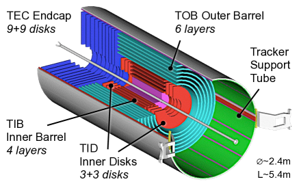
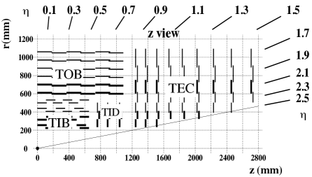
The SST, shown in Figure 1, covers the radial range between and around the LHC interaction point. The barrel region () is split into a Tracker Inner Barrel (TIB) made of four detector layers, and a Tracker Outer Barrel (TOB) made of six detector layers. The TIB is complemented by three Tracker Inner Disks per side (TID). The forward and backward regions () are covered by nine Tracker End-Cap (TEC) disks per side. In some of the layers and in the innermost rings, special stereo modules (Fig. 1, right panel) are used to build double sided assemblies able to provide three-dimensional position measurement of the charged particle hits.
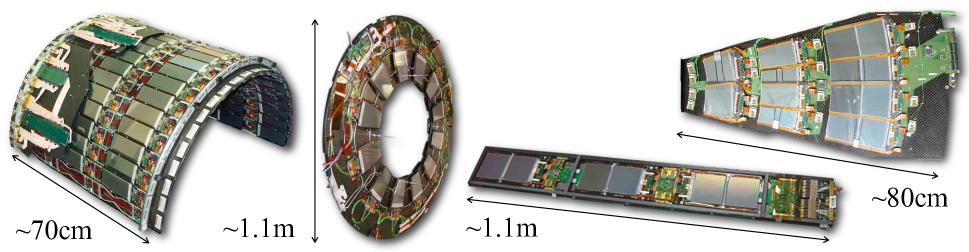
The SST is made up of relatively small carbon fiber assemblies supporting several modules to ease the handling and the mounting. These substructures are fully equipped with cooling and readout electronics to allow for stand-alone tests to be performed. This modularity has been the key-factor for the successful assembly of the huge number of Si-strip modules modules and all other ancillary components into the final detector. The following subdetector-dependent substructures can be found in the SST (Fig. 2): the TIB is split into 16 half cylinder shells each holding 135 to 216 modules; the TID is structured in rings per disk, each designed to support 40 or 48 modules; the TOB is made of 688 rods, drawer-like structures providing support for 6 or 12 modules; and the TECs are made up of petals per endcap, each holding 17 to 28 modules. During each stage of the assembly, every single component is verified. Optical links are checked by measuring the output level of an auxiliary signal issued by the readout chips and modules are checked using pedestal and noise data at full bias () to spot high voltage issues and bad channels cc ; smersi .
Once the substructures were completed, system-wide tests were performed for which cooling was provided as in final CMS operating conditions. Temperature probes mounted on the modules are effective for identifying cooling circuit problems palla . In many cases, a cosmic ray setup was implemented to measure the S/N ratio for MIPs and to perform track reconstruction exercises, so to verify the overall mechanical precision at the sub-millimeter level.
During 2006 all substructures were assembled to create the main subsystems in regional integration centers. Finally the tracker subsystems were installed in the Tracker Support Tube at the CERN Tracker Integration Facility (TIF) between fall ’06 and March ’07. The tracker quality was excellent. The total fraction of bad channels was found to be 0.21%: 0.07% due to module failures, 0.05% due to bad optical links and 0.09% of bad isolated channels, mostly preexisting problems. The assembly procedures and the stringent quality control tests have been proved to be sound as the integration process caused almost no new defects.
Once the assembly of the SST was complete, it was possible to evaluate the material budget by introducing into the detector simulation all the last-minute details added during the construction. The total thickness as a function of reaches a maximum of about 1.8 around (Fig. 3). This is because of the presence of TIB and TID services in this region, which contribute significantly to the overall material budget.
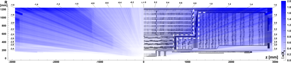
TIB and TID are the most challenging subsystems in terms of volumetric density of channels (in units of channels per m3: TIB 2.2, TID 1.1, TOB 0.52, TEC 0.35) yielding a very large number of service connections in a very small space. This resulted in the previously discussed material budget issue and in difficulties to integrate the services in the limited room allocated.
In December ’07 the SST was installed underground in CMS and the full cabling and piping was completed in March ’08. Unfortunately two serious hardware failures of the cooling system serving the tracker (November ’07 and May ’08) prevented the checkout activities from being performed as scheduled, i.e., immediately after the installation. The entire cooling system needed to be refurbished and was available in June ’08. In the 2008 LHC run, the SST will be conservatively operated at about C instead of at the design temperature of C; in any case, the latter is only required at design luminosity. During the 2008/2009 LHC shutdown the cooling system will be commissioned for cold operations.
II COMMISSIONING
Immediately after the finalization of the assembly at the TIF, an extensive testing program know as the “Slice Test” was carried out. It consisted of cooling, powering and reading out approximately 15% of the entire SST. A scintillator-based trigger permitted 5 million cosmic muon events to be collected at a rate of about 5Hz, filtering out low momentum muons by means of a -thick lead shield placed on the bottom scintillator. The Slice Test allowed the first experience to be gained on commissioning, safety, controls, monitoring, data management, track reconstruction and alignment tif .
After the installation within CMS and once the cooling system was available, the SST joined CMS operations. A cosmic global run without magnetic field took place from 7 to 14 July ’08. The test was very important for CMS: the SST readout makes up approximately of the entire DAQ system. Despite the tight schedule for the first round of commissioning, the SST performance is remarkable. The SST was smoothly read out within the global CMS DAQ and several million events were collected. of the SST modules were switched on (technical issues prevents the endcap on the side from being used) and, of those, around 93% passed the testing procedures first time. The vast majority of the small number of modules excluded from this first global run will be simple to recover. In fact, the following subsequent more detailed commissioning performed before the closure of CMS in fall ’08, certified that the fraction of bad modules in the entire SST is below .
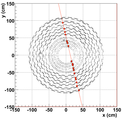
Cosmic muon tracks have been observed in the global run: an example is shown in Figure 4.
III CALIBRATION HIGHLIGHTS
The optimization of the SST depends on several calibration steps tif . The most relevant are briefly described here.
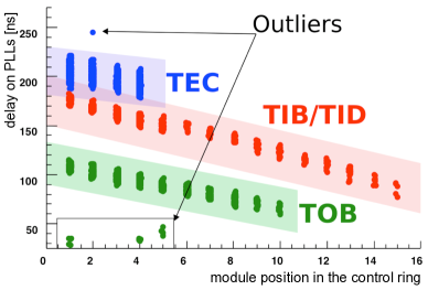
The SST dimensions and cable/fiber lengths imply non negligible timing differences compared to the LHC bunch-crossing period and the detector shaping time. Each module needs to be synchronized to compensate for path differences of control signals (and for any electronics delay) as shown in Figure 5, left panel, where the delays set on the programmable delay unit of each module is plotted against the number of upstream controller chips. In fact, to limit the number of optical links, the control circuit is implemented by daisy-chaining several controller chips introducing a delay that needs to be compensated for.
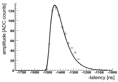
The analogue signal optimization is another fundamental calibration step, to be obtained by setting up the working point parameters of the front-end chips and the downstream optical chain. Among these, one of the most important is the configuration of the front-end chips with the appropriate latency value that, once a L1 trigger is issued, makes each module send the data samples corresponding to the correct bunch crossing to the FEDs (the SST ADC boards). The result of the corresponding procedure (latency scan) are shown in Figure 5, right panel: the CR-RC pulse shape is reconstructed by scanning a range of possible latency values in steps of and taking as the optimal setting the closest value to the maximum amplitude. In addition a fine tuning within a single bunch crossing will compensate for time-of-flight effects tof .
IV CONCLUSIONS
The SST has been built, installed and read out within CMS. Commissioning procedures, online and offline tasks have been demonstrated to work well. Final commissioning and checkout procedures have demonstrated that the SST quality is excellent with more than of good modules. The SST is ready to deliver optimally reconstructed tracks.
References
- (1) S. Chatrchyan et al. [CMS Collaboration], JINST 3 S08004 (2008).
- (2) CMS Collaboration, CERN-LHCC/98-6 (1998); CMS Collaboration, CERN-LHCC/2000-16 (2000).
- (3) M. Krammer [CMS Tracker Collaboration], Nucl. Instrum. Meth. A 582 (2007) 766.
- (4) C. Civinini [CMS Tracker Collaboration], Nucl. Instrum. Meth. A 579 (2007) 726.
- (5) S. Mersi [CMS Tracker Collaboration], Nucl. Phys. Proc. Suppl. 177-178 (2008) 318.
- (6) F. Palla [CMS Tracker Collaboration], Nucl. Instrum. Meth. A 572 (2007) 104.
- (7) C. Delaere [CMS Collaboration], CERN-CMS-CR-2008-002.
- (8) C. Delaere et al., CERN-CMS-NOTE-2008-007.