email: ias@astro.livjm.ac.uk
RISE: a fast-readout imager for exoplanet transit timing
Abstract
By the precise timing of the low amplitude (0.005 - 0.02 magnitude) transits of exoplanets around their parent star it should be possible to infer the presence of other planetary bodies in the system down to Earth-like masses. We describe the design and construction of RISE, a fast-readout frame transfer camera for the Liverpool Telescope designed to carry out this experiment. The results of our commissioning tests are described as well as the data reduction procedure necessary. We present light curves of two objects, showing that the desired timing and photometric accuracy can be obtained providing that autoguiding is used to keep the target on the same detector pixel for the entire (typically 4 hour) observing run.
keywords:
robotic telescopes, exoplanets, timing, astronomical instrumentation1 INTRODUCTION
The Liverpool Telescope[1] (LT) is a 2.0 metre fully robotic telescope. The telescope Acquisition & Guidance (A&G) unit can host up to five instruments[2] with the beam able to be directed to one of four side ports via a folding mirror, or, with the folding mirror removed from the beam, to a straight through port. The rapid time to switch between instruments ( seconds) combined with automated observing scheduling[3] means that the telescope is well suited to time variable (on timescales of minutes to years) and rapid reaction astronomy.
A key science goal of the Liverpool Telescope is the discovery of Earth mass exoplanets (i.e. planets outside our own solar system). Two techniques are pursued. The first is via participation in the coordinated followup programmes[4] of galactic bulge microlensing events where small anomalies in the light curves act as signatures of planets orbiting the lens star. An example of the application of this technique in which the LT was involved was the recent discovery of a Jupiter/Saturn solar system analogue[5]. The second technique involves the precise timing of transits of known Jupiter-like exoplanets around their parent star, looking for deviations from the expected ephemeris due to the influence of other (unseen) planets in the system perturbing the orbit. It is this second technique which is the subject of this paper, which describes the construction of a moderately wide field, fast-readout CCD imager for the Liverpool Telescope known as RISE (Rapid Imaging Search for Exoplanets). In this paper we will give a brief overview of the science driver for the instrument and the requirements it places on the design, followed by details of its design and construction. We will also discuss the data reduction procedure for the instrument, and give the results of our commissioning tests.
2 SCIENCE REQUIREMENTS
The detection of exoplanets is currently of great topical interest in astronomy. As technology and techniques progress the main emphasis is naturally moving towards the detection of low mass planets. These objects are difficult to detect by direct means and it is likely that we will have to wait for an ELT to image the first Earth analogue system. However, in the mean time, a number of techniques are being used to indirectly detect super-earth massed planets. For an eclipsing system, the idea of using timing residuals to infer the presence of a third, usually lower mass, body is not a new one, going back to the discovery of the outer planets of our own solar system. Recent calculations[6, 7] show that a low mass planet moving in a resonance orbit can alter the transit times of a hot Jupiter planet by sec for periods of 40 days or more.
Typical transiting exoplanets so far discovered [8, 9, 10, 11] have magnitudes in the range , with amplitudes of 5-20 mmag and durations of 1-3 hours. It can be seen that photometry at the few milli-magnitude level is therefore required. Often signals such as this are dominated by systematic noise sources. To overcome this it is necessary to image as many comparison stars as possible with similar brightness to the target star. Our field of view requirement ( arcminutes) was therefore driven by the maximum field of view available at a side port of the LT A&G box.
On a 2-metre telescope the target brightness implies exposure times of 1-10 seconds to obtain the required SNR for milli-mag photometry. This implies a requirement for a readout time of less than 1 second in order that close to the maximum number of data points (i.e. total number of photons) is collected over the fixed duration of the transit.
3 INSTRUMENT DESIGN AND BUILD
3.1 Optical design
The LT has a plate scale of microns/arcsecond, meaning that to cover a arcminute field of view a simple focal plane CCD would be mm. While such CCD’s do exist, they are expensive and with the large number of pixels implied by the large detector area, generally slow to readout with low noise. It was therefore decided to use a smaller, frame transfer CCD combined with a field condensing system to achieve the combination of field of view and readout speed.
The camera selected was a Andor DW435 model. This uses an an E2V CCD47-20 back illuminated, frame transfer CCD which has 1024 x 1024 pixel light sensitive region (LSR). Each pixel is 13.0 x 13.0 microns. Used in direct imaging mode such a device would therefore yield a field of view of 2.3 x 2.3 microns with a pixel scale of 0.13 arcseconds per pixel. A condensing system with a linear magnification of was therefore required.
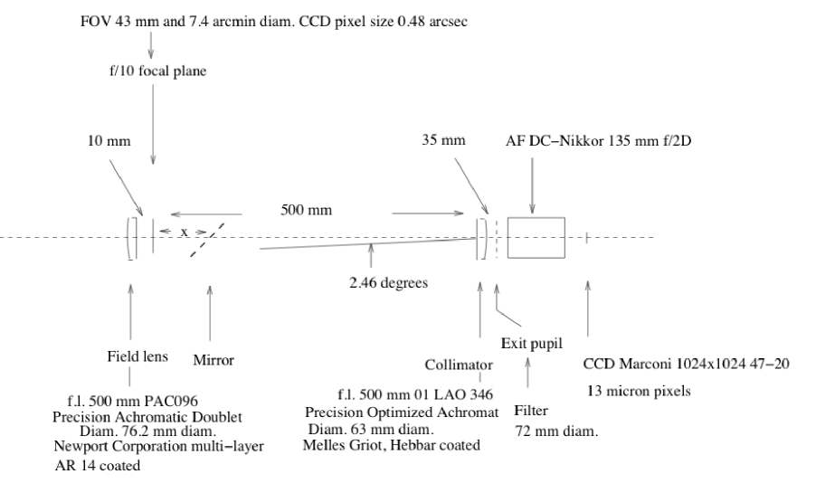
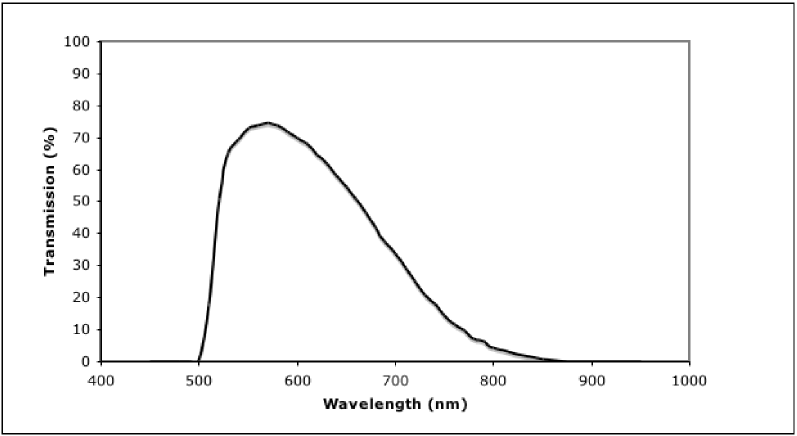
The overall aim of the optical design (Figure 1) of the field condensing chain was therefore to achieve a 7.4 arcmin diameter unvignetted field-of-view with imaging quality better than the CCD pixel size (0.48 arcsec diameter) when projected on to the sky. This is achieved with simple off-the-shelf optics which includes a 500 mm focal length, 63 mm diameter, Melles Griot “Optimized Achromat” as a collimator and a Nikkor 135 mm focal length f/2D commercial compound lens as the camera. A Newport “Precision Achromatic Doublet” field lens, just inside the telescope’s focal plane, places the telescope’s exit pupil on to a filter between the collimator and camera. This filter is of a similar design to that built for the LT RINGO polarimeter[12], in this case constructed from 2mm Schott KG5 bonded to 3mm Schott OG515 (Figure 2)
The transmission surfaces of the two achromatic lenses are coated with three-layer anti-reflection coatings to minimize losses and ghosts. After the field lens the beam is reflected by a 45 degree plane mirror in an adjustable holder to permit the field-of-view to be centred precisely on the CCD in the camera’s focal plane as well as permitting the exit pupil, after the collimator, to be centred on the optical axis. It was found in commissioning (Section 4) that the optical aims were easily achieved, in fact the useful field-of-view approaches 9 arcmin diameter even though vignetted somewhat beyond the design value of 7.4 arcmin.
3.2 Mechanical Design
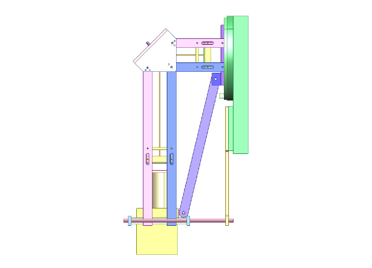
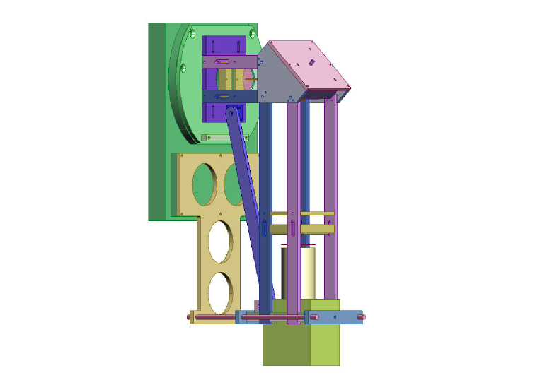
The mechanical design of the instrument (Figures 3 & 4) was driven by the off-the-shelf nature of the optics used. The collimator lens has a 500mm focal length; this made the instrument too long to be stable without a fold mirror. The fold mirror brings the optical axis of the instrument alongside the Acquisition and Guidance box of the telescope, thereby affording further mechanical brace points. A diagonal bar was fitted spanning the length of the instrument to eliminate sag through the 90 degree fold. The bottom of the instrument was then clamped to lower part of the A&G box to eliminate ‘sway’. Due to the physical size of this instrument weight was going to be a concern, so it was decided to use Aluminum Alloy 5083 H0 for its light weight yet strong tensile strength.
There are two lenses in this instrument, a field lens (Newport PAC096) and a collimator lens (Melles Griot LAO 346). The field lens is mounted approximately 10mm inside the focal plane of the telescope in an aluminum block, using an O ring mounting to allow for the effects of temperature changes at site. The position of this aluminum block can be adjusted +/- 15mm. Then a fold mirror is mounted 150mm from the telescope focal plane, this mirror has a purpose built kinematic mount and can be adjusted about its centre point easily after the entire instrument has been assembled, facilitating alignment. Mounted 350mm further along the optical path is the collimator lens in a similar mount to the field lens with the same amount of adjustment to allow the focus to be set accurately. Finally the Camera (Andor DW435) with bayonet mounted camera lens (Nikkor 135mm) is mounted within a Tufnol plate to electrically insulate it from the rest of the instrument.
3.3 CCD system
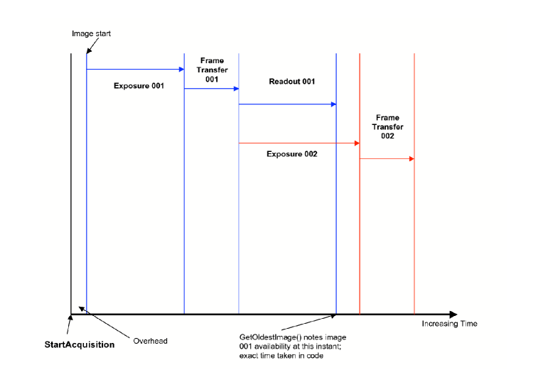
The Andor CCD camera was connected to an Instrument Control Computer (ICC) via a standard PCI connection. Power for the CCD system is drawn from this connection via a supplemental power connection to the PCI card from the host system. The CCD is constructed with a light insensitive (LISR) 1024x1024 pixel region adjacent to the LSR pixel array of the CCD. This acts as a buffer to hold data being moved from the LSR. This is the frame-transfer aspect of the CCD, and means that when one image acquisition has completed on the LSR, it is immediately shunted to the LISR. This allows another image to start acquiring very quickly, hence the increased time resolution of the camera. This is in contrast to a standard CCD camera, where the image must be read out before another is taken. Once an acquisition has started a series of images is acquired by the camera resulting in an exposure-frame transfer-readout cycle (Figure 5.)
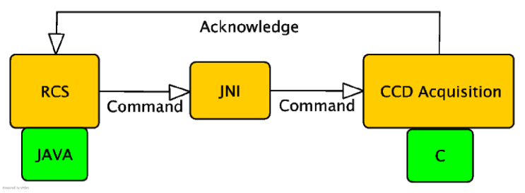
The software setup for the RISE camera is broken down into two components: the CCD control system and the CCD acquisition system. The CCD image acquisition system (IAS) is responsible for instructing the CCD hardware to acquire images, and control temperature and onboard acquisition characteristics. This is written in C and makes use of the Andor Linux SDK, allowing camera control software to be written relatively quickly. The camera control links the C-level acquisition system to the Java based robotic commands system, which issues the acquisition commands e.g. calibration set (Figure 6). The Java and C implementations are linked by the Java Native Interface (JNI), allowing the Java based Robotic Control System (RCS) to call the C-based acquisition routines.
Due to the nature of the image acquisition software the data rate is very high for short exposures. Data can be acquired in 1x1 or 2x2 binning modes, with minimum exposure cycle times of sec and sec respectively; thus the maximum data generation capacity can be Gbytes per hour for a 1x1 data run or Gbytes per hour in 2x2 mode. Another side effect of the high data is the need to run the acquisition process in isolation from the the ICS. The usual LT method of acquisition is to take an image and return an acknowledgment to the RCS between each image. However, to do so in this case would create timing delays and introduce an unusual level of packet traffic between the IAS and the RCS. The solution to this is to yield control of the instrument to the IAS and send an acknowledge at the end of a long run.
Bias, flat and science frames are taken through two modes of acquisition: twilight calibrate and multrun. Since there is no shutter on the CCD, it can be difficult to acquire a bias image. This must be achieved manually by taking zero second exposures with the light path to the CCD obstructed. Dark frames are taken in a similar fashion with the ‘multrun command’. Flats are taken via the ‘twilight calibrate’ command which adapts the exposure time to achieve a similar number of counts on each flat image based on the median count in the previous image. Finally, the ‘multrun’ command takes a series of images in frame transfer mode. The number of images required is set along with the exposure time. The acquired data is stored locally on the ICC before being transferred back to LJMU next day, where it is made available via staging on a webserver.
4 Commissioning
RISE was fitted to the Liverpool Telescope in February 2008. Setup was relatively straight forward. The instrument was fitted to the telescope without the CCD camera. A test card was clamped to the field lens holder and the holder was adjusted to the focal point of the telescope. A 1 metre focal length telescope (set to infinity) was then positioned where the camera would eventually sit and the collimator lens was adjusted until the test card could be viewed in focus. The test card was removed and the field lens adjusted away from the focal plane to keep any dust particles out of focus. The mirror was then roughly adjusted by eye to bring all the optical components concentric within the instrument. The camera was then fitted and images taken of the inside of the enclosure. A combination of small adjustments of the telescope fold mirror in the A&G box and the fold mirror within the instrument itself were then made to centre the image.
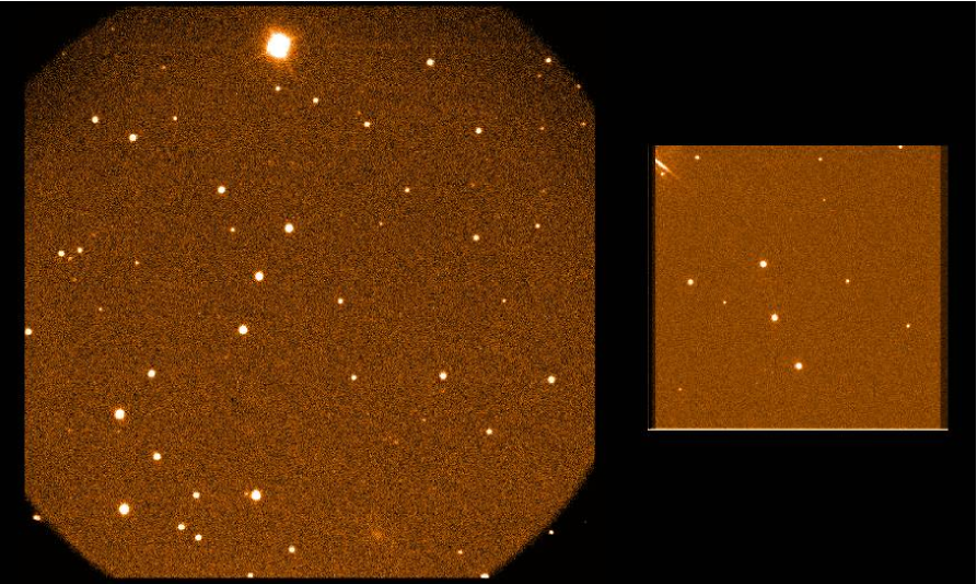
On sky commissioning took place over the period 20-23rd February 2008. The field of view (with some vignetting in the corners) was found to be 9.4 x 9.4 arcminutes, corresponding to a pixel scale of 0.55 arcsec/pixel (Figure 7). No significant variation in point spread function across the field could be detected. The detector system read-noise was measured at 10 electrons rms, and the gain as 2.4 electrons/count. Linearity testing showed good performance up to the ADC conversion limit to 65,000 counts with 1x1 binning and around 40,000 counts with 2x2 binning. With the short exposure times used for the instrument no significant dark current could be detected.
5 data reduction
The reduction of data to milli-mag accuracies is a complex task, and requires a good understanding of the systematic errors. At present our data reduction procedures are still at an experimental stage, although we can already demonstrate high quality photometry and timing results (Figure 8).
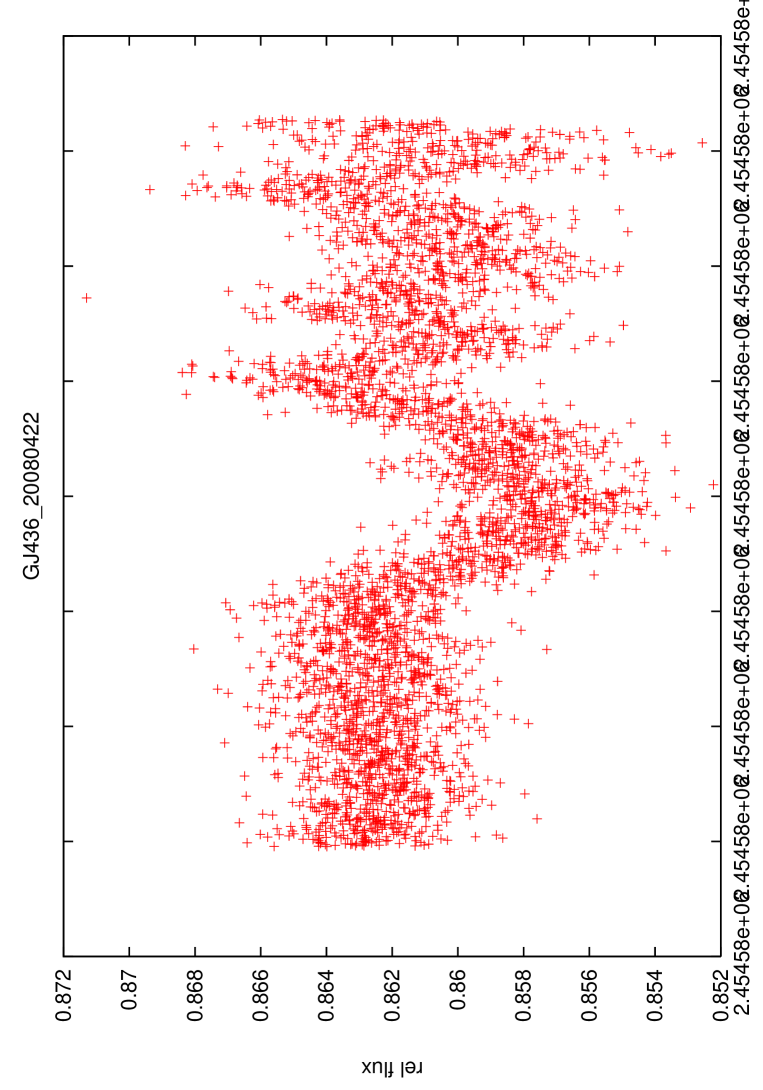
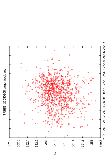
The initial stages the raw images are first put through a python/pyraf script that updates the headers that are needed at the reduction or lightcurve fitting stage, including the heliocentric Julian date and airmass (calculated from DATE-OBS, RA and DEC), plus other instrument characteristics such as the gain, read-noise and filter. Due to the instrument not having a shutter we try both bias images and bias strips to debias the images. Flat fielding is also tricky. We currently do not understand how the flat field structure changes during the course of a night (due to scattered light in the telescope and optics) and therefore we prefer not to flat field in cases where autoguiding is stable. This is because the ratio of the stars fluxes on the chip will stay constant and flat fielding effects will be removed to first order during sky subtraction anyway. If however there is some drift (e.g. due to lack of an appropriate guide star) flat fielding must be used to remove some (but not all) of the systematic effects. An example of this is shown in Figure 9 where autoguiding was lost half way through the run (Figure 10) - the detrimental effect on the light-curve is obvious.
Aperture photometry is performed on the images using IRAF/daophot via a python/pyraf script that uses a list of apertures to calculate the relative flux of the target star (given a list of reference stars coordinates) and the respective errors. Typically an aperture of 10 pixels is used (in 2x2 binning mode). Following this the lightcurves are then normalized using an airmass (or time) function and a model is fitted to the lightcurves according to an analytic formula[13] using a Monte Carlo Markov Chain code with suitable priors on known stellar and orbital parameters. This allows us to calculate the radius, inclination and central transit times. It is the variation of these central transit times from the predicted ephemeris that will provide evidence of a third body.


6 CONCLUDING REMARKS
RISE was a fast-track instrument for the Liverpool Telescope, which was designed, built and commissioned within 1 year of the initial science requirement being identified. Although work is still underway to better understand the effect of scattered light on the observations, it is already clear that the timing precision obtainable is sufficient to carry out our programme of transit followup, which has therefore begun routine data taking. In addition we are pleased to note that it is also attracting interest from other science users of the telescope attracted by its low overheads for timing experiments and its relatively wide field.
Acknowledgements.
We thank the staff of the QUB Physics workshop for their excellent work in constructing RISE. The Liverpool Telescope is operated on the island of La Palma by Liverpool John Moores University in the Spanish Observatorio del Roque de los Muchachos of the Instituto de Astrofisica de Canaries with financial support from the UK Science and Technologies Facilities Council.References
- [1] Steele, I. A., Smith, R. J., Rees, P. C., Baker, I. P., Bates, S. D., Bode, M. F., Bowman, M. K., Carter, D., Etherton, J., Ford, M. J., Fraser, S. N., Gomboc, A., Lett, R. D. J., Mansfield, A. G., Marchant, J. M., Medrano-Cerda, G. A., Mottram, C. J., Raback, D., Scott, A. B., Tomlinson, M. D., and Zamanov, R., “The Liverpool Telescope: performance and first results,” in [Proceedings of the SPIE, Volume 5489, pp. 679-692 (2004). ], Oschmann, J. M., ed., 679–692 (Oct. 2004).
- [2] Mottram, C. J., Steele, I. A., and Morales, L., “Design of low cost and reliable instrumentation for robotic telescopes,” in [Ground-based Instrumentation for Astronomy. Edited by Alan F. M. Moorwood and Iye Masanori. Proceedings of the SPIE, Volume 5492, pp. 677-688 (2004). ], Moorwood, A. F. M. and Iye, M., eds., 677–688 (Sept. 2004).
- [3] Fraser, S. and Steele, I. A., “Robotic telescope scheduling: the Liverpool Telescope experience,” in [Optimizing Scientific Return for Astronomy through Information Technologies. Edited by Quinn, Peter J.; Bridger, Alan. Proceedings of the SPIE, Volume 5493, pp. 331-340 (2004). ], Quinn, P. J. and Bridger, A., eds., Presented at the Society of Photo-Optical Instrumentation Engineers (SPIE) Conference 5493, 331–340 (Sept. 2004).
- [4] Burgdorf, M. J., Bramich, D. M., Dominik, M., Bode, M. F., Horne, K. D., Steele, I. A., Rattenbury, N., and Tsapras, Y., “Exoplanet detection via microlensing with RoboNet-1.0,” PLANSS 55, 582–588 (Apr. 2007).
- [5] Gaudi, B. S., Bennett, D. P., Udalski, A., Gould, A., Christie, G. W., Maoz, D., Dong, S., McCormick, J., Szymański, M. K., Tristram, P. J., Nikolaev, S., Paczyński, B., Kubiak, M., Pietrzyński, G., Soszyński, I., Szewczyk, O., Ulaczyk, K., Wyrzykowski, Ł., DePoy, D. L., Han, C., Kaspi, S., Lee, C.-U., Mallia, F., Natusch, T., Pogge, R. W., Park, B.-G., Abe, F., Bond, I. A., Botzler, C. S., Fukui, A., Hearnshaw, J. B., Itow, Y., Kamiya, K., Korpela, A. V., Kilmartin, P. M., Lin, W., Masuda, K., Matsubara, Y., Motomura, M., Muraki, Y., Nakamura, S., Okumura, T., Ohnishi, K., Rattenbury, N. J., Sako, T., Saito, T., Sato, S., Skuljan, L., Sullivan, D. J., Sumi, T., Sweatman, W. L., Yock, P. C. M., Albrow, M. D., Allan, A., Beaulieu, J.-P., Burgdorf, M. J., Cook, K. H., Coutures, C., Dominik, M., Dieters, S., Fouqué, P., Greenhill, J., Horne, K., Steele, I., Tsapras, Y., Chaboyer, B., Crocker, A., Frank, S., and Macintosh, B., “Discovery of a Jupiter/Saturn Analog with Gravitational Microlensing,” Science 319, 927– (2008).
- [6] Holman, M. J. and Murray, N. W., “The Use of Transit Timing to Detect Terrestrial-Mass Extrasolar Planets,” Science 307, 1288–1291 (Feb. 2005).
- [7] Agol, E., Steffen, J., Sari, R., and Clarkson, W., “On detecting terrestrial planets with timing of giant planet transits,” MNRAS 359, 567–579 (May 2005).
- [8] Cameron, A. C., Bouchy, F., Hébrard, G., Maxted, P., Pollacco, D., Pont, F., Skillen, I., Smalley, B., Street, R. A., West, R. G., Wilson, D. M., Aigrain, S., Christian, D. J., Clarkson, W. I., Enoch, B., Evans, A., Fitzsimmons, A., Fleenor, M., Gillon, M., Haswell, C. A., Hebb, L., Hellier, C., Hodgkin, S. T., Horne, K., Irwin, J., Kane, S. R., Keenan, F. P., Loeillet, B., Lister, T. A., Mayor, M., Moutou, C., Norton, A. J., Osborne, J., Parley, N., Queloz, D., Ryans, R., Triaud, A. H. M. J., Udry, S., and Wheatley, P. J., “WASP-1b and WASP-2b: two new transiting exoplanets detected with SuperWASP and SOPHIE,” MNRAS 375, 951–957 (Mar. 2007).
- [9] Pollacco, D., Skillen, I., Collier Cameron, A., Loeillet, B., Stempels, H. C., Bouchy, F., Gibson, N. P., Hebb, L., Hébrard, G., Joshi, Y. C., McDonald, I., Smalley, B., Smith, A. M. S., Street, R. A., Udry, S., West, R. G., Wilson, D. M., Wheatley, P. J., Aigrain, S., Alsubai, K., Benn, C. R., Bruce, V. A., Christian, D. J., Clarkson, W. I., Enoch, B., Evans, A., Fitzsimmons, A., Haswell, C. A., Hellier, C., Hickey, S., Hodgkin, S. T., Horne, K., Hrudková, M., Irwin, J., Kane, S. R., Keenan, F. P., Lister, T. A., Maxted, P., Mayor, M., Moutou, C., Norton, A. J., Osborne, J. P., Parley, N., Pont, F., Queloz, D., Ryans, R., and Simpson, E., “WASP-3b: a strongly irradiated transiting gas-giant planet,” MNRAS 385, 1576–1584 (Apr. 2008).
- [10] Wilson, D. M., Gillon, M., Hellier, C., Maxted, P. F. L., Pepe, F., Queloz, D., Anderson, D. R., Collier Cameron, A., Smalley, B., Lister, T. A., Bentley, S. J., Blecha, A., Christian, D. J., Enoch, B., Haswell, C. A., Hebb, L., Horne, K., Irwin, J., Joshi, Y. C., Kane, S. R., Marmier, M., Mayor, M., Parley, N., Pollacco, D., Pont, F., Ryans, R., Segransan, D., Skillen, I., Street, R. A., Udry, S., West, R. G., and Wheatley, P. J., “WASP-4b: A 12th Magnitude Transiting Hot Jupiter in the Southern Hemisphere,” ApJ 675, L113–L116 (Mar. 2008).
- [11] Anderson, D. R., Gillon, M., Hellier, C., Maxted, P. F. L., Pepe, F., Queloz, D., Wilson, D. M., Collier Cameron, A., Smalley, B., Lister, T. A., Bentley, S. J., Blecha, A., Christian, D. J., Enoch, B., Hebb, L., Horne, K., Irwin, J., Joshi, Y. C., Kane, S. R., Marmier, M., Mayor, M., Parley, N. R., Pollacco, D. L., Pont, F., Ryans, R., Ségransan, D., Skillen, I., Street, R. A., Udry, S., West, R. G., and Wheatley, P. J., “WASP-5b: a dense, very hot Jupiter transiting a 12th-mag Southern-hemisphere star,” MNRAS , L49+ (Apr. 2008).
- [12] Steele, I. A., Bates, S. D., Carter, D., Clarke, D., Gomboc, A., Guidorzi, C., Melandri, A., Monfardini, A., Mottram, C. J., Mundell, C. G., Scott, A. B., Smith, R. J., and Swindlehurst, J., “RINGO: a novel ring polarimeter for rapid GRB followup,” in [Ground-based and Airborne Instrumentation for Astronomy. Edited by McLean, Ian S.; Iye, Masanori. Proceedings of the SPIE, Volume 6269, pp. 62695M (2006). ], Presented at the Society of Photo-Optical Instrumentation Engineers (SPIE) Conference 6269 (July 2006).
- [13] Mandel, K. and Agol, E., “Analytic Light Curves for Planetary Transit Searches,” ApJ 580, L171–L175 (Dec. 2002).