Forces on a nanoparticle in an optical trap
Abstract
Forces on a nanoparticle in an optical trap are analysed. Brownian motion is found to be one of the major challenges to trap a nanoparticle. Accordingly, suitable spatial electric field distribution of laser beam is suggested to enhance the trapping force on a nanoparticle. Theoretical analysis is carried out to obtain conditions for stable optical trap by incorporating the temperature variation at large laser intensities. Numerical analysis is made for single quantum dot of CdS in buffer solution irradiated by an Nd:YAG laser.
pacs:
87.80.Cc,05.40.-a, 61.46.Df, 68.65.Hb, 52.38.BvI Introduction
Single laser beam optical tweezers are widely employed for trapping and manipulation of micrometer sized particles. It finds variety of novel applications including biomedical measurements bio , quantum computation babcock , single molecule nonlinear optical measurements nlo , etc. Of late, availability of sophisticated instruments made it possible to realise optical manipulation of particles with force and position resolutions of 0.1 pN and 0.1 nm stable . With appropriate design and usage of modern electro-optic devices such as spatial light modulator (SLM), piezo stages and high resolution charge coupled devices (CCD), manipulation of optical beam with custom designed spatial profile is possible grier ; dufresne ; bukusoglu ; zhao .
Grier and his group grier have used computer-generated holograms with SLM to create arbitrary three-dimensional configurations of single-beam optical traps that are useful for capturing, moving, and transforming mesoscopic objects in 3-dimensional holographic optical tweezers (3D-HOT). Through a combination of beam-splitting, mode-forming and adaptive wavefront correction, HOT can exert precisely specified and characterized forces and torques on objects ranging in size from a few nanometers to hundreds of micrometers. Dufresne et al dufresne created arbitrary configuration of optical tweezers using computer generated diffractive optical elements with appropriate design to eliminate stray lights. Recently, interest has been shown to construct optical traps with custom designed laser profiles bukusoglu ; zhao ; hoogenboom ; svobo ; sugi ; parkin ; schnelle ; macdonald ; nano . Optical tweezers with a haptic device and XYZ piezo scanner to manipulate the position of microspheres are also used bukusoglu . Zhao et al zhao used highly focussed hollow Gaussian beams to trap and manipulate Rayleigh particles. Hoogenboom et alhoogenboom have developed a method to create a pattern of wide variety of colloidal particles of size as small as 79nm with a resolution below the particle size using optical tweezers. Today, one of the major interests in the field of optical trapping has been to manipulate smaller nanoscale objects. For metallic substances, the trapping of a single 36-nm diameter gold particle has been achieved svobo and a 40-nm diameter gold particle was employed as a probe of scanning near-field optical microscope (SNOM) sugi . There are many reports which make use of arbitrary custom designed laser profiles such as non-circular Gaussian LG02 mode parkin , torroidal shape trap schnelle rotating interference pattern macdonald establishing the usefulness of the arrangement to trap transparent dielectric nano-particles successfully.
The major challenges encountered in trapping nano-particle include (i) Brownian motion arising due to thermal force and (ii) cluster formation. In dual beam optical tweezers two types of temperature control methods were proposed by Mao et al thermal . They could overcome the problem of heat convection at high intensities of laser using a circulation method. On the other hand cluster formation occurs when many particles are trapped simultaneously giving rise to larger finding binding forces nano . In our opinion, a detailed theoretical understanding on nano-particle trapping with optical tweezers is still in its infancy and warrants attention. Present paper, makes an attempt to understand the problems associated with trapping a nano-particle and suggests a suitable spatial profile of laser to enhance the trapping force. We have examines trapping conditions for various spatial profiles of lasers viz., Hermite Gaussian (HG), Laguerre Gaussian (LG) and Custom designed spatial profiles, giving due considerations to gradient, scattering and thermal forces. A comparison of the results has been made which suggests the suitability of custom designed modes over the HG and LG modes.
II Theory
Optical tweezers take advantage of radiation pressure exerted on a micro-nano particle to trap it in an electromagnetic potential well. Radiation pressure is generated by tightly focussing laser beam with a large numerical aperture (NA ) condensing lens or by using a combination of aspheric lenses. The radiation pressure near the focus arises due to (i) scattering force which is proportional to the intensity of light and is on the same direction as that of the incident light and (ii) gradient force which is proportional to the spatial gradient of light intensity. For axial stability of a single beam trap, the ratio of backward gradient force to forward scattering force should be greater than unity. As an additional trapping condition for Rayleigh particle, we also need to take into account the thermal forces. Apart from this precaution must be taken to avoid cluster formation under suitable illumination conditions.
In the Rayleigh regime, when the particle size () is very small in comparison to the wavelength (), the scattering force is given by ashkin However when particle density is larger (or when mean free path is smaller) optical binding force also becomes dominant. The reported size of particle trapped using conventional optical tweezers is 50nm to 100m. The lower limitation of size are attributed to the diffraction-limited trap volume, smaller scattering and absorption cross sections and significant Brownian motion due to large thermal energy acquired by the particle. In order to trap particle size much lower than the wavelength of the trap beam, the challenges to be met are (i) diffraction limited optics, (ii) elimination of optical binding forces and (iii) overcoming the forces arising due to Brownian motion of the nanoparticles. Accordingly, significant changes should be made to the conventional optical tweezers design such as holographic optical tweezers grier , haptic beam control bukusoglu , electromagnic coupled plasmonic optical trap grigo or near resonant excitation reso .
Under Rayleigh scattering regime (), when the particle to be trapped is much smaller than the wavelength of the light used to generate radiation pressure, the various forces are calculated by assuming as point dipole scatterers and the focus as a diffraction-limited region. With this approximation the scattering and gradient forces are separated comfortably and can be analyzed independently. The scattering force for a point dipole of size is found to be
| (1) |
where, is refractive index of the medium surrounding the nanoparticle, is the intensity of light used to trap the particle and is the scattering cross section defined as
| (2) |
Here, is the relative refractive index defines as , with being the refractive index of the particle. The gradient force is given by ashkin
| (3) |
with the polarizability () of the particle being
| (4) |
From eqs. (1) and (3), it is evident that the scattering and gradient forces are proportional to and , respectively. In other words, the magnitudes of both the scattering cross section and polarizability become too small to hold the particles inside the trap. Apart from this, to trap a particle of dimension smaller than the wavelength of light, one needs to take extra care of forces arising due to binding of particles and thermal effects. The binding force dominates when the particle mean free path is smaller. However, when the particle density is smaller, the mean free path becomes larger and hence the binding force may be ignored. With recent advances in piezo-stages, one can maintain a relatively stable equilibrium. For Rayleigh particles (of nanometer in size), thermal energy available at room temperature is adequate to dominate the scattering and gradient forces and it becomes impossible to trap the particle. In his celebrated paper, Ashkin ashkin suggested that as an additional condition for trapping the Boltzmann factor “”, with being the potential of the gradient force. Taking into account the thermal conductivity, spot size and the optical absorption coefficient the corresponding thermal force is found to be thermal
| (5) |
where is the Stoke’s friction constant with and as the mass density and kinematic viscosity of the medium, respectively. For a nanoparticle, force arising due to the thermal energy will diffuse the Rayleigh particle. Accordingly, we consider that this force is acting isotropically in all the directions. Since a cw laser is used for trapping particles a equilibrium in temperature is expected to occur. The temperature of the medium / particle is , with is the ambient temperature while the increase in temperature due to trap beam can be calculated from steen
| (6) |
Here, with as the cw laser power, being the reflectivity of the medium while and are the optical absorption coefficient and thermal conductivity of medium, respectively. and are spot radius at beam waist and thickness of the medium, respectively.
For a given cw laser of power 100mW and a diffraction limited spot size of 50m the force arising due to thermal energy is independent of particle size and is calculated to be 0.4 pN at room temperature. This magnitude of force is negligible as compared to the gradient and scattering forces acting on a microparticle. On the other-hand, for a nanoparticle this is significant enough to dominate the scattering and gradient forces. We introduce a dimensionless force parameter to calculate the effective force on a particle by defining
| (7) |
Estimation of immediately gives the condition for the particle to be trapped as stablity . From the above equation, it is clear that when the thermal force dominates, the total force will be less than 1, leading to an unstable trap. In order to overcome this problem of trapping nanoparticles at room temperature, we compare the radiative forces arising from some well known spatial profiles of laser beam with suggested custom designed laser beam profile which is possible using suitable SLM and software code. Accordingly, the radiation pressure on a nanometer sized spherical particle is calculated by assuming three spatial profiles for the electromagnetic field, viz., (i) Hermite Gaussian (HG) (ii) Laguerre Gaussian (LG) and (ii) a Custom designed Gaussian profile (CG). We use standard equations under cylindrical coordinate system to define the radiation profiles as parkin ; stablity
| (8) | |||||
| (9) | |||||
| and | |||||
| (10) |
Here, , is the radius of curvature with being the depth of focus and spot size . are integers defining laser modes. is Hermite Gaussian function of order . is the generalised Laguerre Gaussian of order and index . The intensity of the laser beam may be calculated from
| (11) |
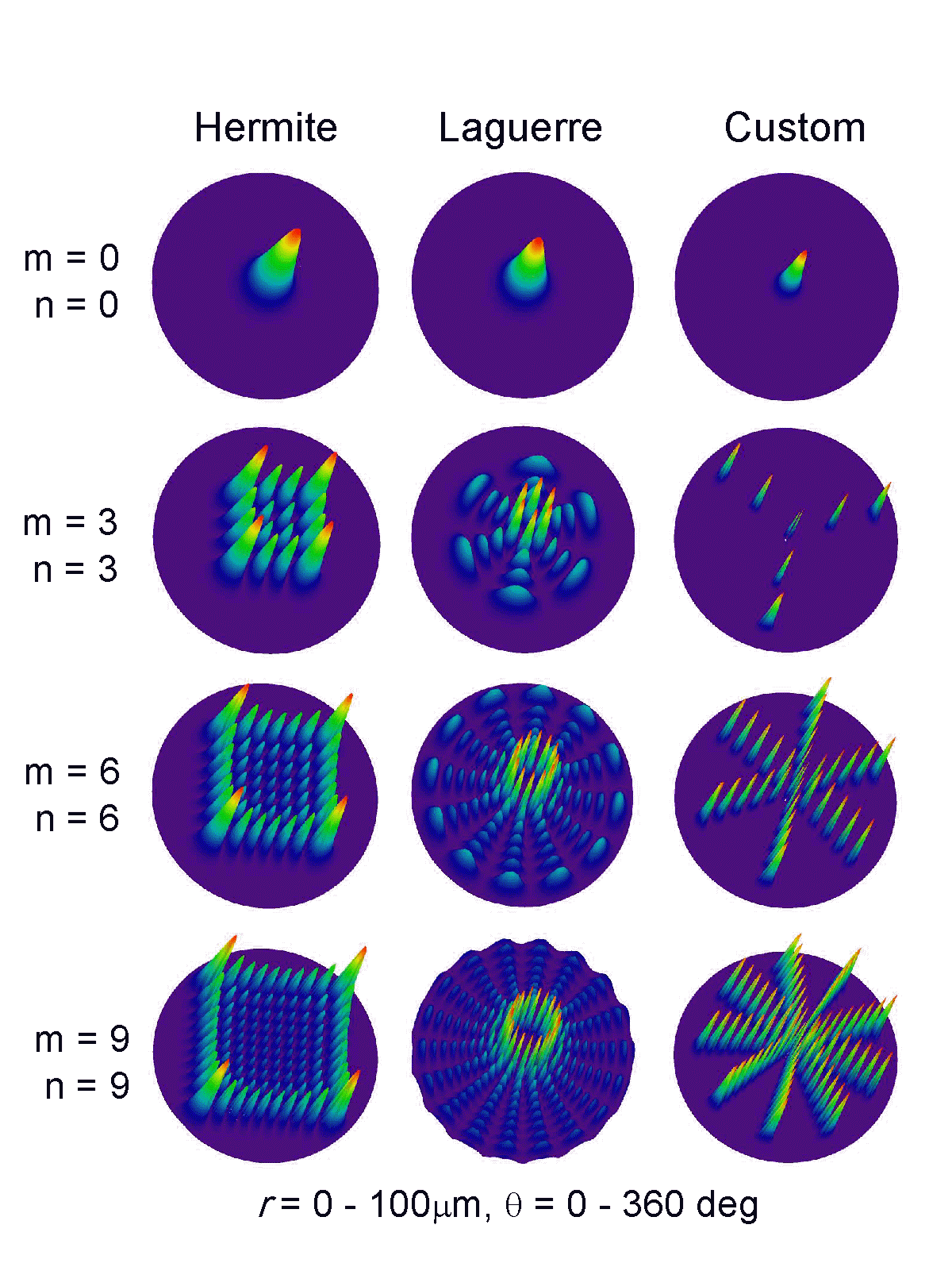
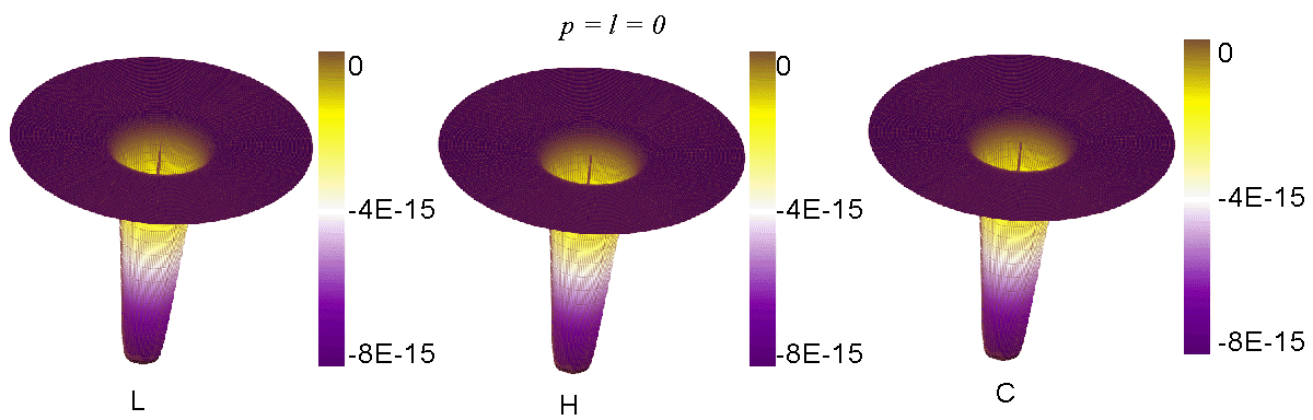
with , representing LG, HG or CG laser profiles, respectively. For , all profiles defined above reduce to TEM00 mode structure as depicted in Figure 1. The figure also shows other profiles obtained for 3, 6 and 9. One can notice from the figure that for higher order modes the beam profile becomes sharper while the individual linewidths of each mode is not a constant. In other words, for higher order modes one can expect sharp rise to the magnitudes of gradient and scattering forces when the number of modes increase. We make use of this feature as a key point to explore the possibility of trapping nanoparticles in a single beam optical trap.
III Results and Discussions
In order to understand the present set of equations for trapping a nanoparticle, we have calculated the net force acting on a semiconductor single quantum dot (SQD) of CdS suspended in a colloid matrix.
The material parameters are: = 5nm, = 1.65, = 1.33. = 97 m/K, = 15 10-5cm-1.
The laser assumed to be Nd:YAG or a diode pumped solid state laser operating at 1.064 m and having an optical power of 100mW.
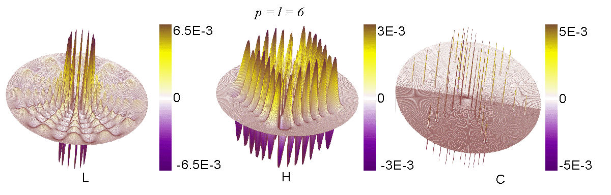
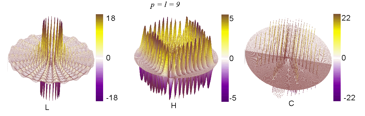
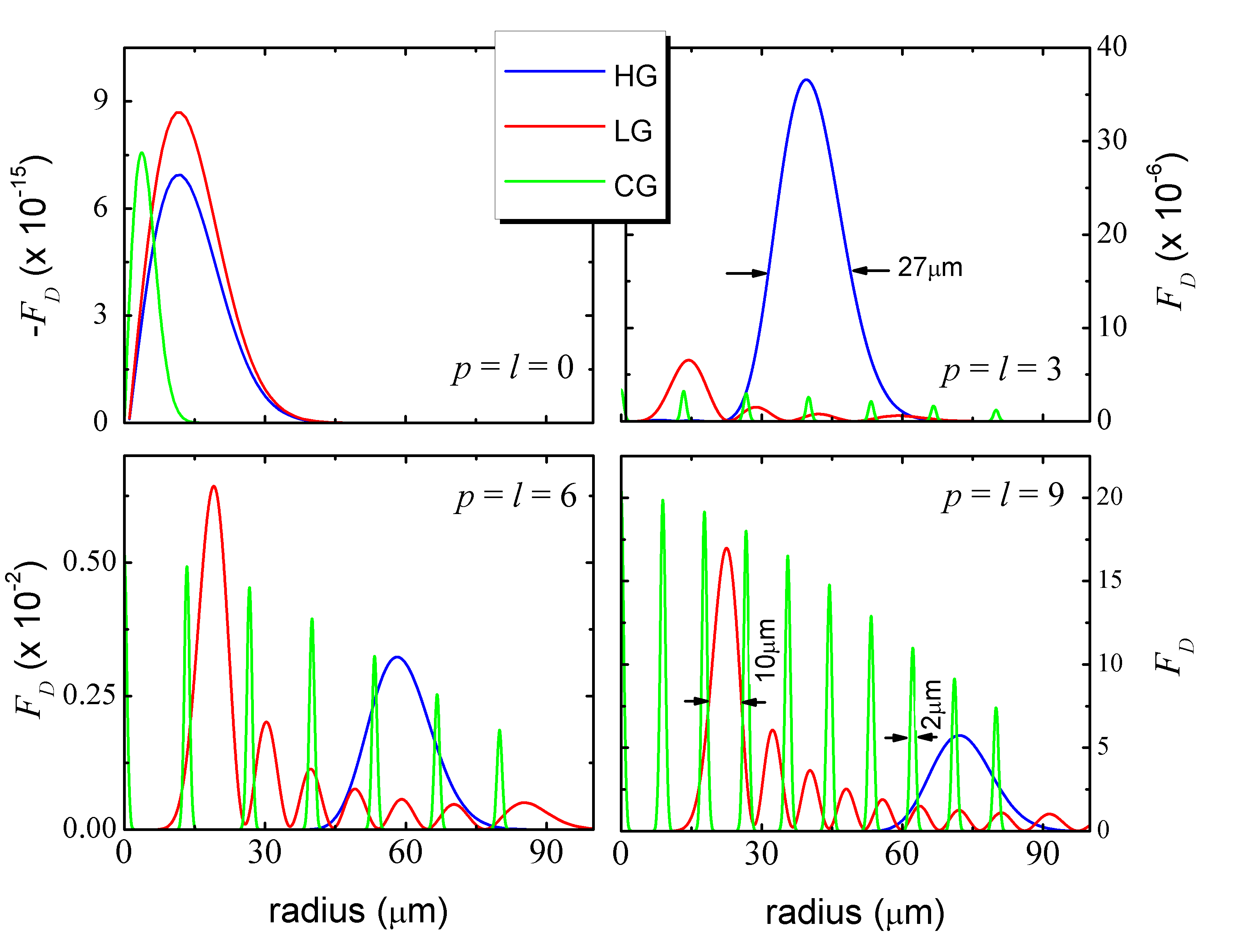
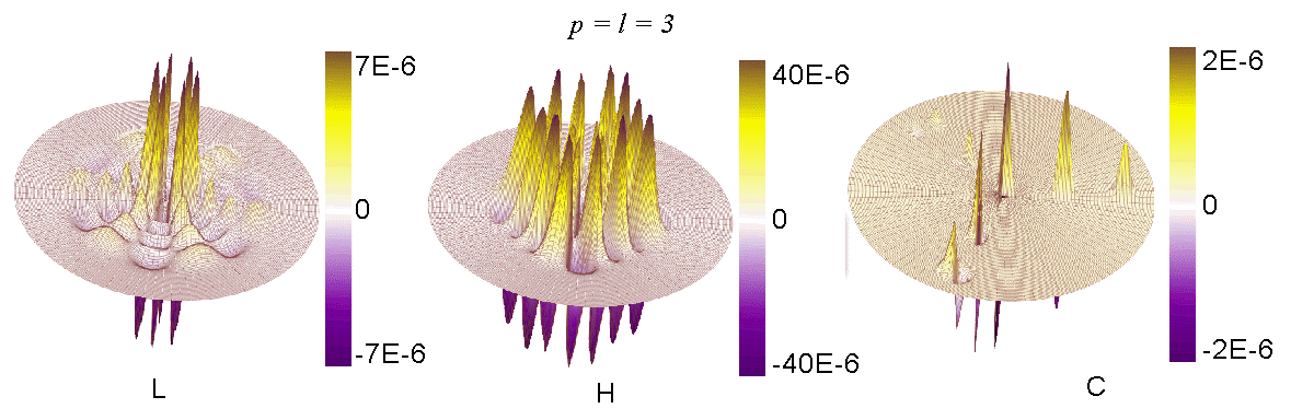
Equations (7) - (11) are utilised in Fig. 2, to demonstrate the ratio of forces () acting on a transparent nanoparticle with a TEM00 mode of laser beam corresponding to . On similar conditions of material parameters the total force acting on the particle for and are exhibited in Figures 3, 4 and 5, respectively. The magnitude of forces in these curves may be attributed to the nature of laser beam profile as given in Figure 1. In these figures, we find that with increasing mode index from to , the ratio can be made to exceed the threshold condition required (i.e. ) to trap a nanoparticle in all three profiles. The nanoparticle will be trapped within the boundary of the lobes obtained for various modes.
In order to obtain the area within which the particle can be trapped,we have plotted as a function of radial distance from beam axis. From Figure 6, we could find that the nanoparticle can be trapped within circle of radius approximately 13.4 m, 5.1 m and 1.1 m, respectively for HG, LG and CG beam profiles. The custom designed profile therefore offers better trapping possibility for a nanoparticle. If particle density within the colloid matrix is such that only few nanoparticles are available within that trap region, then a probability for achieving single nanoparticle trap becomes possible using a custom designed laser profile. If need arises, one can construct a custom designed laser profile with appropriate numbers of modes of minimum possible width to trap a particle. This could be done with suitable program code and addressing it to a high resolution spatial light modulator based on LCD or LCoS device hama .
IV Conclusions
To conclude, we proposed a method to trap submicron to nanometer sized particles in a single beam optical tweezers. The domination of external forces including thermal force which could weaken the chance of trapping nanoparticles are addressed properly. The proposed method suggests the usage of a properly addressed spatial light modulator combined with a nano-positioning piezo device to trap a nanoparticle inside an optical trap. The theoretical estimations for a single semiconductor quantum dots in a buffer solution confirms the possibility of trapping a nanoparticle in a single laser optical trap.
Acknowledgements.
The authors acknowledge the financial support received from UGC and DST, New Delhi. KC thank BIT, Mesra, Ranchi for leave.References
- (1) A. Ashkin, J. M. Dziedzic, J. E. Bjorkholm and S. Chu, Opt. Lett., 288-291, 11 (1986); S. B. Smith, Y. Cui and C. Bustamante, Science, 795-799, 271 (1996).
- (2) N. S. Babcock, R. Stock, M. G. Raizen and B. C. Sanders, Can. J. Phys., 1-9, 99 (2008).
- (3) M. Gerlach, Yu. P. Rakovich, J. F. Donegan, N. Gaponik, A. L. Rogach, Phys. Status Solidi C, 3, 3689-3692 (2006); ibid, Optics Express, 15, 3597-3606 (2007).
- (4) K. J. Van Vliet, G. Bao and S. Suresh Acta Materialia, 51 5881-5905 (2003). http://www.lastek.com.au Model - Nano-HS series., http://www.pi.ws, http://www.physikinstrumente.com Model - D-100.
- (5) E. R. Dufresne and D. G. Grier, Rev. Sci. Instr., 69, 1974-1977 (1998); D. G. Grier and Y. Roichman, Appl. Opt., 45, 880-887 (2006).
- (6) E. R. Dufresne, G. C. Spalding, M. T. Dearing, S. A. Sheets and D. G. Grier, Compuet Generated holographic tweezers.
- (7) C. Basdogan, A. Kiraz, I. Bukusoglu, A. Varol, and S. Dog̃anay, Optics Express, 15, 11616-11621 (2007).
- (8) C.-L. Zhao, L.-G. Wang, X.-H. Lu, Phys. Lett. A, 363, 502-506 (2007).
- (9) J. P. Hoogenboom, D. L. J. Vossen, C. F-Moskalenko, M. Dogterom and A. van Blaaderen, Appl. Phys. Lett., 80, 4828-4830 (2002).
- (10) K. Svoboda, S. M. Block, Opt. Lett., 19, 930 (1994).
- (11) T. Sugiura, T. Okada, Y. Inoue, O. Nakamura, S. Kawata, Opt. Lett., 22, 1663 (1997).
- (12) S. J. Parkin, T. A. Nieminen, N. R. Heckenberg and H. R-Dunlop, Phys. Rev. A, 70, 023816 (2004).
- (13) S. K. Schnelle, E. D. van Ooijen, M. J. Davis, N. R. Heckenberg and H. R-Dunlop, versatile two-dimensional potential
- (14) M. P. MacDonald, K. V-Sepulveda, L. Paterson, J. Arlt, W. Sibbett and K. Dholakia
- (15) Y. R. P. Sortais, H. Marion, C. Tuchendler, A. M. Lance, M. Lamarc, P. Fournet, C. Armellin, R. Mercier, G. Messin, A. Browaeys, and P. Grangier, Diffraction limited optics for single atom manipulation; A. S. Zeleninia, R. Quidant and M.N-Vesperinas, Opt. Lett., 32, 1156-1158, (2007).
- (16) A. N. Grigorenko, N. W. Roberts, M. R. Dickinson and Y. Zhang, Nature Photonics, 2, 365 - 370 (2008).
- (17) T. Iida, H. Ishihara, Phys. Rev. Lett., 97, 117402 (2006); ibid, Nanotechnology, 18, 084018 (2007).
- (18) A. Ashkin, J. M. Dziedzic, J. E. Bjorkholm and S. Chu, Opt. Lett., 11, 288-290 (1986).
- (19) D. Selmeczi, S. F. T.-N rrelykkec, E. Sch fferd, P. H. Hagedorne, S. Moslera, K. B.-S rensenf, N. B. Larsena, H. Flyvbjerg, Acta Physica Polonica B, 38, 2407-2431 (2007); U. F. Keyser, D. Krapf, B. N. Koeleman, R. M. M. Smeets, N. H. Dekker, and C. Dekker, Nano Letters, 5, 2253-2256 (2005).
- (20) Steen H. Mao, J. R. A.-Gonzalez, S. B. Smith, I. Tinoco Jr., and C. Bustamante, Biophysical Journal, 89, 1308-1316 (2005).
- (21) Y. Harada and T. Asakura, Opt. Commun., 124, 529-541 (1996).
- (22) http://www.hamamatsu.co.jp,http://www.holoeye.de