Formation Mechanism of Atmospheric Pressure Plasma Jet
Abstract
Atmospheric pressure plasma jet can protrude some 5.0 cm into air. It holds promise for multivarious innovative applications, but its formation mechanism remains unsettled. We show that the plasma jet is essentially a streamer corona totally independent of, but obscured by, dielectric barrier discharge. Consequently, the jets can be equally successfully generated even with one single bare metal electrode attached to the tube orifice, both downstream and upstream simultaneously, and at a significantly reduced voltage. These results will help understand the underlying physics and facilitate a safer and more flexible implementation of this marvelous plasma source.
pacs:
52.50.Dg, 52.80.Hc, 52.90.+zThe advantages of atmospheric pressure plasma over low pressure discharges are well known. It can be dispensable with the expensive vacuum operation and maintenance, thus it allows many innovative designs to meet the growing demand for cost-effective, reliable and easy-to-operate plasma sources re1 ; re2 . The atmospheric pressure plasma jet (APPJ) is a newly invented, much valuable non-thermal discharge that can protrude into the ambient air for some 5.0 cm, and the ionic temperature is usually below C so that thermally sensitive materials can be treated. These features imply a greatly enhanced applicability of APPJ in materials processing, biomedicine, fabrication industries and so forth re2 ; re3 ; re4 . Various APPJ devices, including jet needle re5 and plasma pencil re6 ; re7 ; re8 , have been designed since 2005. At the same time, the plasma jets are also found to exhibit many intriguing characteristics.
APPJ is an electrically driven phenomenon that merits in-depth research in its own right. Recently, under a high-resolution intensified charge coupled device the jet was found to fire smaller plasma bullets at velocities in the order of re7 ; re8 ; re9 ; re10 ; re11 ; re12 . This triggers a new wave of research enthusiasm towards APPJ re5 ; re10 ; re11 ; re12 ; re13 ; re14 . Lu and Laroussi proposed a model based on photoionization to explain the propagation kinetics of the plasma bullets re7 , while Sands et al. recently noticed that the plasma jet may be initiated independent of the dielectric barrier discharge (DBD) and speculated that it is streamer-like re12 . Yet the plasma jets are usually generated by using the double electrode configuration for DBD, and the mechanism for jet formation remains unsettled. In this letter we show that to generate a plasma jet, the dielectric layer coating the electrodes and the relevant DBD processes are totally irrelevant. Rather, APPJ originates in a streamer corona. In recognition of this fact, we succeeded in obtaining plasma jets with single dielectric electrode or even single bare metal electrode attached to the tube orifice, simultaneously in both downstream and upstream directions, and, more importantly, at a significantly reduced voltage.
Plasma jets concerned here were generated in a quartz capillary with an inner diameter of 2.0 mm and an outer diameter of 3.5 mm. High-purity helium (5N) is used as the working gas. A sinusoidal voltage at 17 kHz is applied for the excitation and sustaining of the discharge. Three distinct electrode configurations are applied to reveal the true origin of the plasma jets: double dielectric electrodes (aluminum foil wrapping the capillary), single dielectric electrode and single bare metal electrode sitting at the tube orifice. Detailed geometry of the electrodes will be specified at proper places. A digital camera (Canon EOS 30D, with a 50 mm lens) and two photo-electron multiplier tubes (PMT, Hamamatsu CR131) are used to study the optical emission from the jets. The output of the PMTs is recorded by an oscilloscope (Tektronix PDO 4032). The line along the two slits of PTM is perpendicular to the quartz tube, and the “vision” of the PMTs spans only about 1.5 mm wide at the axis of the effluent. As having been established by previous studies that the plasma jet comprises a train of high-speed “bullets”, therefore when the plasma bullets pass the front of the PMTs, the registered output will disclose the form and propagation kinetics of the bullets, thus allowing the analysis of the origin for the plasma jet and the calculation of its velocity.
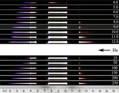
It begins with the observation of “discharge overfall” accompanying the ignition of plasma jets with the DBD configuration (Fig. 1). Note in the upper figure that when the voltage is below 4.0 kV (peak-to-peak value throughout this letter), the discharge cannot fill the gap between the electrodes, and the glow in the jet form appears symmetrically on both flanks of the active electrode. In this case no discharge current can be measured in the circuit connecting the two electrodes. This strongly indicates that the discharge originates at the active electrode. With increasing voltage, the jet grows in length and the glow begins to fill the gap. Remarkably, for voltages between kV, the jet length in air suffers only a negligible change. It is also noticeable that from 8.0 kV on, a glow in pink envelope appears in the overfall zone beyond the ground electrode, and grows with increasing voltage.
Now let’s fix the voltage at 8.0 kV and vary the gas flow. Under given conditions, the overfall always makes its presence and becomes elongated with the increasing gas flow. The discharge overfall is also a plasma jet; in fact, Lu and Laroussi used this effect to generate downstream plasma jet, whereby the ground electrode sits near the tube orifice, and the plasma plume also displays distinct bullets re7 . The discharge overfall is obviously related to the DBD processes, its occurrence here or its escaping others’ notice can be explained as follows. With a very large applied voltage, the polarization charges at the ground electrode will get saturated, and they are insufficient to compensate the discharge process. Therefore the charge accumulation region will expand beyond the ground electrode, leading to an overfall of charges. This is the reason why a glow in the overfall region can be observable only when the voltage exceeds 8.0 kV. The glow induced by charge overfall becomes evidently elongated at larger voltages. As the amount of polarization charges induced at electrode is proportional to the electrode area, consequently a large-area ground electrode is unfavorable for the formation of overfall. We noted that for a ground electrode 5.0 cm wide, the threshold voltage needs be 20 kV. This explains why discharge overfall was not observed in previous studies, e.g., in Ref. re9 where the ground electrode is 5.0 cm wide, whereas the voltage applied is below 15 kV.
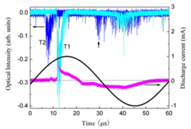
Measurement of the discharge current and optical emission in between the electrodes tells more about the nature of the discharge process. From Fig. 2 we see that the optical signal was first measured near the active electrode which is currently positive in the first half period of the applied voltage, and the discharge current peak lagged by 5.0 s, roughly in step with the large optical signal measured at the ground electrode. This convinces us that the plasma jet propagates from the transient anode to the cathode. The finely resolved optical signal comprises sharp pricks whereas the discharge current varies in a quite smooth manner. In the negative half period, the optical signals measured near both electrodes are synchronous; they are now much reduced in intensity and assume a dispersed distribution in time, indicating a plasma column across the gap between electrodes. Remarkably, in the first half period one more spark of minor intensity was measured at the active electrode. In contrast, identical optical emissions were measured on the two flanks of the active electrode.
The results presented in Figs. 1-2 concluded that the discharge starts from the active electrode, and the discharge current keeps strict pace with only the optical emission near the ground electrode. The plasma jet thrusting into the air and that in between the electrodes are essentially the same, whereas the overfall beyond the ground electrode, whether upstream as here or downstream as in Ref. re7 , is of a different origin. These observations lead to the speculation that the plasma jet originates in a streamer corona instead of being a DBD in spite of the double electrode configuration adopted, since by definition only a corona discharge can be launched by one single electrode re15 . The plasma jet is in fact corona streamer ignited by the strong field at the neighborhood of active electrode, totally independent of DBD process. For DBD, the discharge forms a circuit with the two electrodes, whereas for the jet, the circuit is formed via the diffusion of the carriers in the gas to the virtual ground far away. In the DBD setups previously studied, the DBD and the jet form their own independent circuits. The nature of the latter is simply screened and obscured. If streamer corona is the true responsible mechanism, then APPJ must be equally launched by using single electrode and further getting rid of the dielectric layer. In the following we will demonstrate that by removing the ground electrode, both downstream and upstream plasma jets can be launched simultaneously under proper conditions. Moreover, a simple bare metal electrode can do the job more efficiently.
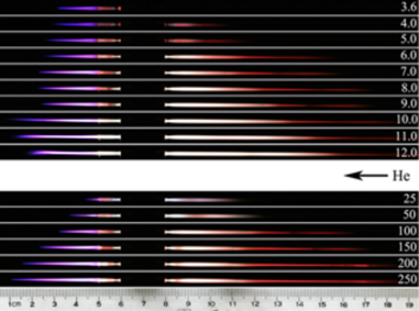
With single dielectric electrode, plasma jets were simultaneously generated in both downstream and upstream directions under similar conditions (Fig. 3). Naturally, now the DBD gap and the overfall region are no more available. The downstream jet extends to a maximum 5.0 cm into the air, whereas the upstream jet measures up to 12 cm. Roughly speaking, the upstream jet assumes a much larger length but demands a higher threshold voltage. The variation of jet length with the applied voltage or the gas flow rate, and the differing behavior for the upstream and downstream jets, substantiate the expectation that the jet length hangs on the active region of the corona re15 . Since inside the tube the disturbing air/helium interface is absent, the relationship between the jet length and the applied voltage is well expressed.
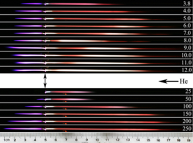
Since it is the streamer mechanism that is responsible for the formation of APPJ, the dielectric barrier to the electrode then bears no relevance. This is to say that a bare metal electrode suffices for jet launching. Figure 4 depicts the APPJs generated with a metal electrode directly attached to the tube orifice. As expected, both downstream and upstream jets were successfully generated (Fig. 4), yet it show some dedicate differences from the jets obtained with the previous two electrode configurations. First, just with a voltage of 4 kV, the jet in the ambient air approaches its maximum length limited by the air/helium interface. This value is 9.0 kV for the double electrode and 7.0 kV for the single dielectric electrode cases. The reason is that the direct contact between the electrode and the discharge avoids the possible energy dissipation by the dielectric layer. Second, at a fixed flow rate of 150 liter/hour, the length of the upstream jet seems unperturbed for voltages over 5.0 kV, whereas in Fig. 3 the jet length steadily grows with the voltage in the given range.
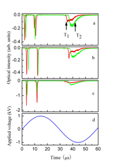
It would be of fundamental interest to compare the kinetic characters of the plasma jets launched with the three different electrode configurations. The temporal evolution of optical emission from the corresponding plasma jets was illustrated in Fig. 5, which was measured at 5 mm and 15 mm away from the orifice, respectively. We see that the three curves display quite the same features. In the positive half-period, two distinct pulses appeared. The presence of the second pulse is a complicated story; it will be discussed elsewhere. A steady time delay is established for the first peak, by which the jet velocity can be determined. For the jets generated under the conditions given in Fig. 5, the propagation velocity measures , and , respectively. These values are in agreement with Refs. re9 ; re10 , whereas the larger value in Refs. re7 ; re12 in the order of is due to the application of a square-wave excitation (typical rise time at 20 ns) and a large overvoltage. From the optical emission measurement and the true-color photographs of the jets, we concluded that roughly the same plasma jets are obtained with the three distinct electrode configurations.
As confirmed above that the plasma jet is in fact a streamer corona obscured by a capillary DBD, and as also revealed by the direct observation of plasma bullets that the temporal development and the structure of plasma jet source is similar to that of a self-sustained streamer discharge in free space re12 , the explanation of the jet velocity should be sought in a model of streamer propagation. Dawson and Winn conceived the first model for the cathode-directed streamer in 1965, and they obtained a streamer propagation rate of , but the head radius of the streamer there is only re15 ; re16 . Based on similar considerations, Lu proposed a modified version to obtain a jet velocity as high as , but the radius of the streamer head is required to be typically for the streamer to be able to self-propagate under low or zero external field re7 . In our case, the velocity is as low as due to the low and slow-varying voltage. Clearly the non-uniformity of the electric field at the electrode plays a pivotal role in determining the launching velocity of the jet. If the jet velocity is taken as the averaged velocity of electron avalanches flying over a distance of the plasma sheath to joint the ionic front, as given by U/ , where U is the potential of the streamer head, is electron mobility in helium, and measures the typical distance of the origin of photoionized electrons to the center of the spherical ionic front, then assuming , this gives a velocity of about at kV. (roughly corresponding to an applied voltage of 4.0 kV). This makes a reasonable estimation to the measured jet velocities. Of course, a more convincing model should include an exact knowledge of the producing of avalanche on the photon path and of the avalanche inception, thus to incorporate the indirect dependence on the shape and the value of applied voltages.
In summary, APPJs generated in previous studies with double electrodes for DBD are essentially a corona streamer. Consequently it would be more appropriately termed a corona plasma jet. Plasma jets of comparable characteristics can be effectively generated with all the three distinct electrode configurations, and in both downstream and upstream directions simultaneously. Particularly, the single bare metal electrode permits a very flexible application of APPJ at reduced voltages. In recognition of the streamer mechanism, a more reasonable qualitative understanding of the plasma jet features has been obtained at the moment; and it warrants a more fruitful exploration of the underlying physics for APPJ which may exhibit more interesting properties. Other alternative methods for the generation of plasma jets are to be expected.
This work was supported by NSFC grant no.10675163, and the National Basic Research Program of China grant no.2009CB930800.
References
- (1) J. Park, I. Henins, H.W. Herrmann, G.S. Selwyn, J.Y. Jeong, R.F. Hicks, D. Shim, and C.S. Chang, Appl. Phy. Lett.76, 288 (2000).
- (2) A. Sch tze, J. Y. Jeong, S. E. Babayan, J. Y. Park, G. S. Selwyn, and R. F. Hicks, IEEE Transactions on Plasma Science 26, 1685(1998).
- (3) M. Laroussi, T. Akan, Plasma Processes and Polymers 4, 777(2007).
- (4) J. Kedzierski, J. Engemann, M. Teschke, and D. Korzec, Solid State Phenomena 107, 119 (2005).
- (5) D. Dudek, N. Bibinov, J. Engemann1, and P. Awakowicz, J. Phys. D: Appl. Phys. 40, 7367 (2007).
- (6) M. Laroussi and X. P. Lu, Appl. Phys. Lett. 87, 113902 (2005).
- (7) X. P. Lu and M. Laroussia, J. Appl. Phys. 100, 063302 (2006).
- (8) X. P. Lu, Z. H. Jiang, Q. Xiong, Z. Y. Tang, and Y. Pan, Appl. Phys. Lett. 92, 151504 (2008).
- (9) M. Teschke, J. Kedzierski, E. G. Finantu-Dinu, D. Korzec, and J. Engemann, IEEE Transaction on Plasma Science 33, 310(2005).
- (10) J. J. Shi, F. C. Zhong, J. Zhang, D. W. Liu and M. G. Kong, Physics of Plasmas 15, 013504 (2008).
- (11) B. L. Sands, B. N. Ganguly, and K. Tachibana, IEEE Transactions on Plasma Science 36, 956(2008).
- (12) B. L. Sands, B. N. Ganguly, and K. Tachibana, Appl. Phys. Lett. 92, 151503(2008).
- (13) R. B. Ye and W. Zheng, J. Phys. D: Appl. Phys. 41, 125202 (2008).
- (14) R. B. Ye and W. Zheng, Appl. Phys. Lett. 93, 071502(2008).
- (15) R. P. Yuri, Gas Discharge Physics, Springer-Verlag, New York (1991), p354.
- (16) G. A. Dawson and W. P. Winn, Z. Phys. 183, 159 (1965).