e-mail: gkozlov@photonics.phys.spbu.ru
Slow Light in a Bragg Waveguide
Abstract
One-dimensional defect photonic crystal (Bragg waveguide) is studied from the viewpoint of the slow light problem. The calculations are presented showing that in the TiO2/SiO2-based Bragg waveguide one can obtain the group index of 1000 and spatial decay length of 3 mm for a nanosecond-scale pulse. Distortion of the pulse due to the group index dispersion proves to be acceptable for the relative pulse delay not exceeding 10. We also analyze propagation of the light pulse in the Bragg waveguide with a quantum well inside and provide arguments showing possibility of reaching the group index of 10000. To the best of our knowledge, analysis of pulse propagation in a Bragg waveguide in connection with the slow light problem has not been performed so far. We will still much appreciate any information about such studies, if any.
I Introduction and basic results
In the last decade, a new direction of optics - so-called ”slow light” - has been developed. The goal of research performed in the framework of this trend is to reduce the light group velocity as much as possible. Importance of these studies is related to practical need of creating compact delay lines for optical systems of information processing. At present, a great number of papers are published devoted to slow light (see, e.g., review Slepov ). In the most famous of them Hau , the light propagation with a group velocity of 17 m/s has been reported. However, the light speed reduction, in this experiment, was observed in a rather narrow spectral range in a medium of supercooled atomic gas. For the system of information processing, such a huge reduction of the light pulse group velocity is not required, while the operating bandwidth (inverse pulsewidth) should be preferentially much broader, e.g., to lie in the range of 109 Hz. It is also desirable not to deal with such exodic media as atomic gas cooled below the point of Bose-Einsten condensation Hau . In the light of these remarks, it seems promising to study slow light in photonic crystals and photonic-crystal-based waveguides Krauss ; Toshihiko . The law of dispersion of electromagnetic waves (here, and are, respectively, the wavenumber and frequency of the wave) in these systems is characterized by the presence of frequencies where tends to infinity and the group velocity of light tends to zero. In photonic crystals, these frequencies correspond to edges of the allowed electromagnetic zones. Similar features of the dispersion law are displayed by the waveguides formed by an extended defect in a photonic crystal, along which an electromagnetic wave localized around this defect may propagate Notomi . The papers devoted to this version of slow light consider, as a rule, propagation of a wave along a linear defect in a planar photonic crystal. Such a defect photonic crystal represents a dielectric plate with regularly arranged apertures (usually in the form of a hexagonal lattice), with the linear defect being a break of this regularity along some line (e.g., a skip of one line of the apertures in the lattice). Mathematical analysis of the electromagnetic wave localized around such a defect is hampered because even the problem of finding forbidden electromagnetic zones in a defectless planar photonic crystal, needed tor this analysis, proves to be rather complicated.
The simplest problem of this type, which still may be important for applications, is the one about propagation of electromagnetic wave along a defect in a one-dimensional photonic crystal. Such a system comprises two closely spaced Bragg mirrors forming the well-known Bragg resonator (or Bragg waveguide). In spite of simplicity of such a system, the slow-light propagation in such a system, to the best of our knowkedge, has not been so far analyzed. This analysis is the objective of the present paper. For the mentioned simplest system, the problem of propagation of an electromagnetic pulse in a gap between two parallel Bragg mirrors can be solved exactly. A complete analysis also proves to be possible for the waveguide comprised of finite Bragg mirrors. In this case, propagation of light is accompanied by attenuation (leakage), which can be also consistently calculated. The main result of this paper is calculation of the Bragg waveguide dispersion law with account for the leakage and demonstration of possibility to delay, in such a waveguide, the light pulse with a duration of 10-9 s by the time substantially exceeding its duration (by a factor of 10 - 30). In this case, the value of the group refractive index appears to be 1000 or higher. The calculations show that fabrication of the Bragg waveguide with acceptable attenuation (leakage) is practically feasible. In particular, to obtain the decay length of 2 - 3 mm in the SiO2/TiO2-based Bragg waveguide, it suffices to apply 15-period Bragg mirrors. To obtain the same attenuation in the GaAs/AlGaAs-based Bragg waveguide, the number of periods should be close to 100. To considerably slow down the light pulse in such systems, the pulse carrier frequency should be chosen to be close to that of the waveguide cutoff . At this frequency the dispersion law of the waveguide shows a singularity where . As a further development of the slow-light technique described above, we analyze the Bragg waveguide with a single quantum well grown inside it. Now, if the resonance frequency of the quantum well lies below the cutoff frequency of the ”empty” waveguide, then the transmission spectrum of such a composite system shows a window in the frequency region close to . The dispersion law within this window appears to be fairly steep which promises further group velocity reduction.
II Bragg waveguide
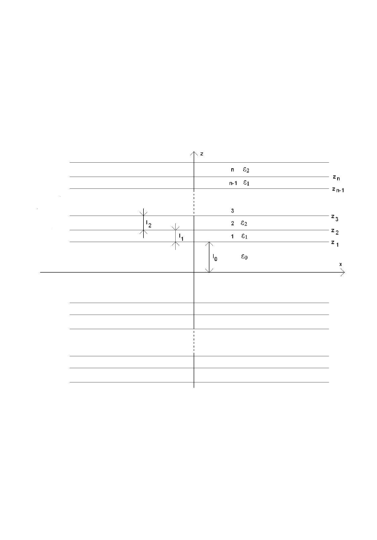
In this section, we calculate propagation of electromagnetic wave with the frequency and wavenumber in the Bragg waveguide with the structure shown in Fig. 1. The waveguide consists of two identical Bragg mirrors arranged symmetrically with respect to the x-y plane at a distance of from this plane. We analyze the case of the TE-wave, with only y-component of the electric field being nonzero. Let us number the layers of the structure in the half-space as shown in Fig. 1. Let be z-coordinate of the boundary between the -th and -th layers of the structure, is the thickness of the -th layer, and is its permittivity. In accordance with the problem formulated above, we have to find solution of the Maxwell equations for the layer structure of Fig. 1 with the dependence on time and -coordinate as . In what follows, for brevity, we do not specify this dependence explicitly, incorporating it into the field amplitudes The Bragg waveguide under consideration has much in common with that comprised of two metal mirrors, whose transmission spectrum, as is known, is bound from below by the cutoff frequency. As we will see below, this property is also characteristic of the Bragg waveguide under study. When the frequency of the electromagnetic oscillations in the waveguide exceeds the cutoff frequency , the wavenumber appears to be a definite real function of the frequency . This function is commonly referred to as the dispersion law. At the same time, the motion of electromagnetic field in the waveguide can be specified in terms of the types of the field oscillations (modes). For this reason, one waveguide may exhibit many dispersion laws , where – is the mode number.
Let us represent the field in the -th layer of the structure (Fig. 1) in the form of a superposition of two waves with the same -components and opposite z-components of the wave vector. Since the field in this layed should satisfy the Maxwell equations, we have . Then the electric field in the -th layer will be given by:
| (1) |
Assume that no light is incident on the Bragg mirror from the upper half-space. Then, there is only outcoming wave in the region i.e., . The amplitude of the wave incident from below onto the upper Bragg mirror and the amplitude of the wave reflected from it are proportional to each other:
| (2) |
with the proportionality factor having the sense of the Bragg mirror reflectivity. Note that -coordinate of the edge of the Bragg mirror is (rather than zero), and the reflectivity should contain the appropriate phase factor. Let us turn now to the field distribution at . We will number the layers in this region of the structure in a symmetric way, and will supply the field amplitudes of the lower Bragg structure with hats:
| (3) |
Since the lower Bragg structure is just the upper one reflected in the plane, we should have:
| (4) |
If the Bragg waveguide (Fig.1) contains a quantum well in the plane , then the field amplitudes are connected by the proper boundary conditions. If the waveguide is empty, then and , hence:
| (5) |
This equation yields in the implicit way the dispersion law of the Bragg waveguide. Let us dwell upon some qualitative features of this law. Consider an ideal Bragg waveguide with infinite number of periods in the mirrors. Then, in conformity with known properties of the Bragg reflector, one can indicate the frequency intervals (forbidden bands of the one-dimensional photonic crystal) within which the reflectivity module equals unity, i.e., the windows of total reflection. Therefore, for the frequencies matching the total reflection windows, we have:
| (6) |
With being a real function. Then, Eq. (5) yields:
| (7) |
Real solutions of this equation provide the laws of wave dispersion, with the integer parameter corresponding to the field oscillation mode number. For the ideal Bragg waveguide, such solutions are possible only at the frequencies exceeding the cutoff frequency , in complete similarity with the waveguide comprised of two metal mirrors. To get some idea about the form of the dispersion law of the Bragg waveguide, we assume that spectral positions of the windows of total reflection and distances between these mirrors are chosen to form a classical Fabry-Perot interferometer. This will be the case when, e.g., the distance between the Bragg mirrors is equal to half the wavelength corresponding to the central frequency of the reflectivity window. In this case, Eq. (5) has a solution at , i.e.,, where is the resonance frequency of the Fabry-Perot interferometer at normal incidence. Calculation of the reflectivity shows that, in fact, it depends on the quantity . Hence, it follows that the dispersion law (5) can be rewritten in the form:
| (8) |
Where . In conformity with the aforesaid, we have
| (9) |
The dispersion law of the Bragg waveguide at small and frequencies close to can be obtained by expanding (8) in series:
| (10) |
Whence
| (11) |
Using this formula, one can see that the group refractive index defined as
| (12) |
turns into infinity at (at ), which motivates the interest to the waveguide under study from the viewpoint of obtaining of slow light.
Turn now to the case of a real Brag waveguide with , for which even for the frequencies matching the windows of total reflection. In this case, solutions of the dispersion equation (5) become complex even in the spectral regions where they were real for the ideal Bragg waveguide. The presence of imaginary part in the wavenumber corresponds to attenuation of the wave, with the relevant modes being referred to as leaking. In what follows we present a consistent mathematical derivation of the expression for reflectivity of the Bragg mirror with a given number of the periods . Though this derivation is standard Koz , the obtained formulas are aimed at derivation of the complex-valued dispersion laws for waveguides with leakage. For this reason, it seems sensible to present this derivation here.
III Reflectivity of the Bragg mirror
To obtain expression for the reflectivity , one has to calculate field distribution in the Bragg structure (Fig. 1). Using the boundary conditions
| (13) |
The field amplitudes in the -th and -th layers can be be interconnected by a linear transformation, which can be written as a product of three transfer matrices:
| (14) |
where
| (15) |
| (16) |
The transfer matrix connecting the field amplitudes in the -th and -th layer evidently has the form:
| (17) |
Turn now to the problem of Bragg mirror. We assume that the first period of this mirror consists of two layers: the first one, with the thickness and permittivity , located at a distance of from the origin of the coordinate system, and the second one with the thickness and permittivity . The transfer matrix corresponding to one period of such a Bragg mirror (we denote it by ) will have the form (ct. with (16)):
| (18) |
where
| (19) |
| (20) |
and
| (21) |
Let us assume that the mirror comprises periods, and the media above and below the Bragg mirror are characterized by the permittivities and , respectively. Then the transfer matrix connecting the field amplitudes below and above the mirror has the form
| (22) |
The matrix entering (22) is determined by the expression
| (23) |
The sought reflectivity can be found from Eq. (22) where and . From the system of equations thus obtained, the reflectivity can be found as:
| (24) |
It is seen from Eq. (22) to calculate reflectivity of the Bragg mirror consisting of periods, one has to calculate -th power of the matrix . To do this, let us find eigen numbers and eigen vectors of this matrix and define the matrix so that its columns are the above eigen vectors:
| (25) |
Then, if , we have
| (26) |
The calculations show that
| (27) |
| (28) |
| (29) |
Note that matrix (23) can be represented as
| (30) |
Then, the Bragg mirror reflectivity can be found from (22):
| (31) |
Using Eq. (26), this formula can be rewritten as
| (32) |
where
| (33) |
while the elements of the matrices , and entering this equation are determined by Eqs. (28)-(30). Thus the dependence of the reflectivity on the number of periods of the mirror is given explicitly by Eq. (32). The limiting value of this coefficient (at ) exists only when . One can see from (27) that if Re , then and, hence, . Thus the condition of total reflection for the Bragg mirror can be written as
| (34) |
Using Eq. (19), this condition can be rewritten in the form:
| (35) |
It is seen that this condition is satisfied, e.g., when and , i.e., when the mirror consists of quarter-wave layers. In this case, Re and, therefore, . Then, from Eq. (32), we have the following expression for the limiting reflectivity:
| (36) |
The matrix elements entering this equation are given by Eqs. (29) and (30). It can be shown that the module of this expression always equals unity, i.e.,
| (37) |
Thus, when reflecting from the infinite Bragg mirror, the wave experiences only variation of its phase, while its amplitude remains intact. Using Eqs. (7), (36), and (37), we can write the dispersion law for the empty ideal Bragg waveguide in the form similar to (7):
| (38) |
Where is integer and is determined by Eq. (37).
IV Propagation of optical pulse in the Bragg waveguid
In this section, we will analyze the possibility of reduction of group velocity of an optical pulse propagating in the Bragg waveguide described above. We will characterize the optical pulse by the carrier frequency and spectral density . The function is peaked at and has the width . When such a pulse is propagating through the waveguide, the field strength as a function of the coordinate abd time can be presented in the form:
| (39) |
where function provides the dispersion law of the waveguide. In conformity with the above conclusions, to obtain a high group refractive index , the cutoff frequency of the waveguide should be chosen as close as possibly to the pulse carrier frequency . At the same time, the pulse spectrum should not come out of the region of waveguide transmission - otherwise, the pulse will be strongly distorted and attenuated. Therefore, the cutoff frequency , the carrier frequency , and the spectral width of the pulse should meet the following inequality:
| (40) |
Assuming here that , and using Eq. (12), we obtain for the greatest group refractive index the following expression:
| (41) |
When the characteristics and of the optical pulse are known, then parameters of the Bragg waveguide with the cutoff frequency , satisfying condition (40), can be found in a standard way. Let, e.g., we want to creat a TiO2/SiO2-based Bragg waveguide. In this case, the values of the material constants are: (TiO2, the first layer), (SiO2, the second layer) (SiO2, the material of the waveguide itself).
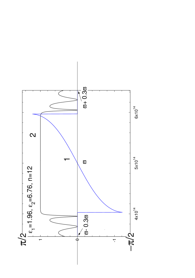
Let us choose corresponding to condition (40). Now we will construct the Bragg mirrors from the following quarter-wave layers . Here . Figure 2 (curve 1) shows frequency dependence of the phase shift plotted using Eq. (37) for this case. The same figure shows the reflectivity spectrum for a finite Bragg mirror at = 12 (curve 2) with the above parameters of the layers. As is seen from Fig. 2, the frequency corresponds to the center of the reflection window, and . Thus, if we choose the half-thickness of the waveguide equal to a quarter of the wavelength (i.e., so that ), the Eq. (38) is satisfied at , and , and, therefore, will be the cutoff frequency of the principal mode of the waveguide described above. In accordance with the results of Sect. 2, the dispersion law of the waveguide in the vicinity of the cutoff frequency will have the form of Eq. (11), where the coefficient can be calculated using Eq. (11) with the derivatives determines from Eq. (36) (these derivatives can be easily computed numerically). After that, the maximum group refractive index can be evaluated using Eq. (41). The calculations performed for the above Bragg waveguide show that can be 1000 and higher for the spectral width of the optical pulse of the order of s-1.
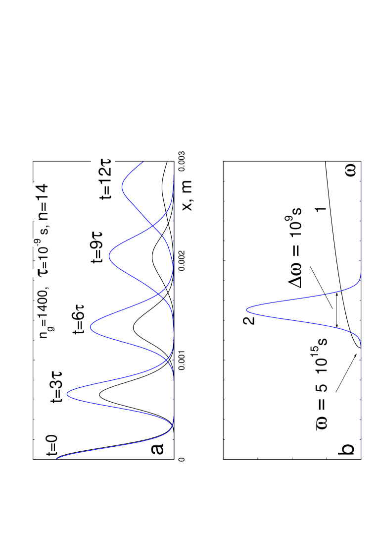
Of great importance is the question about distortion of the pulse in the process of its propagation due to strong group velocity dispersion in the vicinity of the cutoff frequency . This question can be answered by direct calculations of propagation of the pulse with a given spectrum using Eq. (39) with the dispersion law calculated by Eq. (11). The results of these calculations are presented in Fig. 3, which shows propagation of an optical pulse, s long, in the Bragg waveguide described above (fig. 3a) for the case when spectral position of the pulse with respect to the cutoff frequency corresponds to equality in Eq. (40) (fig.3b). In this case, the group refractive index attains its maximum value determined by Eq. (41) and equals . It is seen from Fig. 3a that even in this limiting case (when one could expect a considerable distortion of the pulse upon its propagation) it proves possible to obtain relative delay (the delay expressed in the units of pulsewidth) of about 10 in the waveguide 2 mm in length with the two-fold spatial broadening of the pulse. Similar calculations performed for the case of stronger satisfaction of condition (40) (when the pulse spectrum is shifted from the cutoff frequency by more than its spectral width) show that it is possible to obtain the group refractive index and the relative pulse delay 20 - 30 with acceptable distortion of the pulse shape.
V The effects of leakage in a nonideal Bragg waveguid
Bragg mirrors of real waveguides contain a finite number of periods, and the reflectivity module of such mirrors is always smaller than unity. This gives rise to attenuation of the waves propagating in the real waveguide. From the mathematical point of view, finiteness of the real Bragg mirrors is revealed in the fact that the dispersion law of the real waveguide differs from that for the ideal one by appearance of a complex-valued correction (). The equation that defines the dispersion law will have, as before, the form of (5), but now it will be impossible to reduce it to real-valued equation similar to (7) and (38). Assuming that reflection from the real Bragg mirror is still sufficiently high, we can obtain the complex-valued dispersion law of the real waveguide using the perturbation theory in the following way. The deviation of the reflectivity of the finite Bragg mirror from that of the infinite mirror is assumed to be small. This means that the parameter (see Eq. (32)) is small also. Then, by differentiating (5) in terms of and (in this case, the reflectivity in (5) should be taken in the form of (32)), we obtain:
| (42) |
whence, for the correction connected with the finiteness of the Bragg mirrors, we have the expression:
| (43) |
where is the dispersion law of the ideal Bragg waveguide. The derivatives and increments entering this equation can be easily calculated numerically using Eq. (32). Now, the quantity appears to be complex, which corresponds to appearance of attenuation in the Bragg waveguide. As an example, we have calculated attenuation of an optical pulse in the waveguide described in the previous section for the case of 14-period Bragg mirrors. The results are presented in Fig. 3a, which shows that, in this case, the decrease of the pulse amplitude due to its broadening and due to its leakage prove to be comparable.
VI Bragg waveguide with a quantum well inside
Let now a thin layer with a high value of permittivity be placed in the -plane in the middle of the waveguide. Then the permittivity in the region between the Bragg mirrors will depend on as:
| (44) |
Under such a layer, we will understand a quantum well, which can be grown inside the Bragg waveguide using MBE technique. In this case, the frequency dependence of will show the resonance behavior:
| (45) |
where characterized the strength of interaction of the exciton localized in the quantum well with the electromagnetic field, while is the parameter with the dimension of length, which can be identified, to a certain extent, with the well width. The boundary conditions at , in this case, have the form Koz :
| (46) |
It follows from these conditions that the field amplitudes above ( and ) and below ( and ) the quantum well should obey the relationships (see Sect. 2, Eqs. (2) - (5) and explanations in the text):
| (47) |
where
| (48) |
Presence of the Bragg mirrors leads, as before, to Eqs. (2) and (4). ¿From the condition of nonzero solution of the system of equations (2), (4), and (47) we can obtain the following equation for the wave dispersion in the studied composite structure (waveguide + quantum well):
| (49) |
This equation always has a solution independent of
| (50) |
which shows that the presence of the quantum well does not affect the dispersion laws of odd modes of the empty waveguide, because these modes have a node in the plane of the wuantum well. We are interested in the remaining solutions satisfying the equation:
| (51) |
If we deal with an ideal Bragg waveguide, then the module of the reflectivity equals unity and, hence,
| (52) |
Then, using Eq. (51), we can obtain the following real-valued dispersion relation:
| (53) |
Denoting resonance frequency of the quantum well by , we can rewrite Eq. (53) as
| (54) |
where is an integer. This equation differs from (38) by the third term of the left-hand side, which is related to the presence of the quantum well in the waveguide. This term gives rise to appearance of the isolated dispersion branch in the vicinity of the quantum well resonance frequency. This occurs even when the frequency lies below the cutoff frequency of the empty waveguide. In this case, in the vicinity of the quantum well resonance frequency there arises a transmission window. The upper bound of the window coincides with and its spectral width is proportional to the strength of interaction between the quantum well and the electromagnetic field , with the proportionality factor increasing with approaching the quantum well resonance frequency to the cutoff. The wave dispersion law in this transmission window has the form of (11) with a fairly steep dispersion. The relevant calculations of the group refractive index (under conditions similar to (40)) show that its value may exceed that of the empty waveguide and may reach 10000 for the pulse with a spectral width of s-1.
Note, in conclusion, that the possibility of experimental realization of the above method of the light slowdown in the composite system (waveguide + quantum well) depends on the value of irreversible absorption in the quantum well. Evaluation of this absorption from the measurments of the amplitude and spectral width of the absorption line can be hampered since such measurements often show that the spectral width of the excitonic resonance is, to a considerable extent, of radiative nature.
References
- (1) N.Slepov, Photonics 1/2007 (in Russian), by presentation of R.Boyd et al., Slow Light in Bulk Materials and Optical Fibers. – OFC-2006, OTuA1.
- (2) L.V.Hau, S.E.Harris, Z.Dutton, and C.H.Behroozi, Nature, 397, 594 (1999)
- (3) T.F.Krauss, J. Phys. D: Appl. Phys. 40 (2007) 2666–2670
- (4) Toshihiko Baba, Nature Photonics 2, 465 - 473 (2008)
- (5) M. Notomi, K. Yamada, A. Shinya, J. Takahashi, C. Takahashi, and I. Yokohama, Phys.Rev.Letters v. 87, n. 25, p. 253902-1 (2001).
- (6) G.G.Kozlov, Optics and Spectroscopy, Vol.101, No.1, pp. 151–156 (2006). 161 (2006)