Experimental study of vapor-cell magneto-optical traps for efficient trapping of radioactive atoms
Abstract
We have studied magneto-optical traps (MOTs) for efficient on-line trapping of radioactive atoms. After discussing a model of the trapping process in a vapor cell and its efficiency, we present the results of detailed experimental studies on Rb MOTs. Three spherical cells of different sizes were used. These cells can be easily replaced, while keeping the rest of the apparatus unchanged: atomic sources, vacuum conditions, magnetic field gradients, sizes and power of the laser beams, detection system. By direct comparison, we find that the trapping efficiency only weakly depends on the MOT cell size. It is also found that the trapping efficiency of the MOT with the smallest cell, whose diameter is equal to the diameter of the trapping beams, is about 40% smaller than the efficiency of larger cells. Furthermore, we also demonstrate the importance of two factors: a long coated tube at the entrance of the MOT cell, used instead of a diaphragm; and the passivation with an alkali vapor of the coating on the cell walls, in order to minimize the losses of trappable atoms. These results guided us in the construction of an efficient large-diameter cell, which has been successfully employed for on-line trapping of Fr isotopes at INFN’s national laboratories in Legnaro, Italy.
pacs:
32.80.PjOptical cooling of atoms; trapping and 29.25.RmSources of radioactive nuclei and 32.80.YsWeak interaction effects in atoms1 Introduction
There are several fields of research for which trapped radioactive atoms can be a useful tool. Precise atomic spectroscopy is a test of relativistic quantum-mechanical many-body predictions. Besides their intrinsic interest, these studies are the basis for testing the electroweak model via atomic parity non-conservation (APNC). The electron-nucleon interaction can be probed by measuring the weak charge of the nucleus at low momentum transfers, which is complementary to measurements at high energy; and the measurement of nuclear anapole moments is a unique tool to access weak nucleon-nucleon interactions. The direct study of time-reversal symmetry through the search for permanent electrical dipole moments (EDMs) might also be accessible with trapped atoms. Recent reviews of this field can be found in Refs. Ginges:PR:2004 ; Guena:MPLA:2005 .
Successful trapping of short-lived radioactive atoms was demonstrated at Berkeley Lu:PRL:1994 . In this experiment, atoms were trapped for the purpose of testing the structure of the electroweak interaction by performing precise measurements of decays. Almost simultaneously, atoms were trapped at SUNY Stony Brook Gwinner:PRL:1994 . This group was also the first to trap francium Simsarian:PRL:1996 and to perform extensive spectroscopy on these atoms Gomez:RPP:2006 . The group at JILA Boulder trapped generated by the decay chain of and performed several spectroscopic measurements Lu:PRL:1997 .
Present activities with radioactive atoms in magneto-optical traps include parity violation in decays of Rb and Cs isotopes at LANL Crane:PRL:2001 and Na isotopes by the TRIP team at KVI (Netherlands) Traykov:NIMB:2008 ; the study of anapole moments in francium at TRIUMF (Canada) Gwinner:HI:2006 ; and EDM searches in Ra at ANL (USA) Guest:PRL:2007 and KVI De:arXiv:2008 , and in Fr at RCNP-CYRIC in Japan Sakemi:private:2007 . Our group built the first European facility for the production and trapping of francium at INFN’s national laboratories in Legnaro, Italy Atutov:NPA:2004 ; Stancari:NIMA:2006 ; Stancari:NIMA:2008 ; Stancari:EPJST:2007 . Our long-term goal is to measure parity violation in the atomic transitions of francium.
Francium is the heaviest alkali metal. Its large and highly-charged nucleus enhances APNC and EDM effects. At the same time, its atomic structure is relatively simple, and precise calculations are possible. Francium has several isotopes with lifetimes . They are suitable for trapping and can be compared to estimate nuclear effects.
There are no stable Fr isotopes, but traps can partly compensate for their scarcity. In particular, the magneto-optical trap can cool the atom cloud to temperatures in the millikelvin range and this, due to suppression of the Doppler broadening of atomic lines, greatly increases the intensity of atomic fluorescence and absorption of trapped atoms. This makes these traps suitable for high-resolution, Doppler-free or nonlinear spectroscopy.
The magneto-optical trap also allows one to perform measurements in the pulsed regime. Atoms can be collected on the cell walls or on the surface of the neutralizer. They are then periodically released and accumulated in the trap. The perturbing effects of electromagnetic fields are eliminated by periodically turning off the trap’s magnetic field and laser beams. Measurements can be done during the field-free expansion of the atom cloud. Moreover, in the pulsed regime, the lock-in technique for the detection of small signals can be employed.
Obviously, an efficient optical trapping process is of great importance for the creation of large samples of radioactive atoms. Improvements in the collection efficiency of a MOT is a key consideration for experiments featuring very weak atomic fluxes. The trapping efficiency depends upon several factors, such as laser power, laser beam size, quality of coating, pumping port design, magnetic field gradient, etc.
It is also believed that, in order to obtain maximum efficiency, one should design a cell with a large ratio between the volume occupied by the laser beams and the total cell volume Lu:PRL:1997 ; Stephens:PRL:1994 ; Aubin:RSI:2003 . For instance, for an available trapping laser power of 1 W and for a saturation power of , the cell diameter must be of the order of 5 cm for full overlap of laser beams and cell volume. Some serious problems arise with this kind of cell. First of all, a small cell makes it difficult to insert a hot piece of metal (neutralizer) inside the trapping volume. The neutralizer is necessary when radioactive isotopes are transported as ions. A hot neutralizer inside the trap volume can damage the wall coating and degrade vacuum conditions. A possible solution is to place the neutralizer outside the cell’s pumping port, but this usually reduces the collection efficiency dramatically. Moreover, a small cell suffers from high levels of stray light, which make it difficult to directly detect low levels of fluorescence.
A possible dependence of the trapping efficiency on the MOT cell size for a given laser beam radius is the main object of our experimental study. We trapped Rb atoms in a magneto-optical trap with three different vapor cells. These cells have different volumes but exactly the same pumping port, which consists of a coated glass tube. In all these experiments, the same source of atoms and optical detection system were used. We also present the results of a study on the variation of the density of trappable atoms in the cell as a function of port tube length; and we demonstrate the importance of passivation of the coating on the cell walls with an alkali vapor in order to minimize the loss rate of trappable atoms. These experimental studies are preceded by the discussion of a model of the trapping process and by the definition of the relevant quantities.
2 Loading of a vapor cell
Let us consider a spherical cell with radius and with an entrance or exit port in the shape of a cylindrical tube with internal radius and length . The cell is connected to a vacuum pump through the exit port and a valve. The surfaces of the cell, port, and valve are covered with a non-stick coating. Radioactive ions from a beam trasport line are injected into the cell and impinge on the neutralizer, a hot metal plate placed at the far end of the cell. The trap’s laser beams and magnetic field are turned off.
After the radioactive ion beam is switched on, the ions come inside the cell and impinge on the neutralizer, stick to its surface for a short time, become neutralized and are finally desorbed and released into the cell volume. Atoms can also be injected directly into the cell in neutral form. In both cases, atoms start to fill the cell and to saturate its walls, and the density of the vapor starts to increase. The density of atoms in the cell reaches an equilibrium value when the sum of all loss rates — the leaking or escaping of atoms from the cell through the port tube , their chemical adsorption on the cell walls and their radioactive decay — becomes equal to the flux of atoms into the cell:
| (1) |
In our case, can be calculated from the conductance of the port tube in the molecular-flow regime multiplied by the the density difference :
| (2) |
where is the average atomic thermal velocity at temperature , and is the mass of the atom.
The loss rate is the flux of atoms towards the internal surface of the cell walls. The atoms are absorbed with probability by chemiosorption on the coating. The parameter is also interpreted as the average number of bounces it takes to adsorb atoms on the surface of the coating. The loss rate by chemisorption can be expressed in the following form:
| (3) |
Here we neglect the chemical loss of atoms in the neutralizer.
The loss rate due to radioactive decay is:
| (4) |
where is the total number of atoms in the cell, is the cell volume , and is the radioactive lifetime. In a coated cell with a sufficiently hot neutralizer, the sticking time of atoms to the coating and to the surface of the neutralizer is much shorter than their radioactive lifetime. The radioactive loss of atoms on the cell walls or on the neutralizer can therefore be neglected.
We note that in this model the requirement for the sticking time of atoms to the coating is much less strict than the one discussed in Ref. Stephens:JAP:1994 : for obtaining a high trapping efficiency, it is sufficient that the sticking time be small compared with the radioactive lifetime.
The equilibrium condition (Eq. 1) becomes
| (5) |
and one can write the total number of atoms in the cell at equilibrium as follows:
The first term between square brackets in Eq. 2 is the inverse escape time , which represents the average time it takes to lose atoms through the pumping port:
| (7) |
The second term is the inverse storage time of atoms inside a closed cell before being lost to chemisorption on the cell walls:
| (8) |
In the steady-state regime, the total number of atoms in the cell can be written in the following compact form:
| (9) |
where is the total loss rate of trappable atoms, defined as follows:
| (10) |
and is the total loss time.
In a typical trapping experiment with radioactive atoms in a coated cell, the escape time is much shorter than both the storage time and the radioactive lifetime. Under these conditions, the contribution of the storage and decay times can be neglected, and the total number of atoms at equilibrium becomes
| (11) |
and the density of trappable atoms in the cell is
| (12) |
For instance, in the case of francium, we have and . For and , we expect the steady-state density to be . It is interesting to note that the steady-state density is proportional to the incoming flux , to the length of the cell port tube, and to the inverse cube of the port tube radius ; and it is independent of the cell radius .
Let us consider the case of a coated cell whose inlet is a diaphragm () instead of a port tube. Also in this case, the escape time (Eq. 7) is small compared to the storage time (Eq. 8), and the steady-state density does not depend on cell size. A high density of trappable atoms is an important starting point for obtaining a large trap population. In the case of a diaphragm, one expects the density to be much smaller with respect to the case of a port tube of the same diameter. In the latter, ions are injected into the cell by a fast and free ballistic flight, and atoms leak out by diffusion, which is relatively slow.
In the case of an extremely small entrance port Lu:PRL:1997 or of an uncoated cell, the storage time is smaller than both the escape time and the radioactive lifetime. The loss of atoms is dominated by chemisorption on the cell walls, and the equilibrium density can be expressed as follows:
| (13) |
In this case, the steady-state density is proportional to the product of the incoming flux and number of atom bounces inside the cell, and it is inversely proportional to the internal area of the cell surface. In this particular case, the size of the cell must be kept as small as possible in order to optimize the steady-state density of trappable atoms, the number of trapped atoms and the trapping efficiency (discussed below).
3 Trapping process in a coated cell
Let us consider the trapping process in a magneto-optical trap with a coated cell containing a vapor of trappable atoms. The trapping process can be modeled according to Ref. Lu:PRL:1997 . The time evolution of the number of trapped atoms and the number of trappable atoms in the vapor depends on three parameters: , the loading rate of atoms from the vapor to the trap; , the collisional loss rate of atoms from the trap to the vapor due to collisions with the rest gas; and (mentioned above), the total loss rate of atoms from the vapor. In differential form, this model can be expressed as follows:
| (14) |
Here we neglect the loss of trapped atoms due to their collisions with other atoms in the trap.
At equilibrium, the number of trapped atoms is
| (15) |
and the total number of trappable atoms in the vapor is
| (16) |
Taking Eqs. 15 and 16 into account, one obtains:
| (17) |
According to Ref. Stephens:PRL:1994 , the combination in Eq. 17 is the trap capture rate , where is the radius of the trapping laser beams and a parameter that depends upon the thermal velocity of trappable atoms and the trap capture velocity . The number of trapped atoms can be written in the following form:
| (18) |
Taking Eq. 12 into account, we finally obtain:
| (19) |
One can see from Eqs. 18 and 19 that the steady-state number of trapped atoms is proportional to the density of the trappable atoms in the vapor; and that it is proportional to the flux, to the radius of the laser beams squared, to the length of the pumping tube, and inversely proportional to the collision rate of cold atoms with the rest gas and to the radius of the pumping tube cubed.
One can define a (dimensional) trapping efficiency as the ratio between the number of trapped atoms at equilibrium and the incoming atomic flux:
| (20) |
According to this model, the trapping efficiency does not depend on the cell size, unless this dependence is hidden in the constant .
4 Experimental setup
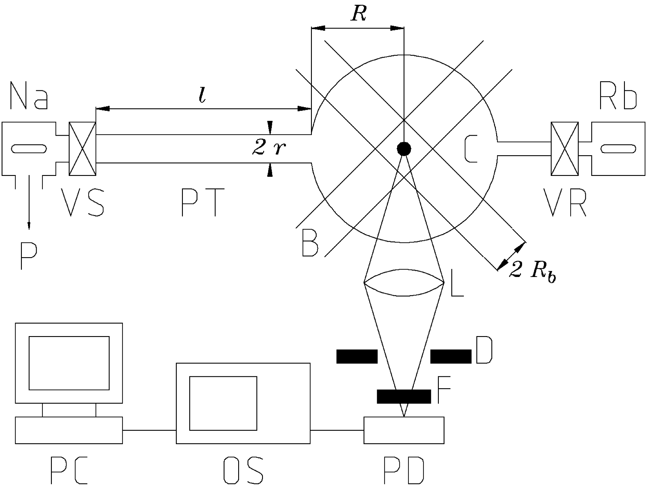
Our MOT consists of a spherical glass cell with a glass port tube (Fig. 1). We have 3 spherical cells with different internal radii : 7.0 cm, 3.0 cm, and 1.5 cm. The cylindrical port tube has internal radius and length ; its dimensions are the same for all 3 cells. These cells can be easily interchanged without affecting the diameter of the laser beams, their alignment, the magnetic field, and the optical detection system. The same vacuum conditions can also be obtained, albeit with different pumping times.
In these experiments we do not use an ionic beam. The neutralizer is therefore removed and the back port of the cell is connected through a small valve to a source of Rb atoms, whose temperature can be reduced to as low as and controlled by a thermocouple. The cell, the port tube and the valves are coated with a PDMS coating by following the standard procedure described in Ref. Atutov:PRA:1999 . We have also used a Dryfilm coating and found similar results, but in this paper only the results with PDMS are presented.
Two coils provide a quadrupole magnetic field with field gradients as large as . The trapping laser is a free-running Ti:sapphire laser, delivering a maximum power of about 600 mW at a wavelength of 780 nm. The laser frequency is scanned across the , to , Rb transition by changing the temperature of the aluminum resonator. This leads to a periodic appearing and disappearing of the cloud of cold trapped atoms. The scanning time is 10 s, which is slow enough for the trap to reach steady state. A passively-stabilized, free-running diode laser with a power of 10 mW is tuned to the , to , transition for repumping. The trapping and repumping beams are superimposed by a polarizing cube and split into 6 beams. Their diameter is expanded by 6 telescopes and controlled with diaphragms to select the central and uniform part of the beam. The maximum beam diameter is 3 cm.
The fluorescence of both the vapor atoms and the trapped atoms is collected by lenses and then imaged by a fast and calibrated photodetector equipped with an iris diaphragm and an interferential filter, both placed near the surface of the photodetector. The signal from atoms in the vapor is usually weaker than the one from trapped atoms. For this reason, the diameter of the iris diaphragm is chosen to be large enough to make the two signals comparable. As a consequence, the image of the cloud of cold atoms is much smaller than the size of the photodetector, and its signal is not sensitive to variations in the position of the trap or in the size of the iris diaphragm. The signal is recorded by a lock-in amplifier and a digital oscilloscope connected to a personal computer. It is verified that the electronic response of the detector varies linearly with the intensity of incident light.
5 Density of atoms in the vapor cells
In this section, we present the results of a study on the vapor density in the 3 different cells when the MOT trapping beams and magnetic field are turned off. A high density or a large total number of trappable atoms in the vapor is an important starting point to achieve high-efficiency magneto-optical trapping of radioactive atoms.
At the beginning of each experiment, we measure the level of stray light generated by each cell. We find that the intensity of stray light strongly depends on cell size, and it is roughly proportional to the inverse cube of the cell radius. The small cell produces an intensity that is about 50 times larger than that of the large cell. A high level of stray light can seriously disturb the detection of small fluorescence signals, both from trapped and vapor atoms.
We find that all freshly-coated cells do not show any fluorescence from Rb atoms when valve VR is opened, meaning that the storage time is very small. This can be attributed to the fact that a fresh coating has a chemically active surface, probably due to chemically-active gases such as oxygen or water adsorbed on its surface. Rubidium atoms can also diffuse inside the coating, where they can be trapped by chemically-active molecules mixed with the molecules of the coating.
To minimize the residual chemical activity of the coating, we carry out a passivation (or curing) procedure Lu:PRL:1997 ; Bouchiat:PR:1966 . First of all, we continuously pump the cell to obtain a residual-gas pressure of . It usually takes about one week to get good vacuum conditions for the largest cell and less time for smaller cells. To start passivation, we heat the source of sodium atoms and open valve VS, so that the pressure of the alkali vapor in the cell is kept at about . We investigate passivation with sodium, potassium and rubidium itself, obtaining very similar results. In the following, only measurements with sodium passivation are discussed.
To measure the steady-state density of trappable atoms , we tune the laser frequencies to be resonant with the trapping and repumping transitions of rubidium, until we obtain maximum fluorescence in a separate reference cell. Five of the laser beams are blocked, leaving only one open. This is done to avoid the influence of optical molasses on the escape time and on the atomic density at equilibrium. Valve VS is then closed. This prevents sodium from entering the cell and rubidium from leaking out. Subsequently, valve VR is opened and atoms from the Rb source, kept at constant temperature, are allowed to fill the cell, until equilibrium is reached. This usually takes about 30 s. Finally, we record the level of fluorescence, which is proportional to the steady-state density of trappable atoms .
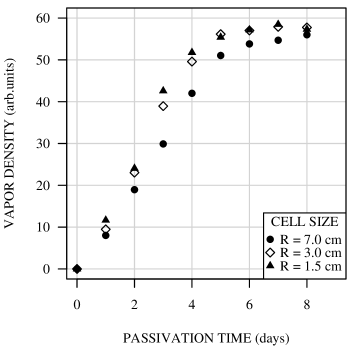
Figure 2 shows how the equilibrium density depends on the duration of the passivation process for each of the 3 cells. At the beginning of the passivation process, the equilibrium density is very small in all 3 cells. After about 7 days of continuous passivation, the equilibrium density approaches a limit, which is practically the same for all 3 cells. This is in agreement with the model (Eq. 12). The smallest cell is passivated in a slightly shorter time. From our measurements we deduce that, for all cells, the increase in the equilibrium density after passivation is approximately a factor .
The storage time and the total loss time are measured in the large cell in parallel with the measurement of the equilibrium density during passivation. For the measurement of the storage time , we close valve VS between the cell and ionic pump, open valve VR between the Rb source and the cell and fill the cell with vapor. Then, we rapidly close the source valve VR and record the decay of the vapor fluorescence in the cell. We extract the storage time from the exponential part of the decay curve, when valve VR is closed. To make sure that Rb atoms are permanently removed from the vapor, we sometimes heat the cell walls and check that the vapor does not reappear. This indicates that atoms are bonded to the surface of the coating by chemisorption rather than physisorbed.
To obtain the loss time we fill the cell with vapor, then we close valve VR and immediately open valve VS, allowing the number of atoms in the vapor to decay by both leaking out of the cell and by adsorption on the cell walls. The transmitted intensity as a function of time is recorded and the loss time is extracted from the decay curve.
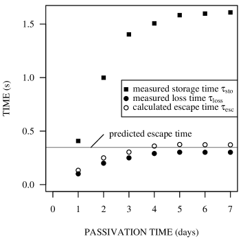
Figure 3 shows and as a function of the passivation time in the large cell. Both the storage and the loss time are initially very small. They increase during passivation and reach their maximum values after about one week. From the final value of the storage time and Eq. 8 with and , one finds that, according to the model, the average number of bounces before adsorption on the cell walls is .
From the measurements of loss time and storage time, it is possible to estimate the escape time using Eq. 10 with infinite :
| (21) |
After one week of passivation, we measure and . From these values, we find . This measurement is in agreement with the prediction given by Eq. 7. In fact, for a cell radius , port-tube dimensions and , and Rb thermal velocity , Eq. 7 yields .
With this technique, it is not possible to measure loss times and escape times in the smaller cells. These times are short, and the valves’ opening and closing times cannot be neglected. This is also the reason why the estimated escape time in the large cell (Fig. 3) is not constant, as one may expect. Nevertheless, useful information on the performance of the large cell can be extracted, as shown above.
6 Trap population and trapping efficiency


We performed experiments to study the population of cold Rb atoms in the magneto-optical trap and to measure the trapping efficiency in 3 MOT cells of different sizes. We detect the fluorescence signal from cold trapped atoms with the same photodetector and optical system that is used for the vapor studies.
In all experiments presented in this section, the Rb source is cooled in order to reduce as much as possible the Rb vapor pressure in the cell. This is done to minimize the loss of cold atoms due to collisions with trappable Rb atoms in the vapor. Below a temperature of about , we observe that the intensity of fluorescence from trapped atoms is proportional to the fluorescence from the vapor. This is an indication that the contribution of collisions (i.e., a possible term in Eq. 14) is negligible.
In the case of low vapor densities, the model predicts that the trap population is proportional to the length of the port tube (Eq. 19). In the large cell, we measure the variation of the trap population as a function of the length of the tube by positioning a movable, nitrogen-cooled metallic ring around the tube itself. The effective length of the tube is shortened by adsorption on the cold surface, which acts as a movable atom sink. With this arrangement, one can smoothly vary the experimental conditions from a long-port-tube case to a diaphragm case.
Figure 4 shows the measured intensity of the trap fluorescence as a function of the position of the cooled metallic ring, i.e. the effective length of the port tube. In accordance with the model, the trap population appears to increase linearly with port-tube length. For the shortest port-tube length of 1 cm, the equilibrium trap population is about 6 times smaller than that obtained, in the same cell, with the maximum port-tube length of 16 cm.
To measure the dependence of the trap population on the pressure of the rest gas in the cell, we switch off the ionic pump attached to the MOT and let the rest-gas pressure become uniform in the vacuum system. Without pumping, the rest-gas pressure, which is monitored by a vacuum gauge positioned near the cell, slowly increases. A measurement of how the trap fluorescence in the large cell diminishes with increasing rest-gas pressure is shown in Fig. 5. The plot shows that the trap population is roughly inversely proportional to the rest-gas pressure, in agreement with the prediction (Eqs. 15 and 19).
Finally, we provide a comparison of the trapping efficiency measured in the 3 cells of different sizes. To eliminate uncertainties due to the Rb flux , we measure the ratio of two light signals: the fluorescence intensity from cold atoms in the trap and the one from trappable atoms in the vapor. Since is proportional to , the ratio is proportional to the trapping efficiency . We measure this ratio for each cell using the same optical system and with the same rest-gas pressure.
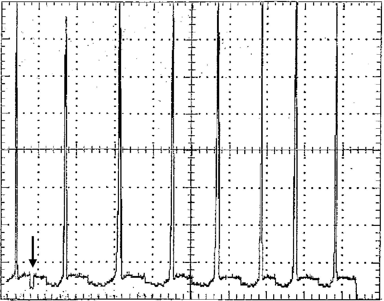
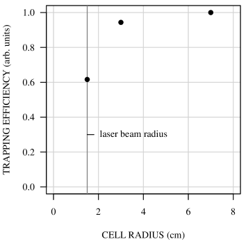
The fluorescence recorded in the large cell as a function of time is presented in Fig. 6. The frequency of the trapping laser is slowly scanned across the trapping transition several times, while the frequency of the repumping laser is kept at the maximum of the repumping line. In this figure, one can see the fluorescence signal from trapped atoms (narrow peaks) and from trappable atoms in the vapor (broad background level). Due to the linear response of the photodetector, the height of the narrow peaks is proportional to the number of trapped atoms. To determine a signal proportional to the density of trappable atoms in the vapor, the frequency of the repumping laser is briefly detuned away from the repumping transition. Due to optical pumping, this detuning produces a gap of zero signal, indicated by an arrow in Fig. 6. The ratio of signal heights referred to this zero level gives a value that is proportional to the trapping efficiency . The value of the trapping efficiency is obtained by averaging about 10 of these signal ratios for each cell. The statistical uncertainty is . The trapping efficiency as a function of cell size is shown in Fig. 7. The two larger cells have comparable efficiency, while the efficiency of the small cell, whose radius coincides with the radius of the laser beams, is 38% smaller than that of the large cell.
The small cell may appear inefficient due to the large curvature of its walls, which can act as a meniscus lens and affect the spatial distribution of laser power. This may produce a lower number of trapped atoms even in the regime of deeply-saturated laser power. We check that this possible systematic effect is negligible by inserting in the laser beams near the cell a thin, milky-white transparent plastic sheet, which produces a more uniform light distribution. We can also use a 6-cm-long, 3-cm-diameter cylindrical cell, which fits inside the laser beams. In both cases, we obtain the same decrease in trapping efficiency with respect to the larger cells.
In principle, the resonant absorption of light in the trap or in the vapor changes with the size of the cell, resulting in seemingly different trapping efficiencies. These systematic effects are negligible with this technique. In fact, the effect of the optical thickness of the trap is eliminated by using similar trap populations in all 3 cells. And even though the optical thickness of the vapor is larger in larger cells, the fluorescence ratios are not affected, because trap and vapor fluorescence are attenuated by approximately the same amount.
These results are in contradiction with the common opinion according to which the maximum trapping efficiency is associated with a maximum ratio of laser beam overlap and cell volume. A possible interpretation is the following. At first, the optical molasses collects a sample of cold atoms over the laser beam volume in a few tens of milliseconds. The cold atoms are then pushed towards the center of the cell by the relatively weak influence of the magnetic field in about one second. The magnetic field does not seem to contribute to the cold atom population. This is suggested by the fact that the total molasses and trap fluorescence signals are approximately equal. Atoms in the molasses can drift towards the trap or be lost due to heating by the cell walls. In the small cell, the probability of an atom in the molasses to come into contact with the cell walls and be heated is larger. This interpretation is supported by the fact that attempts to increase the number of trapped atoms by frequency chirping, broadband light or by light with several closely spaced frequency components (to increase the low-velocity tail in the Boltzmann-Doppler velocity distribution) were not successful Lindquist:PRA:1992 ; Gibble:OL:1992 . Experimental investigations on the role of molasses in a magneto-optical trap will be presented in a separate paper.
7 Conclusions
An experimental study of rubidium magneto-optical traps was presented and compared with a model of vapor collection and trapping. We verified that the density of trappable atoms in the vapor does not depend on the size of the cell, and demonstrated the importance of passivating the coated surfaces of the cell. We showed how the trap population increases with the length of the port tube and with the quality of the vacuum. A larger trapping efficiency was observed for the larger cells.
These results are the basis for the design of efficient traps for radioactive atoms. Using a relatively large cell with a long port tube has several advantages. Besides being easier to handle, it prolongs the lifetime of the coating in the presence of an internal heated neutralizer. A possible disadvantage is the pumping time required to reach acceptable vacuum conditions, especially in the case of organic coatings. For our on-line experiments this is not a problem, because the pumping time (approximately two weeks) is anyway shorter than the interval between days of beam time. Recently, our MOT was successfully used for the on-line trapping of several francium isotopes at LNL, INFN’s national laboratories in Legnaro, Italy deMauro:arXiv:2008 ; Sanguinetti:arXiv:2008 .
8 Acknowledgements
We would like to thank Klaus Jungmann (KVI Groningen) and Carl Wieman (University of British Columbia and University of Colorado, Boulder) for reading the manuscript and for sharing their valuable insights. The authors are also grateful to Paolo Lenisa and Guido Zavattini (Università di Ferrara) for their interest in this work and for useful discussions.
This work was supported by INFN, the Italian institute for nuclear physics; and MIUR, the Italian governmental department of education and research.
References
- (1) J.S.M. Ginges, V.V. Flambaum, Phys. Rep. 397, 63 (2004)
- (2) J. Guena, M. Lintz, M.A. Bouchiat, Mod. Phys. Lett. A 20, 375 (2005)
- (3) Z.T. Lu, C. Bowers, S.J. Freedman, B.K. Fujikawa, J.L. Mortara, S.Q. Shang, K.P. Coulter, L. Young, Phys. Rev. Lett. 72, 3791 (1994)
- (4) G. Gwinner, J.A. Behr, S.B. Cahn, A. Ghosh, L.A. Orozco, G.D. Sprouse, F. Xu, Phys. Rev. Lett. 72, 3795 (1994)
- (5) J.E. Simsarian, A. Ghosh, G. Gwinner, L.A. Orozco, G.D. Sprouse, P.A. Voytas, Phys. Rev. Lett. 76, 3522 (1996)
- (6) E. Gomez, L.A. Orozco, G.D. Sprouse, Rep. Progr. Phys. 69, 79 (2006)
- (7) Z.T. Lu, K.L. Corwin, K.R. Vogel, C.E. Wieman, T.P. Dinneen, J. Maddi, H. Gould, Phys. Rev. Lett. 79, 994 (1997)
- (8) S.G. Crane, S.J. Brice, A. Goldschmidt, R. Guckert, A. Hime, J.J. Kitten, D.J. Vieira, X. Zhao, Phys. Rev. Lett. 86, 2967 (2001)
- (9) E. Traykov, U. Dammalapati, S. De, O.C. Dermois, L. Huisman, K. Jungmann, W. Kruithof, A.J. Mol, C.J.G. Onderwater, A. Rogachevskiy et al., Nucl. Instr. Meth. Phys. Res. B 266, 4532 (2008)
- (10) G. Gwinner, E. Gomez, L. Orozco, Perez, D. Sheng, Y. Zhao, G. Sprouse, J. Behr, K. Jackson, M. Pearson et al., Hyp. Inter. 172, 45 (2006)
- (11) J.R. Guest, N.D. Scielzo, I. Ahmad, K. Bailey, J.P. Greene, R.J. Holt, Z.T. Lu, T.P. O’Connor, D.H. Potterveld, Phys. Rev. Lett. 98 (2007)
- (12) S. De, U. Dammalapati, K. Jungmann, L. Willmann (2008), arXiv:0807.4100
- (13) Prof. Yasuhiro Sakemi, Cyclotron Radioisotope Center, Tohoku University, Japan, private communication (December 2007).
- (14) S. Atutov, V. Biancalana, A. Burchianti, R. Calabrese, L. Corradi, A. Dainelli, V. Guidi, A. Khanbekyan, B. Mai, C. Marinelli, Nucl. Phys. A 746, 421 (2004)
- (15) G. Stancari, S. Veronesi, L. Corradi, S.N. Atutov, R. Calabrese, A. Dainelli, E. Mariotti, L. Moi, S. Sanguinetti, L. Tomassetti, Nucl. Instr. Meth. Phys. Res. A 557, 390 (2006)
- (16) G. Stancari, L. Corradi, A. Dainelli, Nucl. Instr. Meth. Phys. Res. A 594, 321 (2008)
- (17) G. Stancari, S.N. Atutov, R. Calabrese, L. Corradi, A. Dainelli, C. de Mauro, A. Khanbekyan, E. Mariotti, P. Minguzzi, L. Moi et al., Eur. Phys. J. ST 150, 389 (2007)
- (18) M. Stephens, C. Wieman, Phys. Rev. Lett. 72, 3787 (1994)
- (19) S. Aubin, E. Gomez, L.A. Orozco, G.D. Sprouse, Rev. Sci. Instr. 74, 4342 (2003)
- (20) M. Stephens, R. Rhodes, C. Wieman, J. Appl. Phys. 76, 3479 (1994)
- (21) S.N. Atutov, V. Biancalana, P. Bicchi, C. Marinelli, E. Mariotti, M. Meucci, A. Nagel, K.A. Nasyrov, S. Rachini, L. Moi, Phys. Rev. A 60, 4693 (1999)
- (22) M.A. Bouchiat, J. Brossel, Phys. Rev. 147, 41 (1966)
- (23) K. Lindquist, M. Stephens, C. Wieman, Phys. Rev. A 46, 4082 (1992)
- (24) K.E. Gibble, S. Kasapi, S. Chu, Opt. Lett. 17, 526 (1992)
- (25) C. de Mauro, R. Calabrese, L. Corradi, A. Dainelli, A. Khanbekyan, E. Mariotti, P. Minguzzi, L. Moi, S. Sanguinetti, G. Stancari et al. (2008), (to be published in Phys. Rev. A), arXiv:0808.0152
- (26) S. Sanguinetti, R. Calabrese, L. Corradi, A. Dainelli, A. Khanbekyan, E. Mariotti, C. de Mauro, P. Minguzzi, L. Moi, G. Stancari et al. (2008), arXiv:0807.4397