Novel approach to a perfect lens
Abstract
Within the framework of an exact analytical solution of Maxwell equations in a space domain, it is shown that optical scheme based on a slab with negative refractive index () (Veselago lens or Pendry lens) does not possess focusing properties in the usual sense . In fact, the energy in such systems does not go from object to its ”image”, but from object and its ”image” to an intersection point inside a metamaterial layer, or vice versa. A possibility of applying this phenomenon to a creation of entangled states of two atoms is discussed.
pacs:
78.20.Ci, 42.30.Wb, 73.20.Mf, 78.66.BzRecently due to the work of Veselago Veselago , much attention has been paid to a so called perfect lens, whose properties are due to particular features of media with negative refractive index. Keen interest to this theme was aroused by the work of Pendry Pendry , where because of impossibility to produce media with negative refractive index he had proposed to use metallic films with for near field focusing. The attempts to make a perfect lens have already involved interesting experiments on optical near field focusing (superlenses Zhang1 , hyperlenses Zhang2 ; Smolyaninov , and nanolenses Kawata ). However, the Veselago perfect lenses Veselago with have not yet been achieved, and as will be shown below, they cannot be realized due to the reasons not at all connected with technical difficulties of making a metamaterial with negative refractive index. The fact is that a conventional picture of operation of a perfect lens is incorrect, because it disagrees with the standard Maxwell equations.
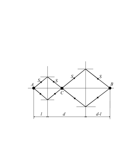
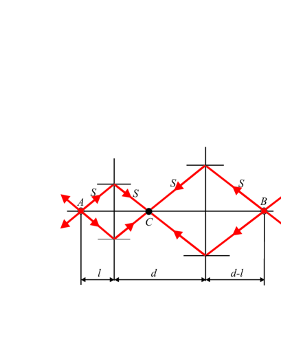
The principle of operation of a perfect lens is illustrated by a scheme of Fig.1, which had been first represented in Veselago’s work Veselago . In accordance with the Fresnel laws for the interface of media with refractive index (usual material) and with refractive index (”left-handed” metamaterial), the rays propagating from an object (point A) intersect at point B thus forming an image. This is an elementary picture, at first sight, but it becomes non- elementary if we consider spatial structure of electromagnetic fields at points B and C, and a direction of energy propagation in such systems. Here a question arises about singular points of electromagnetic field in homogeneous space, into which the energy flows in, from one direction, and flows out, from the other.
Consideration based on the field expansion over plane and evanescent waves Pendry proves to be deeper than a ray approach. It shows that near field amplification occurs in a metamaterial layer with due to the surface plasmon resonance, which is connected with a subsequent perfect focusing. Such kind of argumentation was put in doubt in Garcia ; Hooft . The case of almost-perfect lens, that is the case of slab with refractive index was considered in Merlin , but no focal spot at point B was detected. Thus, until the present work, no convincing solution of that problem had been obtained in a spatial domain, as far as I know.
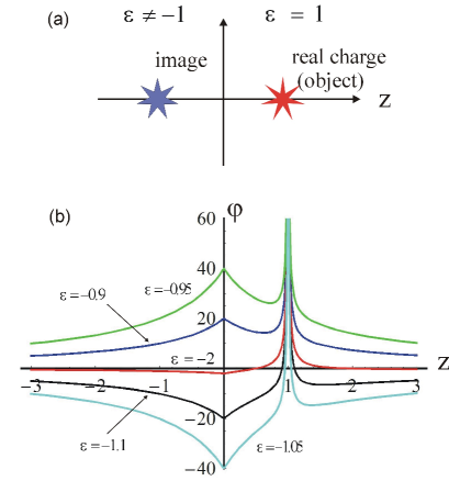
To make that problem clear, we first consider the case of near fields, i.e., the quasi-static Pendry perfect lens Pendry . Let us analyze a point charge in vacuum near a half- space with dielectric permittivity (Fig.2). Solution of such an electrostatic problem is well known Landau
| (1) | |||||
| (2) |
where are radius-vectors of real charge and its image respectively.
From that solution it is immediately seen that as the permittivity tends to -1, the solution tends to infinity near a surface, and thus it does not exist within the limit of (Fig.2b). From the physical viewpoint, the solution tendency to the infinity in whole space is due to the excitation of resonant surface plasmon waves at the interface. Meanwhile, the question arises: is there any meaningful solution at ? From the formal mathematical point of view, there is no bounded solution in whole space (except the charge position point). But if we admit the presence of only one or several singular points in the region of metamaterial then the solution becomes possible and obtains the form:
| (3) |
where the charges and their “positions” are arbitrary.
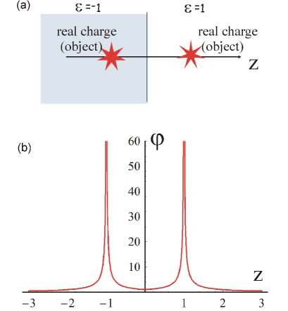
Thus, if there exist two equal and symmetrically situated charges, then the Laplace equation with standard boundary conditions at the interface has quite meaningful (but not the unique ones) solutions. Figure 3a,b illustrates such solutions for two equal real charges located symmetrically relative to interface. It is very important that the fields are bounded at the interface, and the surface plasmons are not excited.
For a finite-thickness layer with , the solution has the analogous form:
| (4) | |||||
where the choice of a homogeneous solution is not arbitrary, and the radius-vectors correspond to the A, B, and C points in Fig.1.
From (3) and (4) it is seen that solutions of the Maxwell equations corresponding to the source A in the region and having singularities at the ray intersection points B and/or C (Fig.1), and which correspond to real charges, exist both in the case of a half-space with and in the case of slab with . However, unlike a seeming asymmetry between object and its image of Fig.1, all charges of the system are now symmetric, have the same sign, and each of them cannot be considered as images of the others.
Thus, by an example of a quasi-static Pendry case Pendry it is already seen that optical system shown in Fig.1 cannot be considered as the lens, and it must necessarily include three real sources of a charge.
It is difficult to define energy flow in the quasi-static case, and therefore, the above reasoning is only the indirect evidence that the usual picture is not correct, and one cannot use the system of Fig.1 in the regime of a usual lens. For final evidence of that fact, we consider full electrodynamics problem with one or several interfaces between the right-handed medium with and the left-handed medium with . One can verify that there is no solution of the Maxwell equations with one source in the right-hand medium and without any sources in the ”left-handed” half-space. However, one may derive explicit solution of the Maxwell equations by admitting the existence of a finite number of singular points, where charges and currents arise.
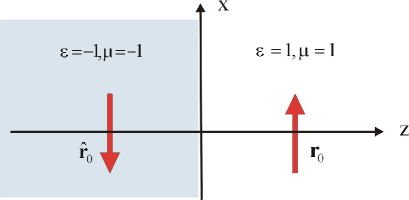
Consider a case of a single interface between right-and ”left-handed” matter. If the right- handed half-space contains a dipole with boundary-parallel orientation, then in the left-hand matter the dipole must be placed, which is directed in the opposite direction at the mirror- symmetrical point (see Fig.4). Formally speaking, the Hertz vector in the ”right-handed” medium has the form:
| (5) |
and in the ”left-handed” medium,
| (6) |
Using relations between Hertz potential and fields Vainstein
| (7) |
from (5) and (6) we find the electric and magnetic field fields, which satisfy standard continuity conditions for tangential components, that should be solution of Maxwell equation. Note that both (5) and (6) describe phase propagation from the source, and energy flow from the source (”right-handed” medium) and to the source (”left-handed” medium).
For the ”left-handed” slab, the solution is built analogously, and has the form
| in the source region | |||||
| inside slab | |||||
| (8) | |||||
| in the ”image” region |
where , and are radius-vectors of ray intersection points in Fig.1. It is very interesting that the solution (8) remains valid even in the case , but in this case positions of and are inside and outside slab, respectively. Of course in that case there are no singularities except for the dipole source at point and one cannot speak about lens effect.
The picture for the normally oriented dipole is fully analogous. In that case, however, one should choose a antisymmetrical combination of Hertz potentials.
To illustrate physical meaning of our solution and singular points , we plot Umov-Poynting vector distribution in the y-z plane (normal plane to the dipole orientation) for the case of parallel-boundary dipole (Fig.5). For more detailed demonstration see Klimov4 .
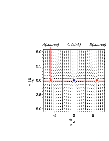
From Fig.5 (and Klimov4 ) it is seen that energy outgoes from two sources (A and B) , outside the “left handed ”slab, and moves towards the point C (inside slab), where it is absorbed by the third source to be named sink. Obviously, there is also a solution where the energy propagates from source C in the ”left-handed” slab to the sinks (A and B) in usual matter. Thus, the energy flow in the system shown in Fig.1 is not correct. Instead of it, one should use Fig.6, whose picture is radically different from that which prevails nowadays in the metamaterials community.
Above we have presented the solution in the absence of losses. We have also found the solution of Maxwell equation with three sources (8) for the case with losses as well, and this solution is continuously transformed into the solution (8) when losses tend to zero. In the case of the solution we have proposed, the symmetry of the source disposition does not let the surface plasmon waves to be excited, and the solution, therefore, remains finite as the losses tend to zero except for and points.
On the other hand, there also exists a solution of Maxwell equations with only one dipole source near the ”left-handed” layer with losses, but when it tends to infinity as losses are diminishing, because in such a system there occurs resonant excitation of surface plasmon waves. It is interesting to note that for this solution tends to the solution (8) in the case of small losses! In any case, the solution of Maxwell equations with only one source near the ”left-handed” layer with losses has maximum at the interface only and cannot be considered as conventional lens with well defined focal spot.
Despite the found solution does not allow us to consider the ”left-handed” slab as the perfect lens, we believe that it opens up new possibilities of using the layer with negative refractive index, . For example, by placing two excited atoms at points A and B and a non- excited one, at point , one may excite an atom in point with a probability close to unit (the probability that this atom remains unexcited is equal to the probability that both photons had flown in the direction opposite to the layer, that is, 1/4). An inverse initial conditions, with one excited atom (at C point) and two unexcited atoms are also possible. The second situation may turn out to be even more interesting because in this case there may be formed entangled state of the excited atoms (at A and B points). Perhaps, new logical elements for quantum computers can be elaborated on this direction.
Thus, we have strictly shown that a slab with negative refractive index could not be considered as a focusing element. We have also proposed to use more complex configurations of the sources and sinks in order to reveal new very interesting features of the layer with negative refractive index.
The author would like to express his gratitude to the Russian Foundation for Basic Research (grants # 05-02-19647 and #07-02-01328) and the Presidium of the Russian Academy of Sciences for financial support of the present work. The author is also grateful to N.I. Zheludev for hospitality and useful discussions of this work.
References
- (1) V. G. Veselago, The electrodynamics of substances with simultaneously negative values of and , Sov. Phys. Usp., 10 (1968) 509 .
- (2) J. B. Pendry, Negative refractive Makes a Perfect Lens, Phys. Rev. Lett., 85(2000) 3966.
- (3) N. Fang, H. Lee, C. Sun, X. Zhang, Sub–Diffraction-Limited Optical Imaging with a Silver Superlens , Science, 308 (2005)534
- (4) Z. Liu, H. Lee, Y. Xiong, C. Sun and X. Zhang, Far-field optical hyperlens magnifying sub-diffraction-limited objects, Science, 315 (2007) 1686.
- (5) I.I. Smolyaninov, Y.-J. Hung, and C.C. Davis, Magnifying superlens in the visible frequency range, Science, 315 (2007) 1699.
- (6) S. Kawata, A. Ono and P. Verma, Subwavelength colour imaging with a metallic nanolens, Nature Photonics, 2 (2008) 438.
- (7) N. Garcia, M. Nieto–Vesperinas, Left-Handed Materials Do Not Make a Perfect Lens Phys. Rev. Lett., 88(2002) 207403
- (8) G.W. t Hooft, Comment on ”negative refractive make a perfect lens, Phys.Rev.Lett.,87(2001)249701
- (9) R.Merlin, Analytical solution of the almost-perfect-lens problem, Appl. Phys. Lett., 84 (2004)1290
- (10) E. M. Lifshitz, L. D Landau, L. P. Pitaevskii, Electrodynamics of Continuous Media, 2nd ed.; Butterworth-Heinemann: Burlington, MA, 1984.
- (11) L.A.Vainstein, Electromagnetic waves, Moscow Radio i Svyaz (in Russian),1988.
- (12) http://demonstrations.wolfram.com/EnergyFlowInANegativeIndexMaterial/