4011 11institutetext: Forschungszentrum Dresden-Rossendorf, P.O. Box 510119, D-01314 Dresden, Germany 22institutetext: Institute of Fundamental Technological Research, 21, Świȩtokrzyska , 00-049 Warsaw, Poland 33institutetext: Astrophysikalisches Institut Potsdam, An der Sternwarte 16, D-14482 Potsdam, Germany 44institutetext: Department of Applied Mathematics, University of Leeds, Leeds, LS2 9JT, UK
Liquid metal experiments on the
helical magnetorotational instability
Abstract
The magnetorotational instability (MRI) plays an essential role in the formation of stars and black holes. By destabilizing hydrodynamically stable Keplerian flows, the MRI triggers turbulence and enables outward transport of angular momentum in accretion discs. We present the results of a liquid metal Taylor-Couette experiment under the influence of helical magnetic fields that show typical features of MRI at Reynolds numbers of the order 1000 and Hartmann numbers of the order 10. Particular focus is laid on an improved experiment in which split end caps are used to minimize the Ekman pumping.
Introduction.
Magnetic fields play a double role in the cosmos: First, planetary, stellar, and galactic fields are produced by the homogeneous dynamo effect in moving electrically conducting fluids. Second, magnetic fields can accelerate tremendously the formation of stars and black holes by enabling outward directed transport of angular momentum in accretion disks by virtue of the so-called magnetorotational instability (MRI). This instability was discovered as early as 1959, when Velikhov showed that a Taylor-Couette flow in its hydrodynamically stable regime (i.e. with outward increasing angular momentum) can be destabilized by an applied axial magnetic field [1]. It was only in 1991, however, that the importance of MRI for accretion disks in the vicinity of young stars and black holes was realized in a seminal paper by Balbus and Hawley [2].
The last decades have seen tremendous theoretical and computational progress in understanding the dynamo effect and the MRI. The hydromagnetic dynamo effect has even been verified experimentally in large-scale liquid sodium facilities in Riga, Karlsruhe, and Cadarache, and is presently studied in laboratories around the world [3, 4]. In contrast, attempts to study the MRI in the laboratory have been less successful so far. Recently, an MRI-like instability has been observed on the background of a turbulent spherical Couette flow [5], but the genuine idea that MRI would destabilize a hydrodynamically stable flow was not realized in this experiment.
One of the basic problems for the experimental investigation of the ”standard MRI”, with only an axial magnetic field being externally applied, is the need for flows with large magnetic Reynolds numbers . The crucial point is that the azimuthal field, which is essential for the MRI mechanism to work, must be produced from the applied axial field by induction effects proportional to . The natural question, why not substitute the induction process by externally applying the azimuthal field as well, was addressed by Hollerbach and Rüdiger [6]. Exemplified in a Taylor-Couette configuration, it was shown that the scaling properties for this ”helical MRI”, as we call it now, are completely different from those of the ”standard MRI”. While the latter is governed by the magnetic Reynolds number and the Lundquist number , the former depends only on the hydrodynamic Reynolds number and on the Hartmann number . For liquid metals, with their small magnetic Prandtl number , this makes a dramatic difference for the feasibility of MRI experiments, since and .

We have to point out, though, that there is no real breach between “standard MRI” and “helical MRI”. This can be clearly seen in Fig. 1 of [6], where the critical is plotted against the rotation ratio of outer to inner cylinder of a Taylor-Couette set-up. The extremely steep increase of this curve at the Rayleigh line, which occurs for a purely axial magnetic field, is just smeared out when an azimuthal field is added.
In this paper, we summarize the main results of a first experimental verification of this idea obtained in the framework of the PROMISE experiment (Potsdam ROssendorf Magnetic InStability Experiment) which were already published in [7, 8, 9, 10], and we report some new results of an improved version of this experiment.
1 The experimental facility.
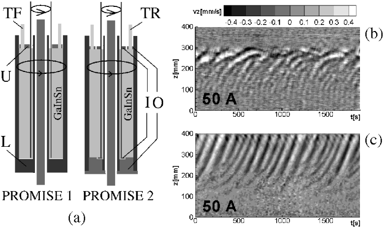
The basic part of PROMISE is a cylindrical containment vessel V made of copper (see Fig. 1). The inner wall of the vessel V is 10 mm thick, and extends in radius from 22 to 32 mm; the outer wall is 15 mm thick, extending from 80 to 95 mm. This vessel is filled with the eutectic alloy Ga67In20.5Sn12.5 which is liquid at room temperatures. The vessel V, which is completely made of copper in the first version of the experiment (henceforth called PROMISE 1), is fixed, via an aluminum spacer D, on a precision turntable T; the outer copper cylinder of the vessel represents the outer cylinder of the Taylor-Couette cell. The inner copper cylinder I of the Taylor-Couette flow is fixed to an upper turntable, and is immersed into the liquid metal from above. It has a thickness of 4 mm, extending in radius from 36 to 40 mm, thus leaving a gap of 4 mm between this immersed cylinder I and the inner wall of the containment vessel V. The actual Taylor-Couette cell extends in radial direction over a cylindrical gap of width mm, and in axial direction over the liquid metal height mm, resulting in an aspect ratio of 10.
In the PROMISE 1 configuration, the upper endplate is a non-rotating Plexiglass lid P fixed to the frame F. The bottom, however, is simply part of the copper vessel V, and rotates with the outer cylinder. With respect to both their rotation rates and electrical conductivities, there is thus a clear asymmetry in the end caps.
Figure 2a shows the changes made for PROMISE 2 to improve this situation: First, both end caps are made of insulating material in order to avoid short-circuiting of currents along the copper end cap at the bottom (those currents had been shown to be dangerous by possibly changing the rotation profile via azimuthal forces [11, 12]). Second, both the upper and the lower end caps are split into two rings, the inner rotating with the inner cylinder and the outer rotating with the outer cylinder. In [13] it had been shown that this splitting yields a minimization of the Ekman pumping if the position of the splitting is at 0.4 of the gap width . Third, the co-rotation of the two rings with one of the cylinders made it necessary to change the signal path of the ultrasonic transducers.
These two transducers provide full profiles of the axial velocity along the beam-lines parallel to the axis of rotation. While in PROMISE 1 they are inserted in the upper Plexiglass end cap that is fixed to the laboratory frame, in PROMISE 2 they must be connected via a sliding contact to the signal processing computer (DOP 2000).
The configuration of magnetic fields is the same for PROMISE 1 and PROMISE 2. An axial magnetic field in the order of 10 mT is produced by a double-layer coil with 76 windings (C in Fig. 1). The omission of windings at two symmetric positions close to mid-height, as seen in Fig. 1a, was motivated by a coil optimization to maximize the homogeneity of the axial field throughout the fluid volume. The coil is fed by currents up to 200 A, beyond which a significant heating of the coil sets in. The azimuthal field, also in the order of 10 mT, is generated by a current through a water-cooled copper rod R of radius 15 mm. The special power supply (PS in Fig. 1c) for this axial current is capable of delivering up to 8000 A.
2 Some results
We have carried out a large number of experimental runs in order to cover a wide range of parameter dependencies. Typically, the duration of an experimental run was 1900 sec, after a waiting time of one hour and more. Many details for the PROMISE 1 set-up can be found in the publications [7, 8, 9, 10].

One of the most significant features of the MRI is that, for fixed and fixed azimuthal field , it shows up only in a finite interval of the Hartmann number ( is the conductivity of the liquid, its density, and its kinematic viscosity). This appearance and disappearance of a travelling mode is a suitable indicator for the existence of the proper MRI mode and its distinction from other possible flow structures.
In Fig. 2b,c we represent the results for rotation rates of Hz (i.e. ) and (i.e. ) which is slightly above the Rayleigh value . The current in the coil was fixed to A (i.e. Ha=7.9). In the PROMISE 1 case (Fig. 2b), the axial current was set to A (i.e. ), in the PROMISE 2 (Fig. 2c) case to A (i.e. ), a difference that is, however, not essential. The grey scale of the plots indicates the axial velocity component measured along the ultrasound beam, from which we have subtracted the (z-dependent) time average in order to filter out the two Ekman vortices which appear already without any magnetic field. These Ekman vortices, which in the PROMISE 1 version are characterized by inward radial flows close to the upper and lower end-plates and a jet-like radial outflow in the centre of the cylinder [14], are significantly suppressed in the PROMISE 2 version due to the use of split end caps. In PROMISE 1, the wave dies away at the position of the radial jet (which is not always at mid-height). In contrast to this, in PROMISE 2 the wave propagates throughout the total height of the cell.
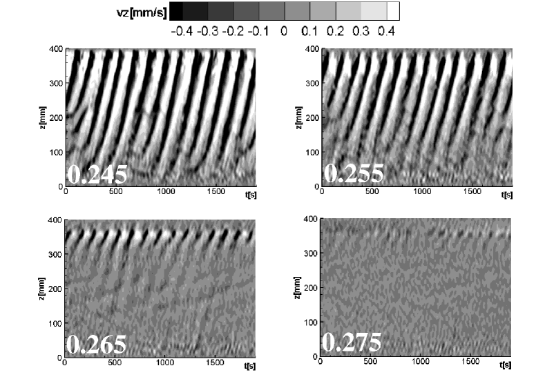
This much improved behaviour of the MRI in PROMISE 2 can be visualized nicely when crossing the Rayleigh line. It is known [9] that the travelling wave appears already with a stationary outer cylinder, i.e. at , although with a very low frequency. With increasing , the wave frequency increases and typically reaches a value of at the Rayleigh value . Figure 3 shows now in detail what happens with the travelling MRI wave when crosses the Rayleigh line. The parameters for this run were Hz (i.e. ), A (i.e. ), A. It is clearly visible that the MRI wave is still present at , becomes significantly weaker at , and has completely died at .
This transition is further analyzed in Fig. 4 which shows the rms of the axial velocity perturbation in dependence on , now both for A and A (which corresponds to and 4.5, respectively).
The measured values (full lines) are compared with the numerical results of a 2D solver (dashed lines), but also with the results of a 1D solver for the onset of the absolute and the convective instability [15, 16] (courtesy of Jānis Priede). It is most remarkable that the 1D results for the onset of the absolute instability correspond nearly perfectly with the results of the 2D solver, while the thresholds for the convective instability are situated at much higher values of . Compared to the 2D numerical curves, the experimental curves are shifted only slightly towards higher . As expected, we see also that for increasing the threshold of the instability shifts to higher values of .
3 Conclusions
We have obtained experimental evidence for the existence of the MRI in current-free helical magnetic fields. The symmetrization of the axial boundary conditions and the use of split end caps in PROMISE 2 has led to a strong reduction of the Ekman pumping and hence to an avoidance of artefacts in the radial jet flow region. The MRI wave extends clearly beyond the Rayleigh line, and its behaviour is in good correspondence with both 2D simulations and 1D simulations for the absolute instability, but in stark contrast with 1D simulations for the convective instability. This indicates that the observed MRI wave is indeed a global instability and not only a noise triggered convective instability as claimed recently [17]. Further dependencies of the MRI on parameters like , , and , as well as their comparison with numerical predictions will be published elsewhere.
We are grateful to Jānis Priede for many fruitful discussions on MRI, and for sharing with us his results for the convective and absolute instability. This work was supported by the German Leibniz Gemeinschaft, within its ”Senatsausschuss Wettbewerb” (SAW) programme.
References
- [1] E.P. Velikhov. Stability of an ideally conducting liquid fluid between cylinders rotating in a magnetic field. Sov. Phys. JETP, vol. 9 (1959), pp. 995–998.
- [2] S.A. Balbus and J.F. Hawley. A powerful local shear instability in weakly magnetized disks. 1. Linear analysis. Astrophys. J., vol. 376 (1991), pp. 214–222.
- [3] A. Gailitis, O. Lielausis, E. Platacis, G. Gerbeth, and F. Stefani. Colloquium: Laboratory experiments on hydromagnetic dynamos. Rev. Mod. Phys., vol. 74 (2002), pp. 973–990.
- [4] F. Stefani, A. Gailitis, and G. Gerbeth. Magnetohydrodynamic experiments on cosmic magnetic fields. ZAMM, 88 (2008), 930–954.
- [5] D. Sisan et al.. Experimental observation and characterization of the magnetorotational instability. Phys. Rev. Lett., vol. 93 (2004), Art. No. 114502.
- [6] R. Hollerbach and G. Rüdiger. New type of magnetorotational instability in cylindrical Taylor-Couette flow. Phys. Rev. Lett., vol. 95 (2005), Art. No. 124501.
- [7] F. Stefani et al.. Experimental evidence for magnetorotational instability in a Taylor-Couette flow under the influence of a helical magnetic field. Phys. Rev. Lett., vol. 97 (2006), Art. No. 184502 .
- [8] G. Rüdiger et al.. The travelling-wave MRI in cylindrical Taylor-Couette flow: Comparing wavelengths and speeds in theory and experiment. Astrophys. J., vol. 649 (2006), pp. L145-L147.
- [9] F. Stefani et al.. Experiments on the magnetorotational instability in helical magnetic fields. New J. Phys., vol. 9 (2007), Art. No. 295.
- [10] F. Stefani et al.. Results of a modified PROMISE experiment. Astron. Nachr., vol. 329 (2008), pp. 652-658.
- [11] J. Szklarski. Ekman-Hartmann layer in a magnetohydrodynamic Taylor-Couette flow. Phys. Rev. E, vol. 76 (2007), Art. No. 066308.
- [12] J. Szklarski and G. Gerbeth. Boundary layer in the MRI experiment PROMISE. Astron. Nachr., vol. 329 (2008), pp. 667-674.
- [13] J. Szklarski. Reduction of boundary effects in spiral MRI experiment PROMISE. Astron. Nachr., vol. 328 (2007), pp. 499–506.
- [14] A. Kageyama, H. Ji, J. Goodman, F. Chen, E. Shoshan. Numerical and experimental investigation of circulation in short cylinders. J. Phys. Soc. Jpn., vol. 73 (2004), pp. 2424-2437. Astron. Nachr., vol. 329 (2008), pp. 659-666.
- [15] J. Priede, I. Grants, and G. Gerbeth. Inductionless magnetorotational instability in a Taylor-Couette flow with a helical magnetic field. Phys. Rev. E, vol. 75 (2007), Art. No. 047303.
- [16] J. Priede and G. Gerbeth. Absolute versus convective helical magnetorotational instability in a Taylor-Couette flow. Phys. Rev. E, submitted (2008); arxiv:0810.0386
- [17] W. Liu. Noise-sustained convective instability in a magnetized Taylor-Couette flow. Astrophys. J, submitted (2008); arxiv:0808.2513